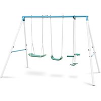
Olav - Children's swing Klarfit - Free user manual and instructions
Find the device manual for free Olav Klarfit in PDF.


| Product type | Children's swing |
| Brand | Klarfit |
| Model | Olav |
| Reference | 10026906, 10026907 |
| Number of seats | 2 |
| Recommended age | 3 to 8 years |
| Maximum total user weight | 45 kg |
| Use | Outdoor |
| Frame material | Steel |
| Seat material | Plastic |
| Suspension type | Sheathed chain |
| Seat height from ground | ≥ 350 mm |
| Ground anchoring | Optional (spiral anchor or concrete) |
| Minimum safety distance | 2 meters from obstacles |
| Assembly | By an adult only |
| Recommended maintenance | Periodic lubrication, check of screws and wear |
| Manufacturer | Chal-Tec GmbH, Germany |
| Package contents | Frame, 2 seats, 2 footrests, screws, tools |
Frequently Asked Questions - Olav Klarfit
User questions about Olav Klarfit
0 question about this device. Answer the ones you know or ask your own.
Ask a new question about this device
Download the instructions for your Children's swing in PDF format for free! Find your manual Olav - Klarfit and take your electronic device back in hand. On this page are published all the documents necessary for the use of your device. Olav by Klarfit.
USER MANUAL Olav Klarfit
INHALTSVERZEICHNIS
line
| Position | Length (m) | | -------- | ---------- | | N5 | 0 | | N9 | 0 | | L1 | 0 | | M1 | 0 | | M5 | 0 | | N5 | 0 |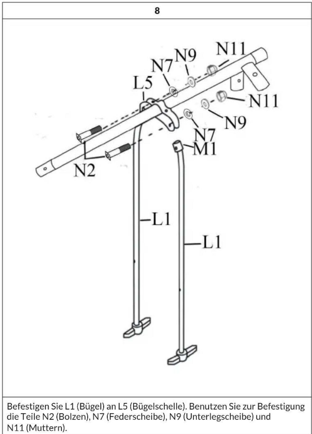
Berlin Brands Group UK Limited
PO Box 42
272 Kensington High Street
London, W8 6ND
United Kingdom
Dear Customer,
Congratulations on purchasing this device. Please read the following instructions carefully and follow them to prevent possible damages. We assume no liability for damage caused by disregard of the instructions and improper use. Scan the QR code to get access to the latest user manual and more product information.

CONTENTS
Safety Instructions 24
Required Tools 26
Scope of Delivery 26
Mounting 29
Anchoring 39
Manufacturer & Importer (UK) 41
TECHNICAL DATA
| Item number 10026906, 10026907 | |
| Maximum permissible body weight Up to 45 kg | |
SAFETY INSTRUCTIONS
Hints on age and weight
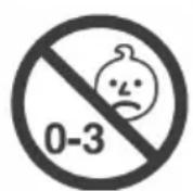
The swing is suitable for children aged 3-8 years. The swing is not suitable for children under 3 years of age, as they could be injured by small parts or the long ropes. The swing is not suitable for adults or children weighing more than 45 kg.
General Hints
- Only one child per seat at any one time.
- For outdoor use.
- Check all nuts, bolts and fittings for tightness and tighten if required.
- Check all coverings for bolts and sharp edges and replace when required
- Oil all metallic moving parts.
- Check swing seats, ropes and other means of attachments for evidence of deterioration. Replace when required in accordance with the manufacturer's instructions.
- Please take note: As an extra precaution, check this toy regularly for signs of wear and damage.
Hints on Placement
- Place the product on a level surface at least 2 metres from any obstructions such as a fence, garage, house, wall, overhanging branches, laundry line or electrical wires.
- For safety reasons, this swing must be anchored into the ground.
- Anchors shall be places level with or under the ground in order to reduce tripping hazards.
- Ensure the child is not facing the sun when on the swing.
- Leave all fittings fingeright until assembly is complete, for ease of construction. Then tighten Firmly.
- Do not install the product on concrete, asphalt or hard surfaces.
Hints on Use
- Do not allow children to stand on the swing or glider seats.
- Do not allow children to get off the swings or glider while they are still moving.
- Do not twist swing ropes or wrap them over the top bar.
- Do not allow loose, hooded or baggy clothes to be worn since children can get trapped and may be unable to free themselves.
- Do not allow children to climb on this equipment.
- Do not allow children to wander into the play area when the equipment is in use.
- Gliders and swings must not exceed an angle of 60 degrees from the ground.
Hints on mounting and maintenance
- Failure to assemble and maintain this item as per these instructions may cause injury to the user.
- Packaging materials are not toys. Please remove all packaging and packing tags / wires before giving this toy to your child.
• Adult assembly required. - For use under adult supervision.
- Maintenance to be carried out under the direct supervision of a responsible adult.
- For family domestic use only.
- Once assembly is complete, carefully check the equipment before use. If you find any problems, do not allow children to use the equipment until it is fit for use.
REQUIRED TOOLS
 | 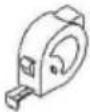 | 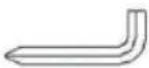 | 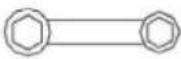 |
| Hammer Measuring tape Allen wrench(included) | Wrench(included) | ||
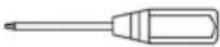 Screwdriver Screwdriver | |||
Screwdriver
SCOPE OF DELIVERY
he parts displayed below are for the main frame assembly:
| A1 | 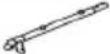 | Top tube left | 1 PCS |
| A2 |  | Long top tube | 1 PCS |
| A3 |  | Upper leg section | 4 PCS |
| A5 |  | Lower leg section | 4 PCS |
| A6 |  | Cross brace | 2 PCS |
The hardware displayed below is for the main frame assembly:
| B1 |  | Screw 5/16" * 63 mm | 14 PCS |
| B2 |  | Screw 5/16" * 63 mm | 4 PCS |
| B3 |  | Nut 5/16" | 18 PCS |
| B4 |  | Plastic cap | 18 PCS |
| B5 | [bowel] | Washer | 32 PCS |
| B6 | [bowel] | Washer | 4 PCS |
The parts displayed below are for the glide ride assembly:
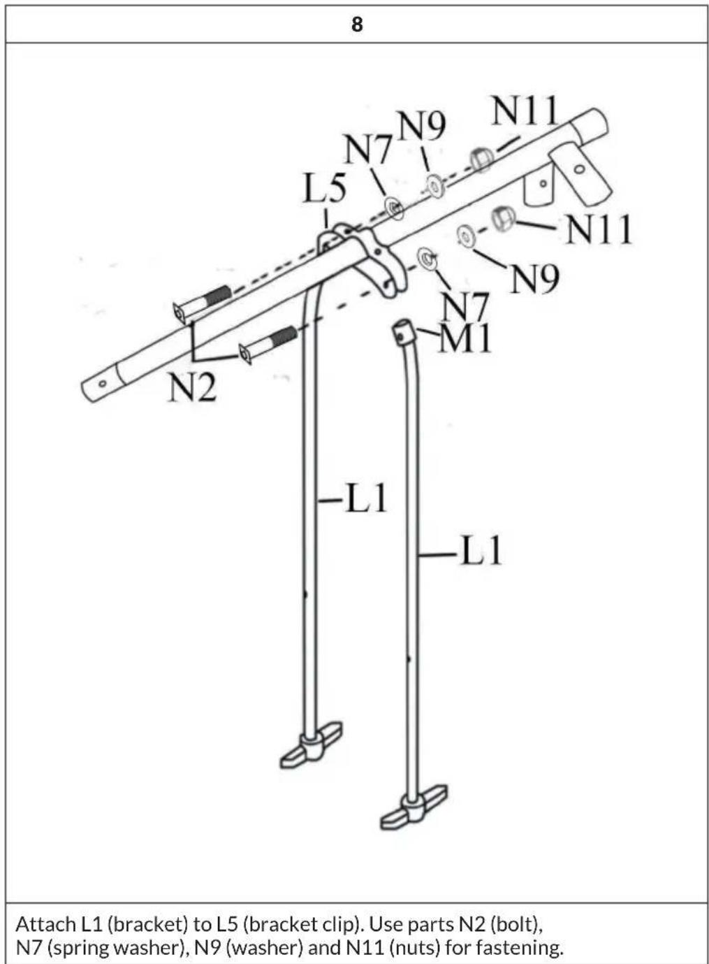
| L1 | 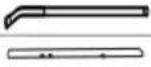 | Bracket | 2PCS |
| L2 | Seat suspension | 2 PCS | |
| M1 |  | Cap (mounted) | 2 PCS |
| M2 |  | Small bearing (mounted) | 2 PCS |
| M3 |  | Large bearing (mounted) | 4 PCS |
| M4 |  | Seat | 2 PCS |
| M5 |  | Footrest | 2 PCS |
The brackets displayed below are used for the glide ride assembly:
| L4 | 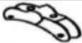 | Terminal | 1 PCS |
| L5 |  | U-bolt clamp | 1 PCS |
| L6 |  | Washer | 4 PCS |
| N3 |  | Screw 5/16" * 25 mm | 2 PCS |
| N8 |  | Nut 5/16" | 2 PCS |
| N14 |  | Plastic cap | 2 PCS |
The hardware displayed below is used for the glide ride assembly:
| N1 |  | Bolt 1/4" * 35 mm | 4 PCS |
| N2 |  | Bolt 1/4" * 45 mm | 2 PCS |
| N5 |  | Screw V6 ∅ 5*15 | 4 PCS |
| N6 |  | Hook bolt | 2 PCS |
| N7 | [OZTA] | Spring washer | 4 PCS |
| N9 |  | Washer | 12 PCS |
| N11 | [A530] | Nut 1/4" | 4 PCS |
| N12 |  | Mother | 4 PCS |
The parts displayed below are used for the swing seat assembly:
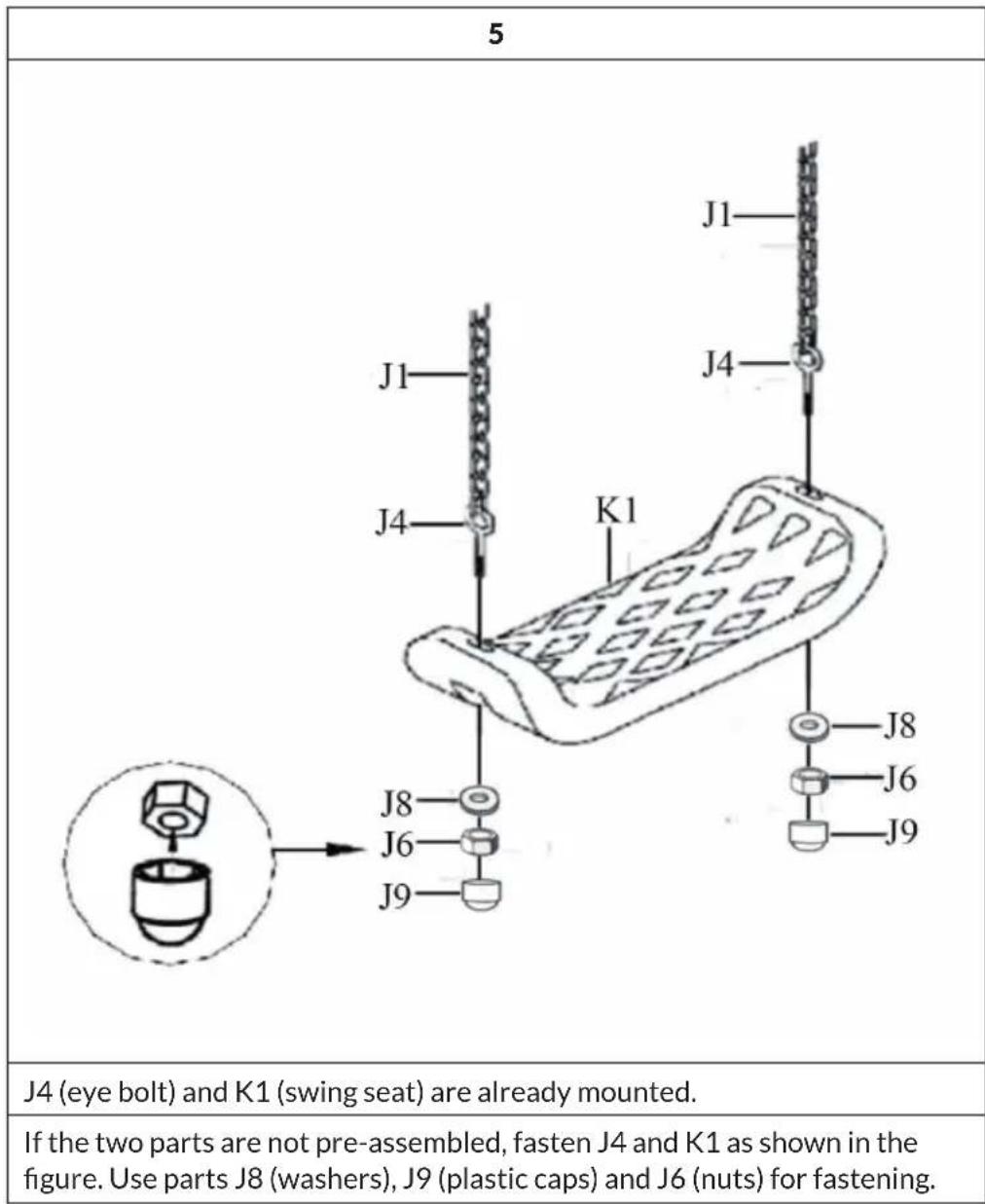
| J1 | Sheathed chain | 4 PCS | |
| J3 | Eyebolt & Accessories | 4 PCS | |
| J4 | Eye bolt (mounted) | 4 PCS | |
| K1 | Swing seat | 2 PCS |
The hardware displayed below is used for the swing seats:
| J6 |  | Nut 5/16" | 8 PCS |
| J8 |  | Washer | 8 PCS |
| J9 |  | Plastic cap | 8 PCS |
MOUNTING
Assembly Instructions
- Please the playground equipment on level ground, not less than 6ft (1.8m) from any structure or obstruction such as a fence, garage, house, overhanging branches, laundry lines or electrical wires.
- Do not install the playground equipment over concrete, asphalt, packed earthe or any other hard surface. A fall onto a hard surface can result in serious injury to the user.
- Do not over-tighten the nuts and bolts when you are assembling your playground equipment. This will allow for some possible adjustments and ease of installation.
- Once you have finished the assembly of the playground equipment go back over all of the nuts and bolts and properly tighten all of them before using the playground equipment
Mounting Instructions
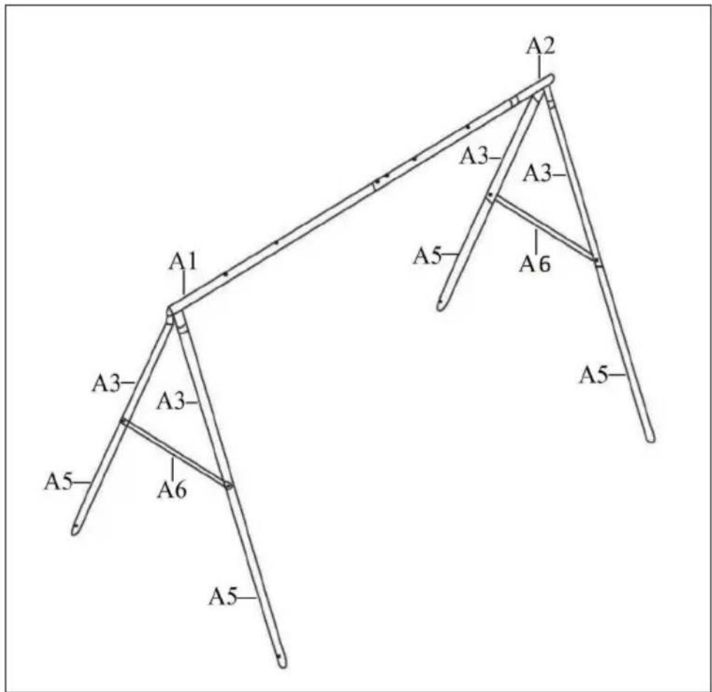
A1: Top tube left
A2: Long top tube
A3: Upper leg section
A5: Lower leg section
A6: Cross brace
| 1 |
| Slide A1 (left top tube) onto A2 (long top tube) and secure the tubes with parts B1 (bolts), B5 (washers), B3 (nuts) and B4 (plastic caps) |
| Note: Ensure that the concave hole is facing down. |
| 2 |
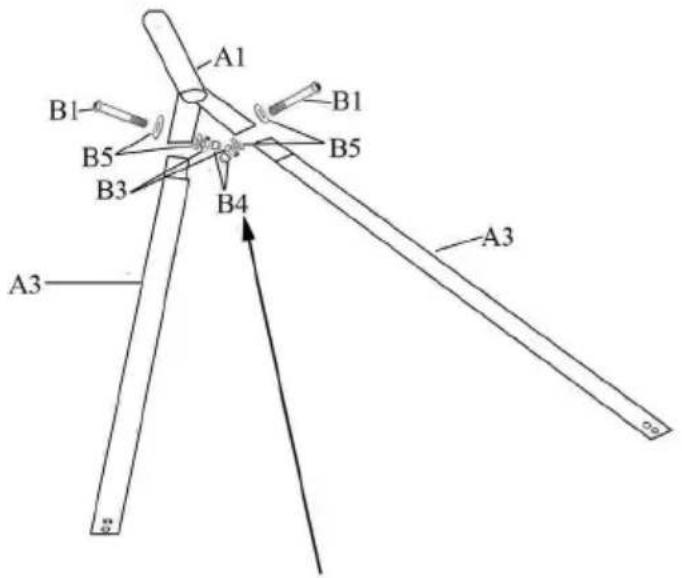 |
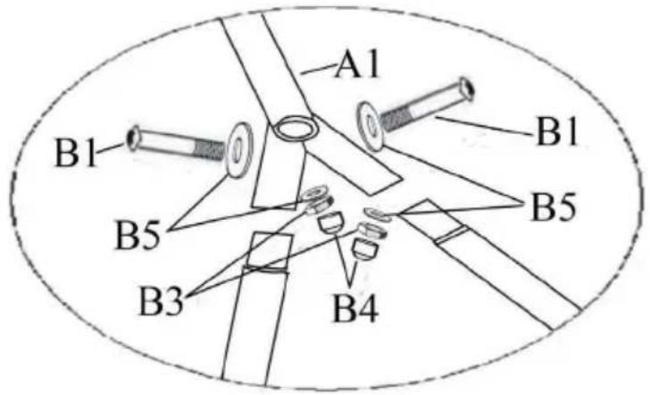 |
| Insert the short end of A3 (leg top) into the socket at the end of A1 (top tube left) and align the holes. |
| Use parts B1 (bolts), B5 (washers), B3 (nuts) and B4 (plastic caps) to secure. |
| Attach the other two leg tops in the same way to the base on the other side of A2 (long top tube). |
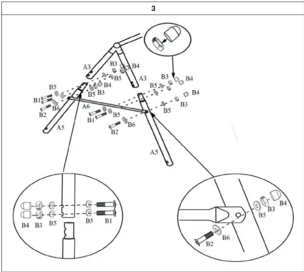
| Insert the end of A3 (leg top) into the socket of A5 (lower leg section) and align the holes with each other. |
| Use parts B1 (bolts) for fastening, B5 (washers), B3 (nuts) and B4 (plastic caps). |
| Slide A6 (cross brace) onto A5 (lower leg section) and secure the cross brace with parts B2 (bolts), B6 (spring washers), |
| B5 (washers), B3 (nuts) and B4 (plastic caps). |
| Repeat the steps to attach A3 (leg top), A5 (leg bottom) and A6 (cross brace) on the other side of A2 (long top tube). |
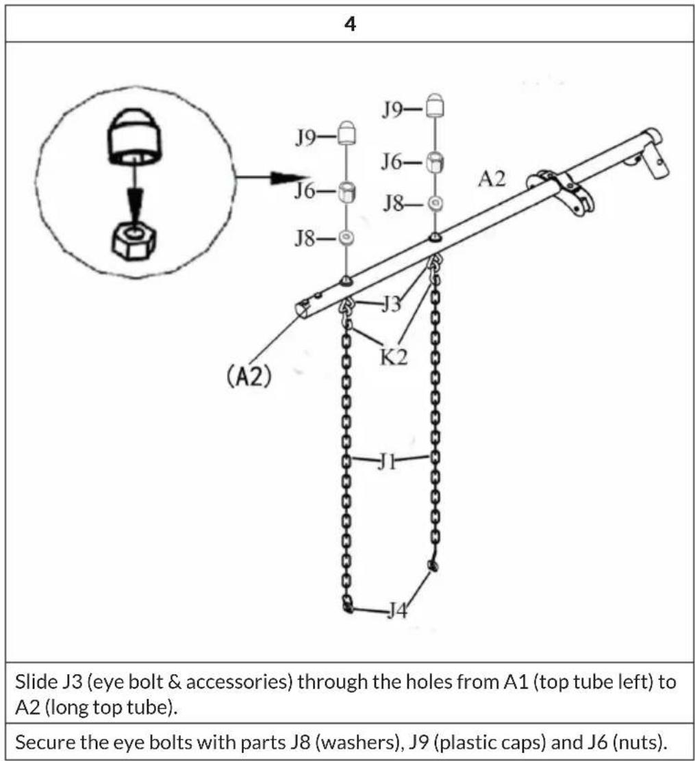
| 6 |
| N14 L6 N8 L5 L4 L6 N3 |
| Attach L5 (bracket clip), L4 (clamp) and L6 (washers) to A2 (long top tube) as shown in the illustration. |
| Then tighten N3 (bolts) and N8 (nuts) with a spanner and screwdriver. |
| 7 |
| M1 L1 N5 N9 M5 N9 N5 |
| Connect M5 (footrest) and L1 (bracket). Use parts N5 (screws) and N9 (washers) for fastening. |
| M1 (cap), M2 (small bearing) and L1 (bracket) are already mounted. If the parts are not pre-assembled, attach M1 on top of L1 and align the holes. Then push M2 through the holes of M1 and L1. |
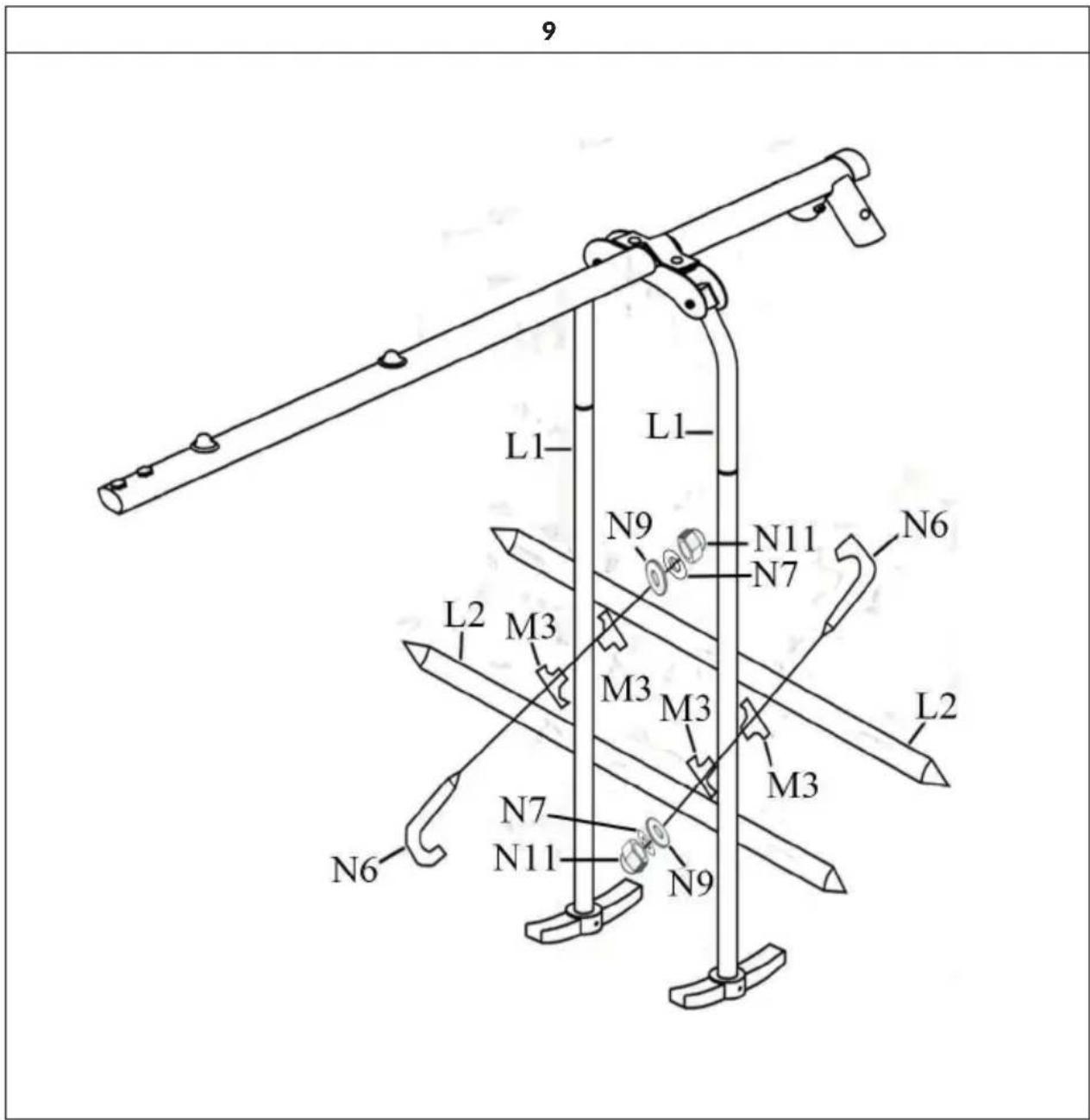
Insert 2x M3 (large bearing) into L1 (bracket). Then attach L2 (seat suspension) to L1 (bracket). Use parts N6 (hook bolt), N9 (washers), N7 (spring washers) and N11 (nuts) for fixing. But do not tighten the parts completely yet!
Fasten the other seat suspension to the bracket in the same way. Only then tighten all parts.
| 10 |
| Attach M4 (seat) with N1 (bolt) to N2 (seat suspension). |
| Secure the seat with parts N1 (bolts), N9 (washers) and N12 (nuts). |
ANCHORING
Optionally you can secure the swing with ground anchors (not included). The advantage of anchoring with ground anchors is that you can move the play equipment at any time or move it to another location. This type of anchoring is particularly suitable for hard ground.
- If your soil is soft (sand, etc.), the corkscrew method is recommended.
- If you wish to permanently secure your set, either type of anchor may set in concrete.
Note: Ensure equipment is firmly anchored (cementing is usually recommended). Before equipment is completed, do not bury the legs more than 76 mm below the ground surface. This will ensure sufficient space remains under the swinging plays. Be certain that all anchoring devices (including concrete) are placed below the level of the playing surface or below ground level to prevent tripping.
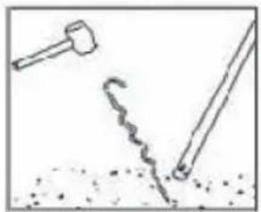
Corkscrew Anchors
- Be sure the swing set, is located on level ground.
- Turn the corkscrew anchor into the ground until only the hooked end is above the ground next to the leg.
- Insert the hooked end into the bottom opening of the leg. Ensure that the hooked end is secure in the let opening.
natural_image
Simple line drawing of a hammer striking a surface with a coiled tool (no text or symbols)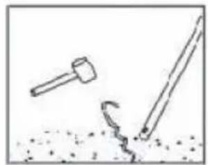
natural_image
Simple line drawing of a hammer and a nail on ground (no text or symbols)
natural_image
Simple line drawing of a hammer striking a surface with a stick (no text or symbols)Anchoring in Concrete
To increase safety, we recommend that you anchor the swing in concrete if possible. If you place the swing on a loose surface, always anchor the frame in concrete (not included). Follow the steps below to do this:
• Make sure that you place the swing on a level surface.
- Dig cylindrical holes in the ground where you want to anchor the legs. The holes should be about 60 mm deep and 32 mm wide. Use a shovel to widen the lower part of the hole so that the bottom diameter of the hole is larger than the top opening (see illustration). In the middle of the hole, prepare a 51 mm high gravel or stone bed for the legs of the swing (see illustration).
- Now place the rocking legs in the holes and fill the holes with about 20.5 kg of concrete.
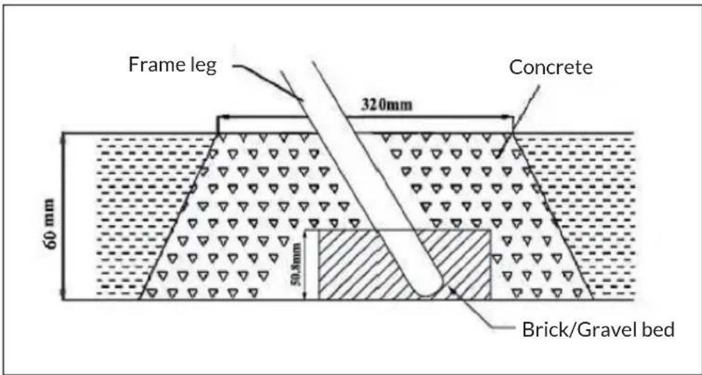
- Cover concrete with dirt and protective surface material.
- Allow about 6-7 days for concrete to dry properly.
- You must maintain a minimum of 350 mm ground clearance.
MANUFACTURER & IMPORTER (UK)
Manufacturer:
Chal-Tec GmbH, Wallstrasse 16, 10179 Berlin, Germany.
Importer for Great Britain:
Berlin Brands Group UK Limited
PO Box 42
272 Kensington High Street
London, W8 6ND
United Kingdom
Gentile cliente,
INDICE
PRODUTTORE E IMPORTATORE (UK)
Produttore:
Chal-Tec GmbH, Wallstraße 16, 10179 Berlino, Germania.
Berlin Brands Group UK Limited
PO Box 42
272 Kensington High Street
London, W8 6ND
United Kingdom
Estimado cliente,
ÍNDICE
Berlin Brands Group UK Limited
PO Box 42
272 Kensington High Street
London, W8 6ND
United Kingdom
Chère cliente, cher client,
Berlin Brands Group UK Limited
PO Box 42
272 Kensington High Street
London, W8 6ND
United Kingdom

bar
| Category | Value | |---|---| | Category 1 | 100 | | Category 2 | 100 | | Category 3 | 100 | | Category 4 | 100 | | Category 5 | 100 | | Category 6 | 100 | | Category 7 | 100 | | Category 8 | 100 | | Category 9 | 100 | | Category 10 | 100 | | Category 11 | 100 | | Category 12 | 100 | | Category 13 | 100 | | Category 14 | 100 | | Category 15 | 100 | | Category 16 | 100 | | Category 17 | 100 | | Category 18 | 100 | | Category 19 | 100 | | Category 20 | 100 | | Category 21 | 100 | | Category 22 | 100 | | Category 23 | 100 | | Category 24 | 100 | | Category 25 | 100 | | Category 26 | 100 | | Category 27 | 100 | | Category 28 | 100 | | Category 29 | 100 | | Category 30 | 100 | | Category 31 | 100 | | Category 32 | 100 | | Category 33 | 100 | | Category 34 | 100 | | Category 35 | 100 | | Category 36 | 100 | | Category 37 | 100 | | Category 38 | 100 | | Category 39 | 100 | | Category 40 | 100 | | Category 41 | 100 | | Category 42 | 100 | | Category 43 | 100 | | Category 44 | 100 | | Category 45 | 100 | | Category 46 | 100 | | Category 47 | 100 | | Category 48 | 100 | | Category 49 | 100 | | Category 50 | 100 | | Category 51 | 100 | | Category 52 | 100 | | Category 53 | 100 | | Category 54 | 100 | | Category 55 | 100 | | Category 56 | 100 | | Category 57 | 100 | | Category 58 | 100 | | Category 59 | 100 | | Category 60 | 100 | | Category 61 | 100 | | Category 62 | 100 | | Category 63 | 100 | | Category 64 | 100 | | Category 65 | 100 | | Category 66 | 100 | | Category 67 | 100 | | Category 68 | 100 | | Category 69 | 100 | | Category 70 | 100 | | Category 71 | 100 | | Category 72 | 100 | | Category 73 | 100 | | Category 74 | 100 | | Category 75 | 100 | | Category 76 | 100 | | Category 77 | 100 | | Category 78 | 100 | | Category 79 | 100 | | Category 80 | 100 | | Category 81 | 100 | | Category 82 | 100 | | Category 83 | 100 | | Category 84 | 100 | | Category 85 | 100 | | Category 86 | 100 | | Category 87 | 100 | | Category 88 | 100 | | Category 89 | 100 | | Category 90 | 100 | | Category 91 | 100 | | Category 92 | 100 | | Category 93 | 100 | | Category 94 | 100 | | Category 95 | 100 | | Category 96 | 100 | | Category 97 | 100 | | Category 98 | 100 | | Category 99 |


- INHALTSVERZEICHNIS
- Dear Customer,
- CONTENTS
- TECHNICAL DATA
- SAFETY INSTRUCTIONS
- Hints on age and weight
- General Hints
- Hints on Placement
- Hints on Use
- Hints on mounting and maintenance
- REQUIRED TOOLS
- SCOPE OF DELIVERY
- MOUNTING
- Assembly Instructions
- Mounting Instructions
- ANCHORING
- Corkscrew Anchors
- Anchoring in Concrete
- MANUFACTURER & IMPORTER (UK)
- Manufacturer:
- Importer for Great Britain:
- Gentile cliente,
- INDICE
- PRODUTTORE E IMPORTATORE (UK)
- Produttore:
- Estimado cliente,
- ÍNDICE
- Chère cliente, cher client,
Brand : Klarfit
Model : Olav
Category : Children's swing