DVTB202 0902 - Vacuum Cleaner Armor All - Free user manual and instructions
Find the device manual for free DVTB202 0902 Armor All in PDF.


User questions about DVTB202 0902 Armor All
0 question about this device. Answer the ones you know or ask your own.
Ask a new question about this device
Download the instructions for your Vacuum Cleaner in PDF format for free! Find your manual DVTB202 0902 - Armor All and take your electronic device back in hand. On this page are published all the documents necessary for the use of your device. DVTB202 0902 by Armor All.
USER MANUAL DVTB202 0902 Armor All
natural_image
Exterior view of a gray and black plastic container (no visible text or symbols)2.5 Gallon / 2.5 GALLONS / 2.5 Galones
- Model No.
Read and understand this manual before use. Keep this manual for future reference.
POUR GARANTIR VOTRE SÉCURITÉ
Important Safety Instructions.... 3
Symbols......8
Unpacking & Checking Carton Contents....9
General Assembly Instructions....10
General Operation....11
Dry Vacuum Operation....13
Liquid Vacuum Operation....14
Blower Operation.... 15
Inflator Nozzle Adapter Operation.... 16
Maintenance....17
Installing & Cleaning Cartridge Filter....18
Environmentally Safe Battery Disposal....19
Troubleshooting.... 20
Exploded View.... 21
Parts List.... 22
Thank you for purchasing this Armor All ^® wet/dry vacuum cleaner. Feel confident that with our Armor All ^® wet/dry vac you are obtaining a high-quality product engineered for optimal performance. This vacuum is capable of picking up liquids and dry materials.

IMPORTANT INFORMATION
GALLONS
"Tank Size" refers to the actual tank volume and does not reflect capacity available during operation.
PEAK HP
"Peak Horsepower" is a term used in the wet-dry vac industry for consumer comparison purposes. It does not denote the operational horsepower output of a wet-dry vac, but rather the horsepower output of a motor, including the motor's inertial contribution, achieved in laboratory testing. In actual use, motors do not operate at the peak horsepower shown.
FOR YOUR SAFETY: CAREFULLY READ AND UNDERSTAND ALL INSTRUCTIONS.
EN
WARRANTY
We take pride in producing a high-quality, durable product. This vacuum carries a limited two (2) year warranty against defects in workmanship and materials from date of purchase (or, for deliveries in the State of California, two years from the date of delivery), under normal household use. Please keep your receipt as proof of purchase. This warranty gives you specific legal rights, and you may have other rights, which vary from state to state. For customer service please call 1-866-384-8432.
Not Covered by Warranty:
- Any part that has become inoperative due to misuse, negligence, direct/indirect abuse, accidents, improper maintenance, repairs or alterations;
- Consumables such as filters and accessories;
- Normal wear and tear of parts and attachments, such as hose, nozzles, or filters;
- Normal deterioration of the exterior finish due to use or exposure;
- Any product where serial number/data label is tampered with or removed;
- Any product purchased from an unauthorized retailer.
IMPORTANT SAFETY INSTRUCTIONS
READ AND UNDERSTAND ALL INSTRUCTIONS BEFORE USING THIS VACUUM.
Read and understand this operator's manual and all labels on the vacuum cleaner before operating. Safety is a combination of common sense, staying alert and knowing how your vacuum works. Use this vacuum only as described in this manual. To reduce the risk of personal injury or damage to your vacuum, use only manufacturer recommended accessories.
SAVE THIS MANUAL FOR FUTURE REFERENCE.
When using a vacuum, basic precautions should always be followed including the following. Failure to follow the important safety instructions may result in explosion, fire and/or serious injury.

WARNING: TO REDUCE THE RISK OF FIRE, ELECTRIC SHOCK OR INJURY:
- Do not run vacuum unattended.
- Do not use without filters in place.
- Do not use to pick up flammable or combustible liquids, such as gasoline, or use in areas where they may be present.
- Do not pick up anything that is burning or smoking, such as cigarettes, matches, or hot ashes. To reduce the risk of health hazards from vapors or
dusts, do not vacuum toxic materials.
- Do not use or store near hazardous materials.
- If vacuum is not working as it should, has been dropped, damaged, left outdoors, or dropped into water, return it to a service center.
- Do not allow to be used as a toy. Close attention is necessary when used by or near children.
- Do not put any object into openings. Do not use with any opening blocked; keep free of dust, lint, hair, and anything that may reduce air flow.
- Keep hair, loose clothing, fingers, and all parts of body away from openings and moving parts.
- Use extra care when cleaning on stairs.
- Do not handle vacuum, charger, charger plug, or charger terminals with wet hands.
- Turn off all controls before removing the battery pack.
- Turn off the vacuum and remove the battery pack before connecting the hose or other accessories.
- Prevent unintentional starting. Ensure the switch is in the off position before connecting to battery pack, picking up or carrying the vacuum. Carrying the vacuum with your finger on the switch or energizing vacuum that have the switch on invites accidents.
- Disconnect the battery pack from the vacuum before making any adjustments, changing accessories, or storing vacuum. Such preventive safety measures reduce the risk of starting the vacuum accidentally.
- Recharge only with the charger specified by the manufacturer. A charger that is suitable for one type of battery pack may create a risk of fire when used with another battery pack.
- Use vacuum only with specifically designated battery packs. Use of any other battery packs may create a risk of injury and fire.
- When battery pack is not in use, keep it away from other metal objects, like paper clips, coins, keys, nails, screws or other small metal objects that can make a connection from one terminal to another. Shorting the battery terminals together may cause burns or a fire.
- Under abusive conditions, liquid may be ejected from the battery; avoid contact. If contact accidentally occurs, flush with water. If liquid contacts eyes, additionally seek medical help. Liquid ejected from the battery may cause irritation or burns.
- Do not use a battery pack or vacuum that is damaged or modified. Damaged or modified batteries may exhibit unpredictable behavior resulting in fire, explosion or risk of injury.
- Do not expose a battery pack or vacuum to fire or excessive temperature. Exposure to fire or temperature above 265°F (130°C) may cause explosion.
- Follow all charging instructions and do not charge the battery pack or vacuum outside of the temperature range specified in the instructions. Charging improperly or at temperatures outside of the specified range may damage the battery and increase the risk of fire.
- Have servicing performed by a qualified repair person using only identical replacement parts. This will ensure that the safety of the product is maintained.
- Do not modify or attempt to repair the vacuum or the battery pack except as indicated in the instructions for use and care.
- Use only as described in this manual. Use only manufacturer's recommended attachments.

CAUTION: To reduce the risk of injury from moving parts. Disconnect battery pack before cleaning or servicing.

WARNING: To reduce the risk of fire or explosion. Do not expose to rain. Store indoors.

WARNING: To reduce the risk of fire or explosion. Disconnect battery pack before cleaning or servicing.
- Use the vacuum at a temperature between 23^ (-5°C) and 104^ (40°C).
- Store the vacuum, the charger and the battery at a temperature between -4^ (-20°C) and 122^ (50°C).
- BATTERY PACK For Use Only With XZ2150-1500G1 Charger. BATTERY CHARGER For Use Only With Battery 18LB2006-CN, 18LB4006-CN.
When using as blower:
- Direct air discharge only at work area.
- Do not use Wet/Dry Vacuum as a sprayer.
- Do not direct air at bystanders.
- Keep children away when blowing.
- Use safety goggles.
IMPORTANT SAFETY INSTRUCTIONS FOR BATTERY PACK & CHARGER

WARNING: Read and understand all instructions.
Failure to follow all instructions listed below may result in electric shock, fire and/or serious personal injury:
BATTERY PACK For Use Only With XZ2150-1500G1 Charger.
- Recharge only with the charger specified by the manufacturer and listed in this manual. A charger that is suitable for one type of battery pack may create a risk of fire when used with another battery pack.
- Do not charge battery in a damp or wet location. Following this rule will reduce the risk of electric shock.
- Do not place battery powered tools or their batteries near fire or heat. This will reduce the risk of explosion and possibly injury.
- Do not open or mutilate the batteries. Released electrolyte is corrosive and may cause damage to the eyes or skin. It may be toxic if swallowed.
- Do not dispose of battery packs in fire. They will explode or leak and cause injury. Liquid ejected from the battery may cause irritation or burns.
- Do not crush, drop or damage the battery pack. Do not use a battery pack that has been dropped or received a sharp blow. A damaged battery is subject to explosion. Properly dispose of a dropped or damaged battery immediately.
- Batteries can explode in the presence of a source of ignition, such as a pilot light. To reduce the risk of serious personal injury, never use any cordless product in the presence of open flame. An exploded battery can propel debris and chemicals. If exposed, flush with water immediately.
- Under extreme usage or temperature conditions, battery leakage may occur; liquid may be ejected from the battery: avoid contact. If liquid comes in contact with your skin, wash immediately with soap and water, then neutralize with lemon juice or vinegar. If liquid gets into your eyes, flush them with clean water for at least 10 minutes, then seek immediate medical attention. Following this rule will reduce the risk of serious personal injury.
- Do not charge the battery pack in air temperature below 40^ F ( 4^ C) or above 100^ F ( 40^ C). This is important as it can prevent serious damage to the battery pack. Longer life and better performance can be obtained if the battery pack is charged when the air temperature is between 64^ F ( 18^ C) and 75^ F ( 24^ C).
- When battery pack is not in use, keep it away from other metal objects like: paper clips, coins, keys, nails, screws, or other small metal objects that can make a connection from one terminal to another. Shorting the battery terminals together may cause sparks, burns, or a fire.
- Keep the battery pack out of the reach of children.
BATTERY CHARGER For Use Only With Battery 18LB2006-CN, 18LB4006-CN.
- To reduce the risk of injury, charge only the specified lithium-ion rechargeable batteries. This charger is compatible with only lithium-ion battery. Other types of batteries may burst, causing personal injury of damage.
- Do not charge battery in a damp or wet location. Following this rule will reduce the risk of electric shock.
- Keep cord and charger from heat to prevent damage to housing or internal parts.
-
Do not operate charger with a damaged cord or plug, which could cause shorting and electric shock. If damaged, immediately discontinue use. Replace the charger with the identical model as listed in this manual.
-
Do not use a charger that has been dropped or received a sharp blow.
- Do not disassemble charger. Take it to a qualified service center for check or replacement. Incorrect reassembly may result in a risk of electric shock or fire.
- Do not abuse the charger cord. Never use the cord for carrying, pulling or unplugging.
- Keep cord away from heat, oil, sharp edges or moving parts. Damaged or entangled cords increase the risk of electric shock. If the charger cord is damaged, replace the charger with an identical model as listed in this manual.
- A charger that is suitable for one type of battery pack may create a risk of fire when used with another battery pack.
- Charge the battery at the normal charging temperature between 40^ (4°C) and 100^ (40°C).
- Avoid mechanical damage to the charger. This can result in internal short circuits.
- Do not operate the charger on easily inflammable surfaces (e.g. paper, textiles, etc.). The heating of the battery charger during the charging process could pose a fire hazard.
- Never touch the mains plug with wet hands.
- Children should be supervised to ensure that they do not play with the charger.
FCC COMPLIANCE
This device complies with Part 15 of the FCC Rules. Operation is subject to the following two conditions:
- This device may not cause harmful interference, and
- This device must accept any interference received, including interference that may cause undesired operation.
NOTE: This equipment has been tested and found to comply with the limits for a Class B digital device, pursuant to Part 15 of the FCC rules. These limits are designed to provide reasonable protection against harmful interference in a residential installation.
This equipment generates, uses, and can radiate radio frequency energy and, if not installed and used in accordance with the instructions, may cause harmful interference to radio communications. However, there is no guarantee that the interference will not occur in a particular installation. If this equipment does cause harmful interference to radio or television reception, which can be determined by turning the equipment off and on, the user is encouraged to try to correct the interference by one or more of the following measures:
- Reorient or relocate the receiving antenna.
-
Increase the separation between the equipment and receiver.
-
Connect the equipment into an outlet on a circuit different from that of the receiver.
- Consult the dealer or an experienced radio/TV technician for help.
Refer to the instructions frequently and use them to instruct others who may use this product. If you loan someone this product, loan them these instructions also.
SAVE THESE INSTRUCTIONS
For Household Use Only
SYMBOLS
| The following signal words and meanings are intended to explain the levels of risk associated with this product. | ||
| SYMBOL | SIGNAL | MEANING |
 | DANGER | Indicates an imminently hazardous situation, which, if not avoided, will result in death or serious injury. |
 | WARNING | Indicates a potentially hazardous situation, which, if not avoided, could result in death or serious injury. |
 | CAUTION | Indicates a potentially hazardous situation, which, if not avoided, may result in minor or moderate injury. |
| NOTICE | (Without Safety Alert Symbol) Indicates a situation that may result in property damage. | |
UNPACKING & CHECKING CARTON CONTENTS
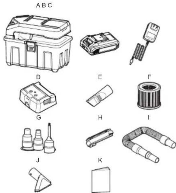
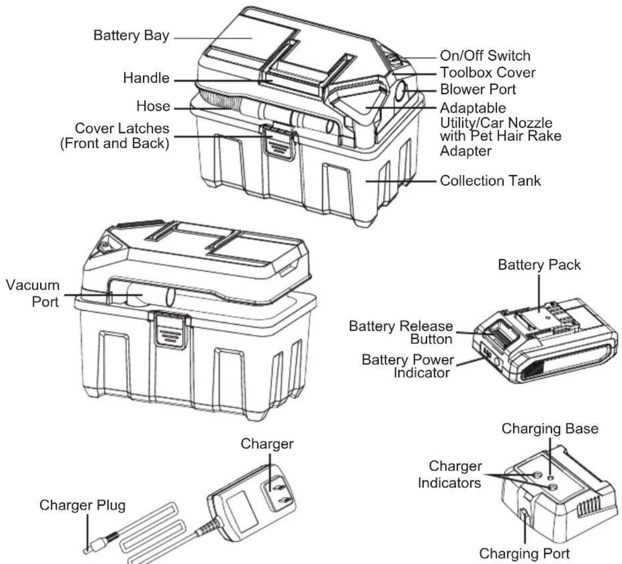
Remove all contents from the box. Remove the powerhead and take out any contents inside the collection tank. Check each item against the carton contents list.
Carton Contents List:
Key Description......Qty
A Vacuum Assembly.... 1
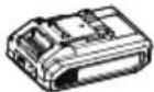
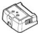
B Battery Pack.... 1
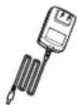
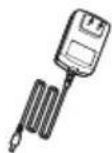
C Charger.... 1
D Charging Base.... 1
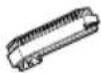
E 2-in-1 Crevice Tool with Brush.... 1
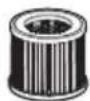
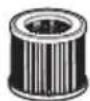
F Cartridge Filter.... 1
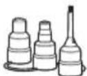
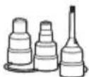
G Inflator Nozzle Adapter.... 1
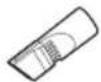
H Dust Brush Adapter.... 1
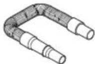
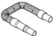
I Hose.... 1
J Adaptable Utility/Car Nozzle with Pet Hair Rake Adapter.... 1
K Operator's Manual.... 1
NOTE: The hose and accessories for this vacuum are 1-1/4" (32 mm) diameter.
GENERAL ASSEMBLY INSTRUCTIONS
natural_image
Line drawing of a mechanical device with a coiled pipe and housing (no text or symbols)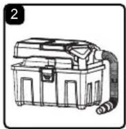
natural_image
Line drawing of a portable industrial machine with a coiled cable (no text or symbols)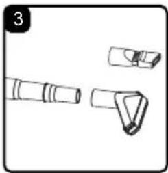
natural_image
Technical line drawing of three mechanical components (no text or symbols)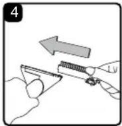
natural_image
Illustration of a hand using a tool to cut a triangular object with an arrow indicating direction (no text or symbols)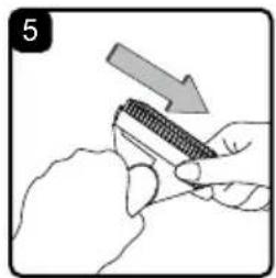
natural_image
Illustration of a hand holding a tool with a downward arrow indicating direction (no text or symbols)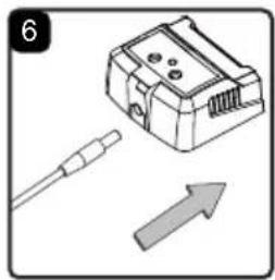
natural_image
Illustration of a device with a cable and an upward arrow, no text or symbols present- Verify that the battery pack is not installed.
- Undo the latches.
- Remove the contents from inside the collection tank; make sure you have all contents as listed on page 9.
INSTALLING & REMOVING THE HOSE
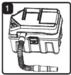
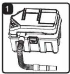
- Pull the work end of the hose out of the hose storage (Fig.1).
- The other end of the hose is already connected to the vacuum port; make sure it is secure.
- This wet/dry vacuum has blowing capabilities. To use as a blower, connect the larger end of the hose to the blower port (Fig. 2).
INSTALLING & REMOVING ACCESSORIES
Choose the desired accessories and push onto the smaller end of the hose (Fig. 3).
NOTE: This wet/dry vac comes with an adaptable utility/car nozzle. This accessory can be used as a wet nozzle, a brush, or a pet hair rake. To use the slide-on adapters follow these instructions:
- Choose the brush or the pet hair rake adapter.
- With the nozzle facing up, slide the adapter onto the utility/car nozzle until it clicks into place (Fig. 4).
- To remove, press the tab on the right side of the adapter and slide it off the utility/car nozzle (Fig. 5).
ASSEMBLING THE CHARGER
The charger comes assembled ready for use. If it is not assembled, insert the charger plug into the charging port on the charging base all the way to the stop (Fig. 6).
GENERAL OPERATION
text_image
1 Charger Indicator (Green) Charger Indicator (Red)NOTE: Please fully charge before first use.

WARNING: Use only with the charger recommended by the manufacturer.
BATTERY LED PANEL
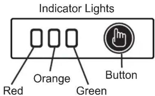
The panel consists of 3 LEDs on the battery. Press and hold the button, then release it, the LEDs will show you the charge levels.
The battery's charge level can be checked either when the battery is attached on the charger or removed from the charger.
| LEDs on Battery(Continuous Lighting) | Battery Capacity |
| 3 LEDs | 70-100% |
| 2 LEDs (orange & red) | 31-69% |
| 1 LED (red only) | 5-30% (Recharge required). |
text_image
Indicator Lights Red Orange Green ButtonNOTE: Recharge the battery at a temperature between 40^ F ( 4^ C) and 100^ F ( 40^ C). If the battery pack is hot, allow it to cool down before recharging.
CHARGER OPERATION
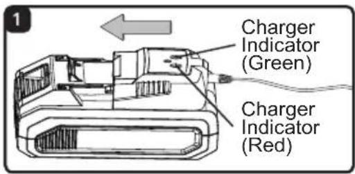
- Plug the charger into a wall outlet. The green charger indicator should turn on.
- Align the slot of the battery pack with the rail on the charger. Slide the charger onto the battery pack until it secures into place (Fig. 1). The red charger indicator should turn on.
- Allow for sufficient charging time. It may take up to 80 minutes to charge completely if fully drained.
- Once charging is completed, the red charger indicator should go off and the green charger indicator turns on. Disconnect the charger from the power supply and remove it from the battery pack.
NOTE: It is normal for the battery pack and the charger to become warm (but not hot) during charging process. If the battery does not charge properly, check to make sure the electrical outlet is operational. Always charge the battery before storage!
text_image
1 a 1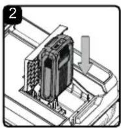
natural_image
Mechanical assembly diagram showing a device with a downward arrow, no visible text or symbols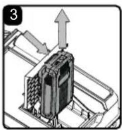
natural_image
Mechanical assembly diagram showing a component with an upward arrow indicating motion (no text or symbols present)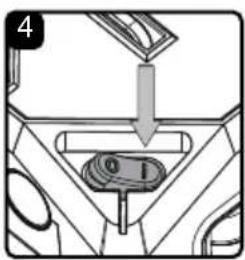
text_image
4 0 1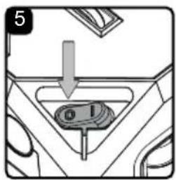
text_image
5 0 1The indicator lights on the charger show the charging status:
| Green Charger Indicator | Red Charger Indicator Status | |
| On | Off | Charger connected to power supply (Standby) |
| Off | On | Charging |
| On | Off | Fully charged |
After continuous or repeated charging cycles without interruption, the charger may warm up. This is normal and does not indicate a technical defect of the battery charger.

WARNING: Always charge the battery before storing! Please charge the battery to reach full or no less than half charge before storage. If the tool will not be used for long periods of time, charge the battery every 3-6 months.
It is important to disconnect the charger from the power supply after charging is finished.
Cool down the battery from a just-operated product for approximately 20 minutes before attempting to recharge.

WARNING: To reduce the risk of electric shock, this charger has a polarized plug (one blade is wider than the other). This plug will fit in a polarized outlet only one way. If the plug does not fit fully in the outlet, reverse the plug. If it still does not fit, contact a qualified electrician to install the proper outlet. Do not change the plug in any way.
INSTALLING & REMOVING BATTERY PACK
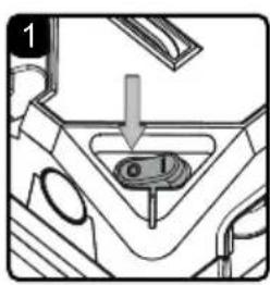
- Flip the ON/OFF switch to the 'O' OFF position (Fig. 1).
- Open the battery bay cover.
- To insert the battery pack, slide it into the battery bay until it snaps into place. A noticeable 'click' will be heard (Fig. 2).
- To remove the battery pack, press the battery release button and pull it out of the battery bay (Fig. 3).
STARTING/STOPPING THE WET/DRY VACUUM
To turn on the wet/dry vacuum, flip the switch to the 'I' ON position (Fig. 4). To turn off the wet/dry vacuum, flip the switch to the 'O' OFF position (Fig. 5).
$$ O = O F F \quad I = O N $$
natural_image
Technical illustration of a mechanical device with internal components and no visible text or symbols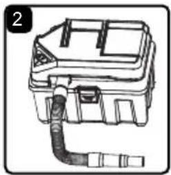
natural_image
Line drawing of a mechanical device with a coiled pipe or tube (no text or symbols)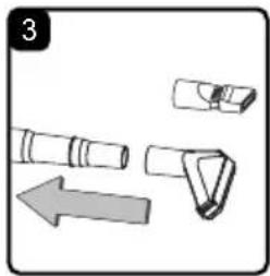
natural_image
Illustration of a mechanical device with a left-pointing arrow indicating direction (no text or symbols)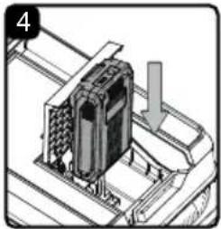
natural_image
Technical illustration of a mechanical assembly with a component and directional arrow (no text or symbols)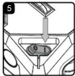
text_image
5 0 1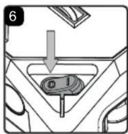
text_image
6 01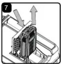
natural_image
Diagram of a mechanical component with directional arrows indicating movement or force (no text or symbols present)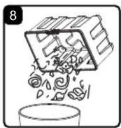
natural_image
Simple line drawing of a container with swirling contents and a box, no text or symbols present
WARNING: BE SURE TO READ, UNDERSTAND, AND APPLY INFORMATION ENTITLED "IMPORTANT SAFETY INSTRUCTIONS". DO NOT VACUUM IN AREAS WITH FLAMMABLE GASES, VAPORS, OR EXPLOSIVE DUSTS IN THE AIR. FLAMMABLE GASES OR VAPORS INCLUDE BUT ARE NOT LIMITED TO: LIGHTER FLUID, SOLVENT TYPE CLEANERS, OIL-BASED PAINTS, GASOLINE, ALCOHOL, OR AEROSOL SPRAYS. EXPLOSIVE DUSTS INCLUDE BUT ARE NOT LIMITED TO: COAL, MAGNESIUM, GRAIN, OR GUN POWDER. TO REDUCE THE RISK OF HEALTH HAZARDS FROM VAPORS OR DUST, DO NOT VACUUM TOXIC MATERIALS.
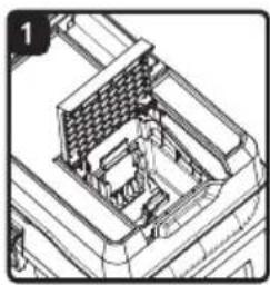
- Verify that the cartridge filter is securely mounted (Fig. 1). For installation instructions see page 18.
- Insert the hose into the vacuum port (Fig. 2).
- Push required accessory onto the free end of the hose (Fig. 3).
- Make sure the battery pack is correctly installed (Fig. 4). For installation instructions see page 12.
- Ensure the hose is securely held. Turn the vacuum on by flipping the switch to the 'I' position and begin vacuuming (Fig. 5).
- Once you have completed vacuuming, or when the collection tank is full, turn the vacuum off by flipping the switch to the 'O' OFF position (Fig. 6).
$$ O = O F F \quad I = O N $$
-
Remove the battery (Fig. 7).
-
Empty the collection tank into a suitable receptacle (Fig. 8).
natural_image
Technical illustration of a mechanical component with no visible text or symbols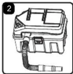
natural_image
Line drawing of a mechanical device with a coiled pipe and housing (no text or symbols)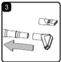
natural_image
Illustration of a mechanical component with an arrow indicating direction (no text or symbols)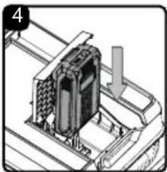
natural_image
Mechanical assembly diagram showing a component mounted on a conveyor belt with a downward arrow indicating motion (no text or symbols present)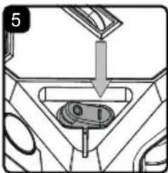
text_image
5 01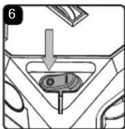
text_image
6 o 1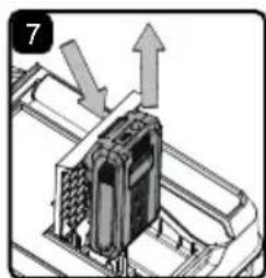
natural_image
Mechanical assembly diagram showing a component with arrows indicating motion (no text or symbols)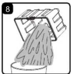
natural_image
Illustration of a bucket pouring liquid into a container with a container on top (no text or symbols)NOTE: The provided filter can be used for both wet and dry vacuum operation.
- Verify that the cartridge filter is securely mounted (Fig. 1). For installation instructions see page 18.
- Insert the hose into the vacuum port (Fig. 2).
- Push required accessory onto the free end of the hose (Fig. 3).
- Make sure the battery pack is correctly installed (Fig. 4). For installation instructions see page 12.
- Ensure the hose is securely held. Turn the vacuum on by flipping the switch to the 'I' position and begin vacuuming (Fig. 5).
- Once you have completed vacuuming, or when the collection tank is full, turn the vacuum off by flipping the switch to the 'O' OFF position (Fig. 6).
$$ O = O F F \quad I = O N $$
- Remove the battery (Fig. 7).
- Empty the collection tank, clean, and dry the inside and outside of the collection tank (Fig. 8).
IMPORTANT! When vacuuming large quantities of liquids, do not immerse the nozzle completely in the liquid; leave a gap at the tip of the nozzle opening to allow air inflow. The machine is fitted with a float valve that stops the suction action when the collection tank reaches its maximum capacity. You will notice an increase in motor speed. When this happens, turn off the machine, remove the battery pack, and drain the liquid into a suitable receptacle or drain. To continue vacuuming, refit the powerhead to the collection tank. After wet vacuuming, turn the machine off and remove the battery. Empty the collection tank, clean and dry the inside and outside before storage.
REMEMBER! The cartridge filter must be air dry and installed before dry vacuuming again.
BLOWER OPERATION
natural_image
Line drawing of a mechanical device with a coiled cable and housing (no text or symbols)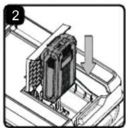
natural_image
Mechanical assembly diagram showing a component being inserted into a housing (no text or symbols visible)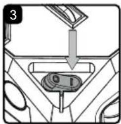
text_image
3 0 1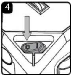
text_image
4 a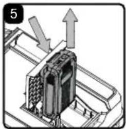
natural_image
Mechanical assembly diagram showing a component with arrows indicating motion (no text or symbols)This Wet/Dry Vacuum has blowing capabilities. To use the blower feature, follow the instructions listed below.

WARNING: ALWAYS WEAR SAFETY GOGGLES COMPLYING WITH ANSI Z87.1 (OR IN CANADA, CSAZ94.3) BEFORE USING BLOWER.

CAUTION: KEEP BYSTANDERS CLEAR FROM BLOWING DEBRIS.

WARNING! WEAR A DUST MASK IF BLOWING CREATES DUST THAT MIGHT BE INHALED.
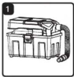
- Make sure the collection tank is empty before using as a blower. Clear all dirt and debris from the hose and collection tank.
- Connect the hose to the blower port (Fig. 1).
- Push required accessory onto the free end of the hose.
- Make sure the battery is correctly installed (Fig. 2). For installation instructions see page 12.
- Ensure the hose is securely held. Turn the vacuum on by flipping the switch to the "I" position (Fig. 3).
- Once you have completed blowing, turn the vacuum off by flipping the switch to the 'O' OFF position (Fig. 4).
- Remove the battery (Fig. 5).
INFLATOR NOZZLE ADAPTER OPERATION
natural_image
Line drawing of a portable electronic device with coiled cable and housing (no text or symbols)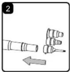
natural_image
Diagram showing three cylindrical objects with an arrow indicating direction (no text or symbols)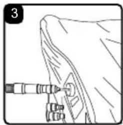
natural_image
Line drawing of a mechanical component with a tool inserted, no visible text or symbols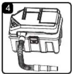
natural_image
Line drawing of a mechanical device with a coiled cable or pipe attached to a housing (no text or symbols)INFLATING AN OBJECT
The included inflator nozzle adapter allows any wet/dry vacuum with a blower function to be used to inflate items such as air mattresses and recreational floatation devices. These nozzles can also be used to focus the air flow, allowing for more concentrated blowing.
- Make sure the collection tank is empty before using the wet/dry vacuum to inflate.
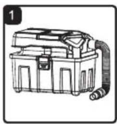
- Connect the hose to the blower port (Fig. 1).
- Push the desired inflator nozzle onto the free end of the hose (Fig. 2).
- Make sure the battery is correctly installed. For installation instructions see page 12.
- Insert the inflator nozzle into the air valve of the item being inflated (Fig. 3).
- Turn the vacuum on by flipping the switch to the 'I' position. Once you have completed inflating, turn the vacuum off by flipping the switch to the 'O' OFF position.
- Remove the battery.
DEFLATING AN OBJECT
- Connect the hose to the vacuum port (Fig. 4).
- Push the desired inflator nozzle onto the free end of the hose (Fig. 2).
- Make sure battery is correctly installed. For installation instructions see page 12.
- Insert the inflator nozzle into the air valve of the item being deflated.
- Turn the vacuum on by flipping the switch to the 'I' position. Once you have completed deflating, turn the vacuum off by flipping the switch to the 'O' OFF position.
- Remove the battery.
natural_image
Technical line drawing of a mechanical assembly with no visible text or symbols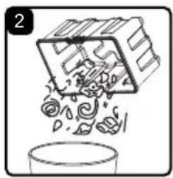
natural_image
Illustration of a container pouring liquid into a container with scattered papers (no text or symbols)
WARNING: TO REDUCE THE RISK OF INJURY, ALWAYS REMOVE THE BATTERY PACK FROM THE TOOL BEFORE PERFORMING ANY MAINTENANCE. NEVER DISASSEMBLE THE TOOL, BATTERY PACK OR CHARGER.
IMPORTANT! BEFORE CLEANING YOUR VACUUM OR CARRYING OUT ANY MAINTENANCE, MAKE SURE THAT THE TOOL IS SWITCHED OFF AND REMOVE THE BATTERY PACK TO PREVENT ACCIDENTAL START-UP.
EMPTYING & CLEANING THE COLLECTION TANK
- Verify that the battery has been removed from the battery bay (Fig. 1).
- Disconnect the hose from the vacuum.
- Undo the collection tank latches and remove the powerhead from the collection tank. Place powerhead on a soft, clean surface upside down.
- Clear all dirt or debris from the collection tank and clean with mild soap and water. Allow to dry before replacing the powerhead (Fig. 2).
STORAGE
Before storing your vacuum cleaner, the collection tank should be emptied and cleaned. The battery should be stored in a dry location. The accessories should be cleaned and stored so they can be readily available when needed. Store wet/dry vacuum indoors.
REPAIRS
Repairs for this wet/dry vacuum should be performed only by qualified service personnel using only identical replacement parts.
INSTALLING & CLEANING CARTRIDGE FILTER
natural_image
Technical line drawing of a mechanical assembly with no visible text or symbols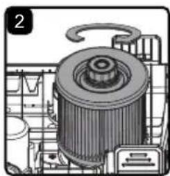
natural_image
Technical illustration of a mechanical assembly with gears and housing (no visible text or symbols)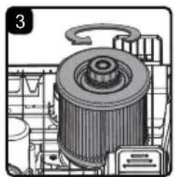
natural_image
Technical illustration of a mechanical component with no visible text or symbols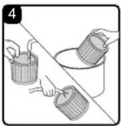
natural_image
Illustration of three buckets and a bucket being handled, no text or symbols presentINSTALLING CARTRIDGE FILTER
- Verify that the battery has been removed from the battery bay (Fig. 1).
- Remove powerhead and place in an upside-down position.
- Install the cartridge filter over the filter cage, securing it with the retainer nut. Do not over-tighten (Fig. 2).
REMOVING & CLEANING CARTRIDGE FILTER
- Unscrew the retainer nut by turning counterclockwise (Fig. 3).
- Carefully hold and pull the cartridge filter up for removal.
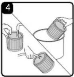
- Clean the cartridge filter by brushing or rinsing off the debris (Fig. 4).
- Install cleaned or new filter as instructed in steps 2 & 3 of INSTALLING CARTRIDGE FILTER.
- Allow the wet filter to air dry completely before storing or installing onto the filter cage.
ENVIRONMENTALLY SAFE BATTERY DISPOSAL

The following toxic and corrosive materials are in the batteries used in this battery pack: lithium-ion, a toxic material.

WARNING: All toxic materials must be disposed of in a specified manner to prevent contamination of the environment. Before disposing of damaged or worn out Lithium-Ion battery packs, contact your local waste disposal agency, or the local Environmental Protection Agency for information and specific instructions.

WARNING: If the battery pack cracks or breaks, with or without leaks, do not recharge it and do not use it. Dispose of it and replace with a new battery pack.
DO NOT ATTEMPT TO REPAIR IT!
To avoid injury and risk of fire, explosion, or electric shock, and to avoid damage to the environment:
- Cover the battery terminals with heavy-duty adhesive tape.
- DO NOT attempt to remove or destroy any of the battery pack components.
- DO NOT attempt to open the battery pack.
- If a leak develops, the released electrolytes are corrosive and toxic. DO NOT get the solution in the eyes or on skin, and do not swallow it.
- DO NOT place these batteries in your regular household trash.
- DO NOT incinerate.
- DO NOT place batteries where they will become part of any waste landfill or municipal solid waste stream.
- Take batteries to a certified recycling or disposal center.
TROUBLESHOOTING

WARNING! TO REDUCE THE RISK OF ELECTRIC SHOCK, REMOVE THE BATTERY PACK BEFORE TROUBLESHOOTING.
| PROBLEM POSSIBLE CAUSE SOLUTION | ||
| The vacuum will not operate. | Battery has no capacity. Charge the | battery. |
| Battery is not inserted properly. Insert battery pack correctly. | ||
| Wrong battery being used. | Be sure to use only the battery and charger supplied with your product. | |
| The vacuum power is weak. | There is a blockage in the hose and the tank inlet. | Check the hose and tank inlet for blockage. |
| The filter is clogged by fine dust. | Take off the filter and clean it or install a new filter. | |
| The collection tank is full. Empty the | collection tank. | |
| Low battery capacity. Charge the battery. | ||
| The vacuum turns off on its own. | No battery capacity. Charge the battery. | |
| Battery may be depleted. Change the battery. | ||
| The dust escapes from vacuum. | Filter is missing or installed incorrectly. | Check the filter for correct installation. |
| Filter is damaged. Replace the filter | ||
EXPLODED VIEW
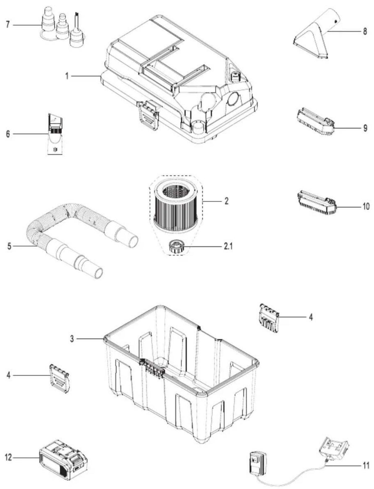
PARTS LIST
| Part Part Number Description Quantity | |||
| 1 Vacuum Assembly 1 | |||
| 2 551346102 Cartridge Filter 1 | |||
| 2.1 551346103 Retainer nut 1 | |||
| 3 Collection Tank 1 | |||
| 4 551346105 | Latch 2 | ||
| 5 | 551346110 | Hose | 1 |
| 6 | 551346112 | 2-in-1 Crevice Tool with Brush | 1 |
| 7 | 551346111 | Inflator Nozzle Adapter | 1 |
| 8 551346106 | Adaptable Utility/Car Nozzle 1 | ||
| 9 | 551346114 | Pet Hair Rake Adapter | 1 |
| 10 | 551346113 | Dust Brush Adapter | 1 |
| 11 | 541034102 | Charger Assembly | 1 |
| 12 | 541034103 | Battery | 1 |
SOMMAIRE
SECTION PAGE
Garantie....24
natural_image
Line drawing of a toolbox-like container with multiple compartments (no text or symbols)D

G
J

E
H
K

F
|
INSTRUCTIONS RELATIVES AU MONTAGE GÉNÉRAL
natural_image
Diagram of a mechanical device with a coiled pipe and housing (no text or symbols)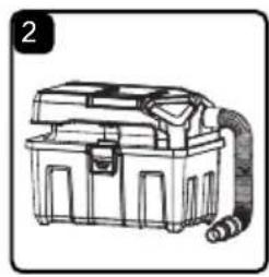
natural_image
Illustration of a portable electronic device with a coiled cable and handle (no text or symbols)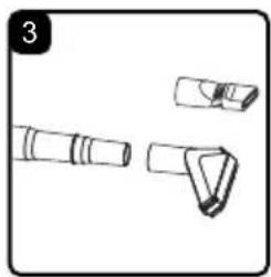
natural_image
Technical line drawing of three mechanical components (no text or symbols)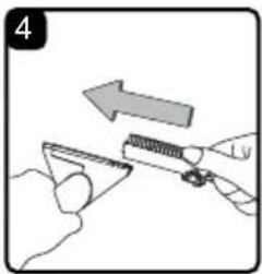
natural_image
Illustration of a hand holding a tool with an arrow indicating direction (no text or symbols)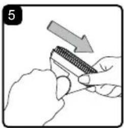
natural_image
Illustration of hands using a tool to adjust a textured object, with an arrow indicating direction (no text or symbols)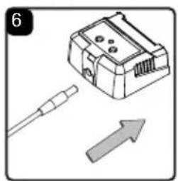
natural_image
Illustration of a device with a cable and an arrow, no text or symbols presentnatural_image
Mechanical assembly diagram showing a component being lowered into a conveyor belt (no text or symbols visible)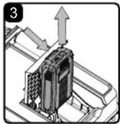
natural_image
Mechanical assembly diagram showing a component with upward force arrows (no text or symbols)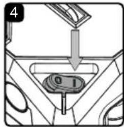
text_image
4 0 1
text_image
5 0 1natural_image
Technical illustration of a mechanical component with no visible text or symbols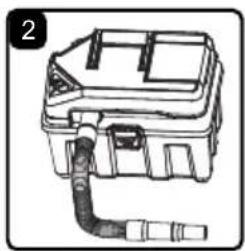
natural_image
Line drawing of a mechanical device with a coiled cable or plug, no text or symbols present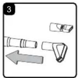
natural_image
Illustration of a mechanical device with an arrow indicating direction (no text or symbols)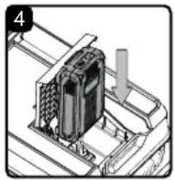
natural_image
Mechanical assembly diagram showing a device mounted on a conveyor belt with an arrow indicating motion (no text or symbols)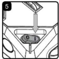
text_image
5 0 1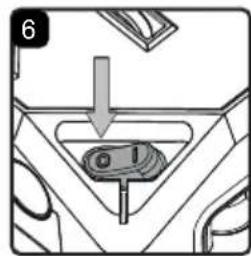
text_image
6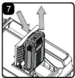
natural_image
Mechanical component with directional arrows indicating movement or force (no text or symbols)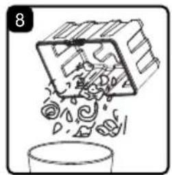
natural_image
Illustration of a container with swirling contents and a box of contents, no text or symbols presentAVERTISSEMENT : VEILLEZ À LIRE, À ASSIMILER ET À METTRE EN APPLICATION LES CONSIGNES INTITULÉES « CONSIGNES IMPORTANTES DE SÉCURITÉ ». NE PAS UTILISER L'ASPIRATEUR DANS DES ZONES OÙ L'AIR CONTIENT DES GAZ ET VAPEURS INFLAMMABLES OU DES POUSSIÈRES EXPLOSIVES. LES GAZ OU VAPEURS INFLAMMABLES COMPRENNENT, SANS POUR AUTANT S'Y LIMITER : L'ESSENCE POUR BRIQUETS, LES PRODUITS DE NETTOYAGE DE TYPE SOLVANTS, LA PEINTURE À L'HUILE, L'ESSENCE, L'ALCOOL OU LES SPRAYS AÉROSOLS. LES POUSSIÈRES EXPLOSIVES COMPRENNENT, SANS POUR AUTANT S'Y LIMITER : LE CHARBON, LE MAGNÉSIUM, LES GRAINS OU LA POUDRE À CANON. AFIN DE RÉDUIRE LES RISQUES POUR LA SANTÉ PROVENANT DES VAPEURS OU POUSSIÈRES, N'ASPIREZ PAS DE MATIÈRES TOXIQUES.
$$ O = O F F \quad I = O N $$
natural_image
Technical illustration of a mechanical component with no visible text or symbols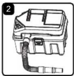
natural_image
Line drawing of a mechanical device with a coiled cable or pipe inserted (no text or symbols)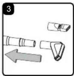
natural_image
Diagram showing three mechanical components with an arrow indicating direction (no text or symbols)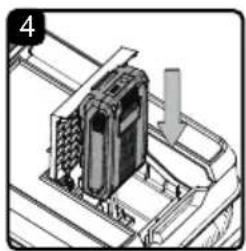
natural_image
Technical illustration of a mechanical assembly with a component and directional arrow (no text or symbols)
text_image
5 0 1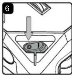
text_image
6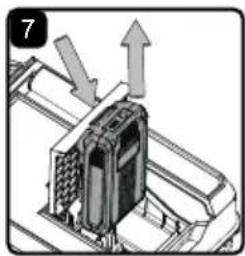
natural_image
Mechanical assembly diagram showing a device with directional arrows indicating motion (no text or symbols)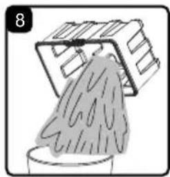
natural_image
Illustration of a hand washing clothes in a container with a box partially inserted (no text or symbols)$$ O = O F F \quad I = O N $$
natural_image
Line drawing of a portable electronic device with a coiled cable and housing (no text or symbols)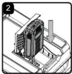
natural_image
Mechanical assembly diagram showing a component with a downward arrow, no visible text or symbols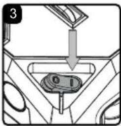
text_image
3 0 1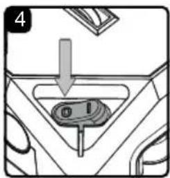
text_image
4 01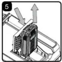
natural_image
Diagram of a device with upward arrows indicating motion or force, no visible text or symbolsnatural_image
Line drawing of a mechanical device with a coiled cable and housing (no text or symbols)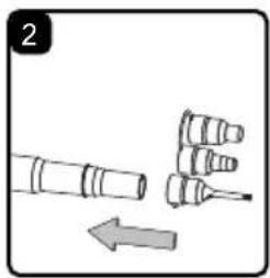
natural_image
Diagram showing three cylindrical objects with an arrow indicating direction (no text or symbols)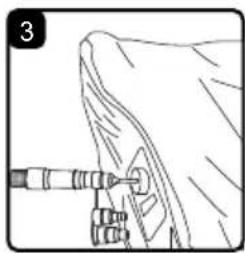
natural_image
Line drawing of a mechanical assembly with a tool and component (no text or symbols)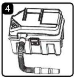
natural_image
Line drawing of a mechanical device with a coiled pipe and housing (no text or symbols)INFLATING AN OBJECT
natural_image
Isometric technical diagram of a mechanical assembly with no visible text or symbols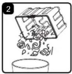
natural_image
Illustration of a box pouring liquid into a container (no text or symbols)
AVERTISSEMENT! POUR RÉDUIRE TOUS RISQUES DE BLESSURES, DÉBRANCHEZ TOUJOURS LE CHARGEUR, PUIS ENLEVEZ LE BLOC-BATTERIE DU CHARGEUR OU DE L'OUTIL AVANT DE PROCÉDER À TOUT ENTRETIEN. NE JAMAIS DÉMONTER L'OUTIL, LE BLOC-BATTERIE OU LE CHARGEUR.
IMPORTANT! AVANT DE NETTOYER VOTRE ASPIRATEUR OU D' EFFECTUER TOUT ENTRETIEN, ASSUREZ-VOUS QUE L'OUTIL EST MIS HIRS TENSION, PUIS RETIREZ LE BLOC-BATTERIE POUR PRÉVENIR TOUT RISQUE DE MISE EN MARCHE ACCIDENTELLE.
VIDANGE ET NETTOYAGE DU RÉSERVOIR COLLECTEUR
natural_image
Technical line drawing of a mechanical assembly with no visible text or symbols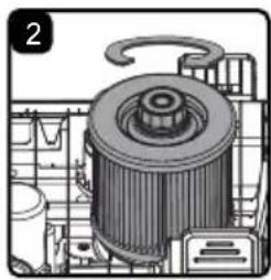
natural_image
Technical illustration of a mechanical component with no visible text or symbols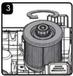
natural_image
Technical illustration of a mechanical component with no visible text or symbols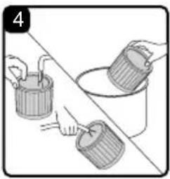
natural_image
Illustration of two buckets being placed on a surface, one with a straw and the other with a bucket (no text or symbols)INSTALLATION DU FILTRE CARTOUCHE
REMOVING & CLEANING CARTRIDGE FILTER
natural_image
Line drawing of a toolbox-like container with multiple compartments (no text or symbols)D
G
J


E

H

K

F
|
natural_image
Line drawing of a mechanical device with a coiled pipe and housing (no text or symbols)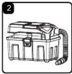
natural_image
Illustration of a portable electrical box with a coiled cable (no text or symbols)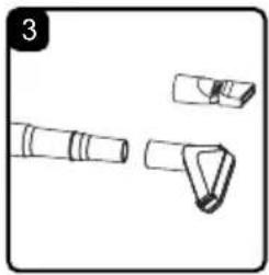
natural_image
Technical line drawing of three mechanical components (no text or symbols)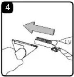
natural_image
Illustration of a hand holding a tool with an arrow indicating direction, no text or symbols present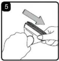
natural_image
Illustration of hands using a tool to cut a textured object with an arrow indicating direction (no text or symbols)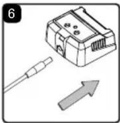
natural_image
Illustration of a connector with a cable and an upward arrow, no text or symbols presentnatural_image
Mechanical assembly diagram showing a device mounted on a platform with an arrow indicating motion (no text or symbols present)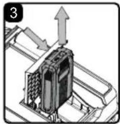
natural_image
Mechanical assembly diagram showing a component with upward force arrows (no text or symbols)
text_image
4 0 1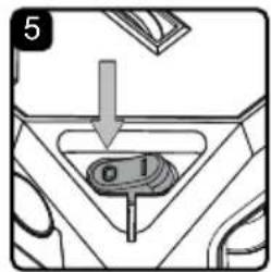
text_image
5 0 1natural_image
Technical illustration of a mechanical component with no visible text or symbols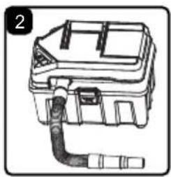
natural_image
Line drawing of a mechanical device with a coiled cable or plug, no text or symbols present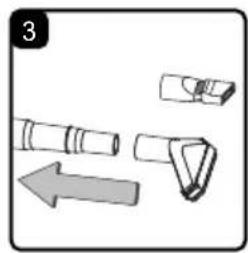
natural_image
Illustration of a mechanical device with an arrow indicating direction (no text or symbols)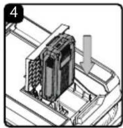
natural_image
Diagram of a mechanical device with a downward arrow indicating motion (no text or symbols present)
text_image
5 0 1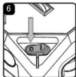
text_image
6 6 1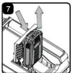
natural_image
Mechanical assembly diagram showing a device with arrows indicating motion or force (no text or symbols present)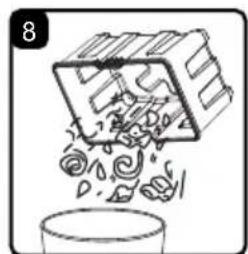
natural_image
Illustration of a container pouring liquid into a container with swirling patterns (no text or symbols)natural_image
Technical illustration of a mechanical assembly with gears and components (no visible text or symbols)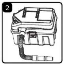
natural_image
Line drawing of a mechanical device with a coiled pipe or tube inserted (no text or symbols)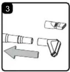
natural_image
Illustration of mechanical components with an arrow indicating direction (no text or symbols)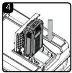
natural_image
Mechanical assembly diagram showing a device mounted on a base plate with a downward arrow indicating motion (no text or symbols present)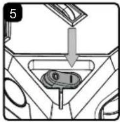
text_image
5 0 1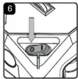
text_image
6 @ 1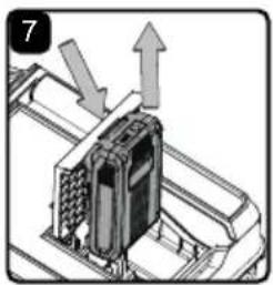
natural_image
Diagram of a mechanical component with arrows indicating direction (no text or symbols)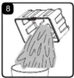
natural_image
Illustration of a person pouring liquid from a container into a container with a container partially visible (no text or symbols)$$ O = A P A G A D O \quad I = E N C E N D I D O $$
natural_image
Line drawing of a portable electronic device with a coiled cable and housing (no text or symbols)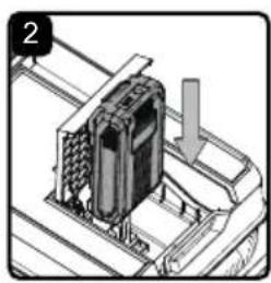
natural_image
Mechanical assembly diagram showing a component with a downward arrow, no visible text or symbols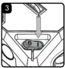
text_image
3 0 1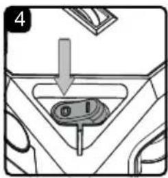
text_image
4 01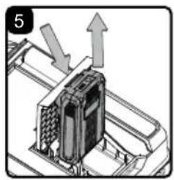
natural_image
Diagram of a mechanical device with upward arrows indicating motion or force (no text or symbols present)natural_image
Illustration of a portable electronic device with a coiled cable and handle (no text or symbols)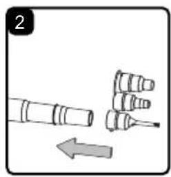
natural_image
Diagram showing two cylindrical objects with a downward arrow indicating motion or movement (no text or symbols)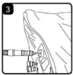
natural_image
Line drawing of a mechanical assembly with a tool inserted into a component (no text or symbols)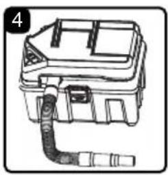
natural_image
Line drawing of a mechanical device with a coiled pipe and housing (no text or symbols)CÓMO INFLAR UN OBJETO
natural_image
Isometric technical drawing of a mechanical assembly with no visible text or symbols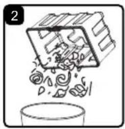
natural_image
Illustration of a box pouring liquid into a container (no text or symbols)
natural_image
Technical line drawing of a mechanical assembly with no visible text or symbols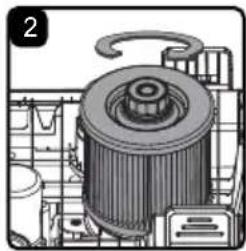
natural_image
Technical illustration of a mechanical component with no visible text or symbols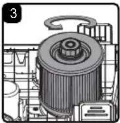
natural_image
Technical illustration of a mechanical component with no visible text or symbols