Mini Pure'line 800996 - Range hood NOVY - Free user manual and instructions
Find the device manual for free Mini Pure'line 800996 NOVY in PDF.


User questions about Mini Pure'line 800996 NOVY
0 question about this device. Answer the ones you know or ask your own.
Ask a new question about this device
Download the instructions for your Range hood in PDF format for free! Find your manual Mini Pure'line 800996 - NOVY and take your electronic device back in hand. On this page are published all the documents necessary for the use of your device. Mini Pure'line 800996 by NOVY.
USER MANUAL Mini Pure'line 800996 NOVY
EN Installation Instructions p. 47
Novy
800996
INHOUD
1 VOORSCHRIFTEN VOOR VEILIGHEID EN MONTAGE 3
-
ACCESSOIRES 6
-
INSTALLATIE 7
1VOORSCHRIFTENVOOR VEILIGHEID EN MONTAGE
natural_image
Diagram of a mobile phone with a diagonal line crossing it, no text or symbols present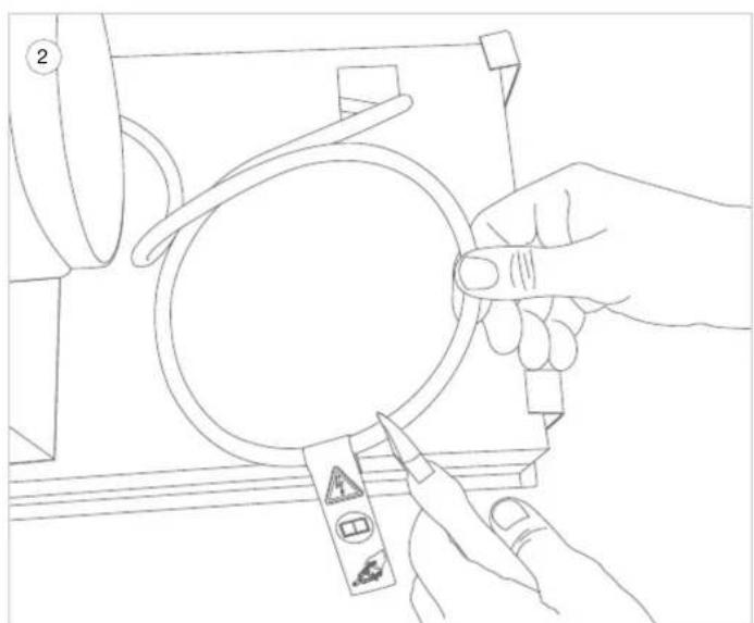
natural_image
Line drawing of hands holding a magnifying glass over a mechanical component (no text or symbols)natural_image
Line drawing of two hands holding a small cylindrical object, no text or symbols presentnatural_image
Line drawing showing hands holding a wire being inserted into a pliers (no text or symbols present)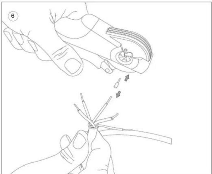
natural_image
Line drawing showing two hands performing a manual tool manipulation technique (no text or symbols present)natural_image
Technical line drawing of a mechanical device with internal components and mounting holes (no text or symbols)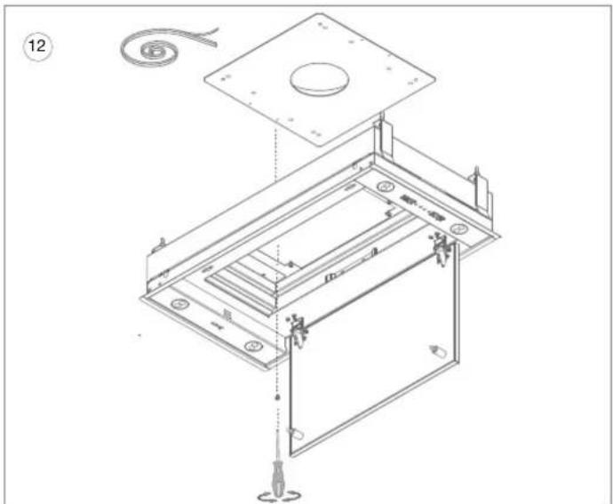
text_image
Technical diagram of an open device with labeled components and assembly steps, including screwdriver and cable connection.natural_image
Technical line drawing of a mechanical housing or enclosure with mounting flanges and a central circular component (no text or symbols)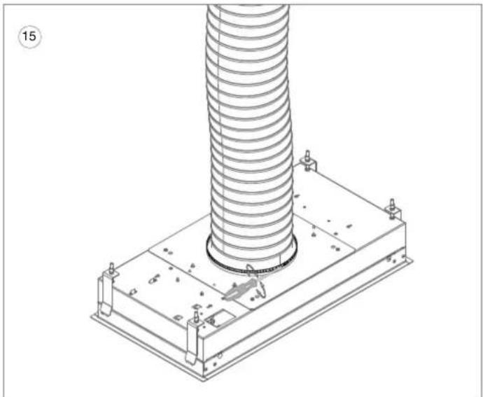
natural_image
Technical line drawing of a mechanical assembly with a coiled spring mounted on a base plate (no text or symbols)natural_image
Diagram of a mobile phone with a diagonal line crossing it, no text or symbols present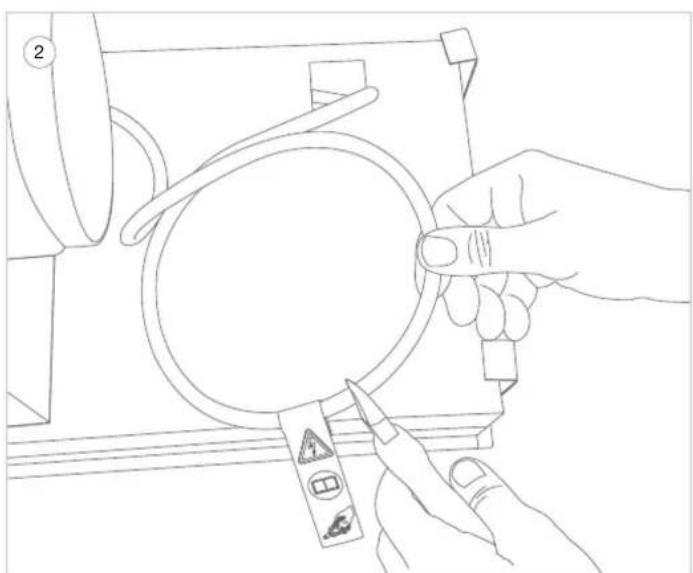
natural_image
Line drawing of hands holding a magnifying glass over a mechanical component (no text or symbols)natural_image
Line drawing of two hands holding a small cylindrical object, no text or symbols presentnatural_image
Line drawing of two hands holding a wire tool, one open showing internal components, the other holding a cable (no text or symbols)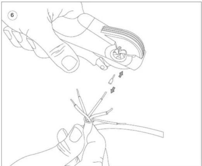
natural_image
Line drawing showing two hands performing a manual tool manipulation technique (no text or symbols present)natural_image
Technical line drawing of a mechanical device with internal components and mounting holes (no text or symbols)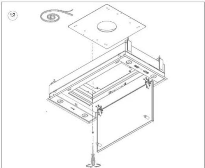
text_image
Technical diagram of an open electronic device with labeled components and assembly stepsnatural_image
Technical line drawing of a mechanical housing or enclosure with mounting flanges and a central circular component (no text or symbols)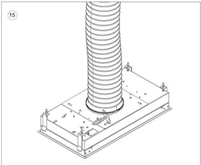
natural_image
Technical line drawing of a mechanical assembly with a coiled spring mounted on a base plate (no text or symbols)natural_image
Diagram of a mobile phone with a diagonal line crossing it, no text or symbols present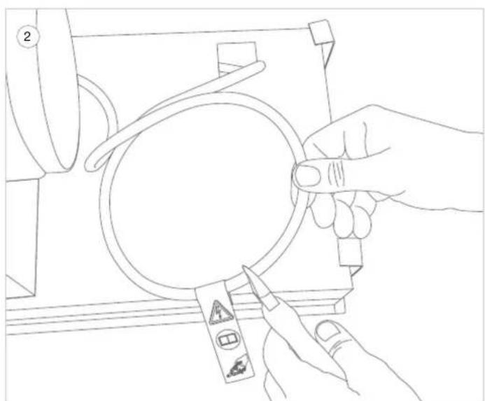
natural_image
Line drawing of hands holding a magnifying glass over a mechanical component (no text or symbols)natural_image
Line drawing of two hands holding a small cylindrical object, no text or symbols presentnatural_image
Line drawing showing hands holding a wire being inserted into a pliers (no text or symbols present)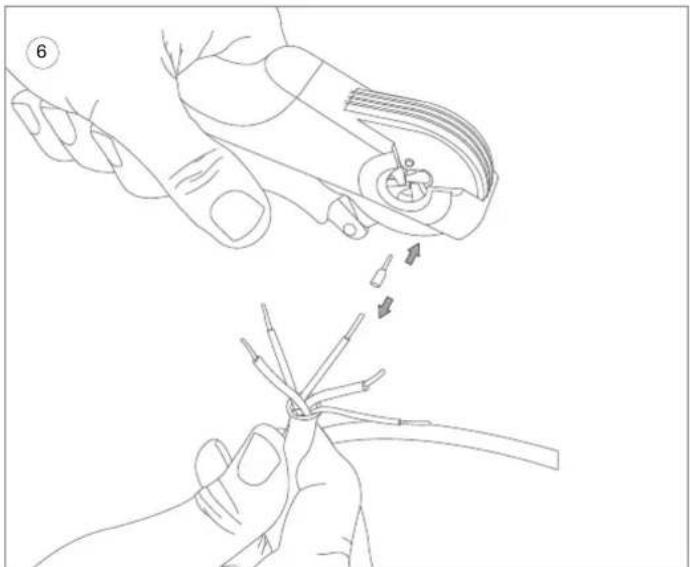
natural_image
Line drawing showing two hands performing a manual tool manipulation technique (no text or symbols present)natural_image
Technical line drawing of a mechanical device with internal components and mounting holes (no text or symbols)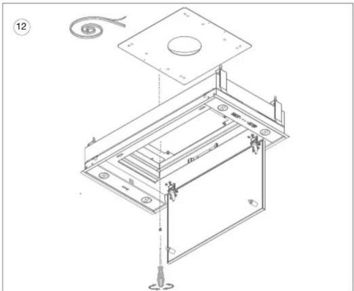
text_image
Technical diagram of an open device with labeled components and assembly steps, including screwdriver and cable connection.natural_image
Technical line drawing of a mechanical housing or enclosure with mounting flanges and a central circular component (no text or symbols)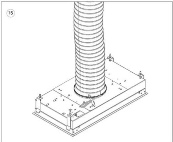
natural_image
Technical line drawing of a mechanical assembly with a coiled spring mounted on a base plate (no text or symbols)- SAFETY AND ASSEMBLY REGULATIONS 48
- ACCESSORIES 51
- INSTALLATION 52
1. SAFETY AND ASSEMBLY REGULATIONS
These are the mounting instructions for the Novy appliance shown on the cover. Carefully read the safety instructions, mounting instructions and user manual before installation and putting it into operation.
The safety instructions are listed in a separate booklet supplied with the appliance and listed on our website www.novy.com.
Follow the safety instructions, mounting instructions and user manual to prevent injury and material damage.
This manual makes use of a number of symbols. The meaning of these symbols are given below.
| Symbol | Meaning Action | |
 | Indication Explanation of an indication on the appliance. | |
 | Information/warning | This symbol indicates an important tip or a dangerous situation. |
Exhaust or recirculation
Before starting to install, you need to have decided whether you are making an extraction duct to the outside, or whether you are going to use the extractor hood as a recirculation extractor hood. If opting for recirculation, you will find the recirculation kit with the accessories in these installation instructions.
Install the exhaust duct
For optimum performance of the cooker hood it is important to pay attention to the following points:
The motor outlet has a diameter of 150 mm. It is recommended to connect an exhaust duct with a diameter of 150 mm to this.
You will achieve the best operation and lowest possible noise level for the appliance by connecting the extraction duct by as short a route as possible, with as few bends as possible and using the prescribed diameter.
- Use smooth, non-flammable pipes with an internal diameter that is equal to the external diameter of the connection nozzle of the hood.
Use flat duct with rounded corners and with air deflectors. Available at Novy.
- Do not reduce the exhaust diameter. This will lower the capacity and raise the noise level.
Avoid right-angle bends. Use rounded bends for effective airflow.
Use of a flexible extraction hose should be kept to a minimum, and it should only be used for making small bridging sections, for example as the link between the outlet nozzle and the extraction duct. Maximally extend flexible ducts and cut them to size.
- Ensure that the extraction duct is not crushed and that there are no kinks in the duct.
Use a hose clamp or aluminum tape for airtight connections.
With a horizontal extraction duct, install it at a slight incline to ensure that condensation does not run back to the appliance.
- Condensation may arise as a result of temperature differences if the extraction duct passes through cool rooms. Ensure that the extraction duct is insulated.
– In case of an exhaust pipe through the outside wall passing a cavity wall, make sure that the exhaust duct fully bridges the cavity and slightly declines to the outside.
– In case of an exhaust pipe through the wall, use a wall vent.
– In case of an exhaust pipe through the roof, use a double-walled roof passage with adequate outlet capacity.
- When connecting to a short extraction duct, it may be desirable to install a non-return valve in the duct in order to prevent backdraught from wind.
Make sure that sufficient air is supplied. Fresh air can be supplied by slightly opening a window or an outside door or by installing an inlet grate.
The appliance may not be connected to a flue or chimney that is currently in use, or that serves as ventilation for rooms with hearths.
When using the appliance with an internal or external motor (unit) with air extraction to the outside, there must be adequate air supply in the room where the appliance has been installed / is positioned, so that fresh air can flow in.
With an appliance with recirculation, there must be a minimum of ventilation in the room where the appliance has been installed / is positioned. Ventilation can be provided by the overall ventilation in the home or by tilting a window or opening a door.
2. ACCESSORIES
Recirculation
If you choose recirculation, Novy offers the outlet box in various sizes, including type 841400 / 842400 / 843400 or type 7931400 / 7932400 / 7933400.
Extension cable
When mounting the motor unit remotely, it may be desirable to place a longer cable between the hood and motor. The extension cable is connected to the existing cable (7000094).
Accessories circular exhaust tube
– Circular exhaust tube 906415
length 1000 mm ∅ 150 mm
- Connection piece ∅ 150 mm 906417
– Curve 90° ∅ 150 mm 906416
– Aluminium external grill for ∅ 150 mm 906178
– Wall conduct kit for ducting ∅ 150 mm including built-in heat retention 906420 non-return valve
- Non-return valve ∅ 150 mm 906432
Accessories flat exhaust duct
- Flexible exhaust tube length 750 mm 906408
- Flat exhaust channel duct 1000 mm 906401
(dimensions: 89 x 222 x 1000 mm) -
Connection piece (dimensions: 906402 94 × 227 × 80 ~mm )
– Horizontal curve 906403
(dimensions: 94 x 227 x 290 mm) -
Vertical curve 906404
(dimensions: 94 x 175 x 227 mm) - Curve 15^ 906418
(dimensions: 94 x 227 x 138 mm) - Corner adapter 906405
(dimensions: 94 x 227 x 205 mm) - Transition piece to ∅ 150 mm 906406
(dimensions: 94 x 227 x 190 mm) 906425
– Wall conduct kit for flat exhaust duct 89 x 222mm including built-in heat retention non-return valve - Stainless Steel blind grill with non-return 906407 valve (dimensions: 290 x 160 mm)
General accessories
- Hose clamp adjustment ∅ 60-215 mm 906291
– Aluminium tape roll 50 m 906292
Further information on Novy products, accessories and services may be found on the internet: www.novy.com.
3.INSTALLATION
A
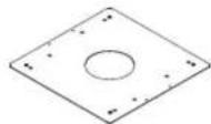
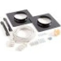
2× 820828

12× 906116
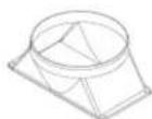
1x 864006
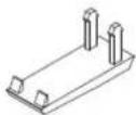
1x 6830046 2x 830822
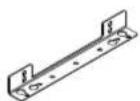
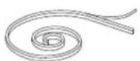
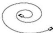
1x 9903981x 801006
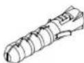
4x 906055
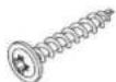
4x 906192
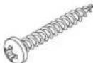
4×906143
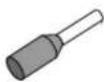
8x 7903180
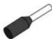
2x 6830181
This kit can only be installed in combination with the Novy Mini Pureline.
Carefully read the safety and installation instructions of this kit and of the built-in unit before installing and using it.
Make sure that the wall against which the motor unit is installed has sufficient load bearing capacity.
The motor unit must be installed indoors.
The installation and electrical connection of the appliance may only be carried out by an authorised specialist.
natural_image
Diagram of a mobile phone with a diagonal line crossing it, no text or symbols present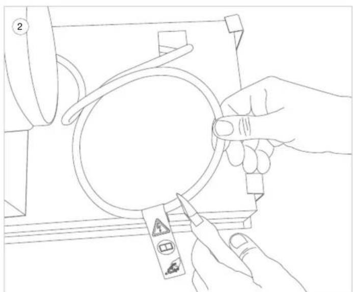
natural_image
Line drawing of a hand holding a magnifying glass over a mechanical component (no text or symbols)Caution, do not perform any of the following operations while the unit is energised. Make sure that the power is off or that the plug of the cooker hood is unplugged.
The following adjustments to the electrical connection of the unit may only be carried out by an authorised specialist.
① Make sure that the cooker hood is disconnected from the power supply.
② The motor cable is located between the built-in unit and the motor unit.
Cut this cable at the level of the sticker.
text_image
3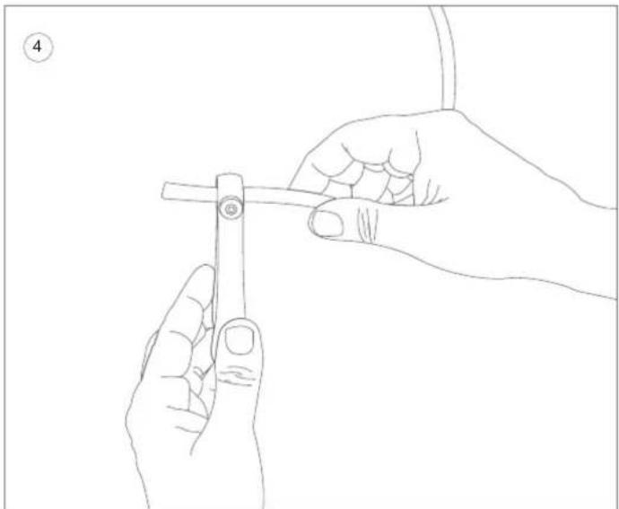
natural_image
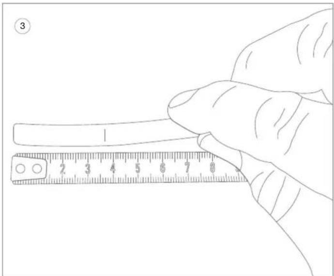
Line drawing of two hands holding a small cylindrical object, no text or symbols present③ Remove 37 mm of cable insulation from both ends of the cut motor cable.
④ From the loose wire ends cut off the red wire and 2 white filler wires (= WITHOUT CORE) up to the cable insulation.
natural_image
Line drawing showing hands holding a wire tool and a pliers (no text or symbols)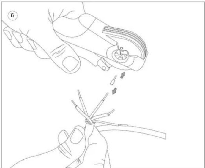
natural_image
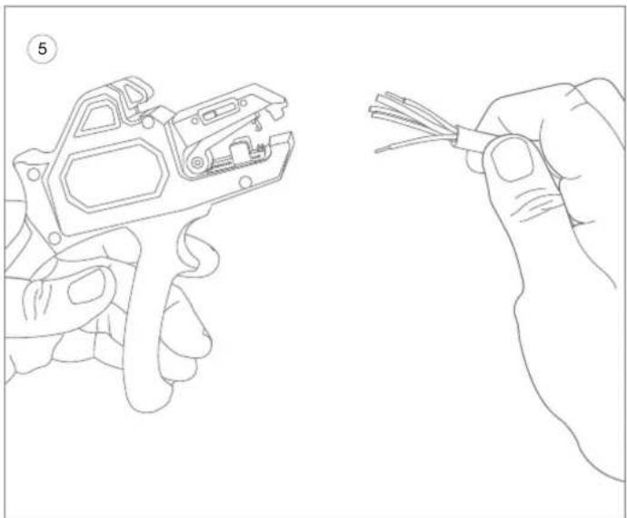
Line drawing showing two hands performing a manual tool manipulation technique (no text or symbols present)⑤ Strip the wire insulation of the remaining wires 8 mm with a stripping tool.
⑥ Apply the wire end ferrules (8x7903180 and 2x 6830181) to all wires and fix with a plier. Please note that the larger end ferrule (6830181) is reserved for the yellow/green wire.

text_image
Male 6830045 Strain relief 6830046 Female 6830044 BL WT GE/GN GS ZW 990398 BL WL GE/GN GS ZW BL WL GE/GN GS ZW 990398 bleu blau weiss gelb/grün grau schwarz blue white yellow/green grey black⑦ Connect the supplied connectors (6830044 and 6830045) to the wires.
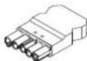
Fit the Female connector (6830044) to the cable coming from the the built-in unit.
Fit the Male connector (6830045) to the cable leading to the motor unit.
⑧ Position the wires and screw them on as shown in drawing 8.
This is necessary for the proper operation and to avoid damaging the cooker hood.
Close the covers of the connectors and screw them on. This is also the strain relief for the cables.
text_image
Extension cable 990398 Strain relief 6830046 Strain relief 6830046 Female 6830044 Male 6830045 Motor unit Ceiling unit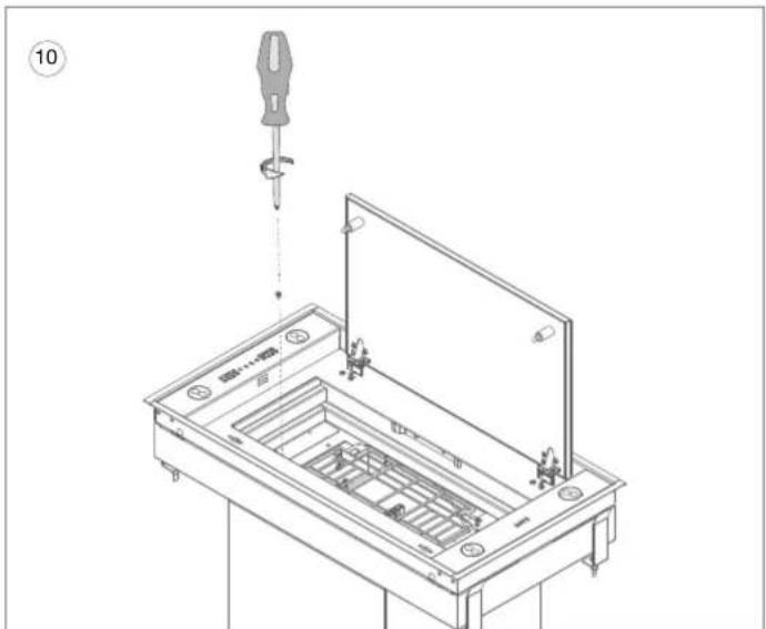
text_image
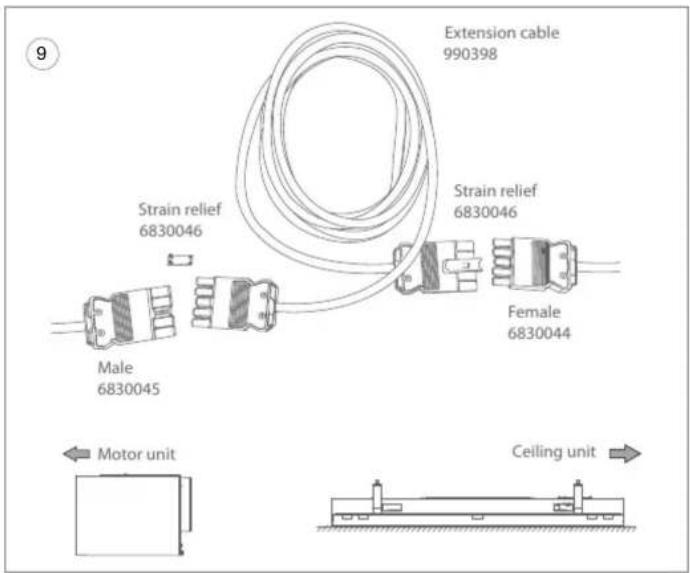
10 #...#⑨ Everything is now ready to connect the extension cable (990398) to the connectors of the built in unit and the motor unit (see step 16).
⑩ Uninstall the motor unit of the built-in unit.
- Open the bottom plate and remove the grease filter. If a recirculation filter is present, remove it also.
- Loosen the screws located next to the protective grid. The motor unit is now disconnected from the cooker hood.
natural_image
Technical line drawing of a mechanical device with internal components and mounting holes (no text or symbols)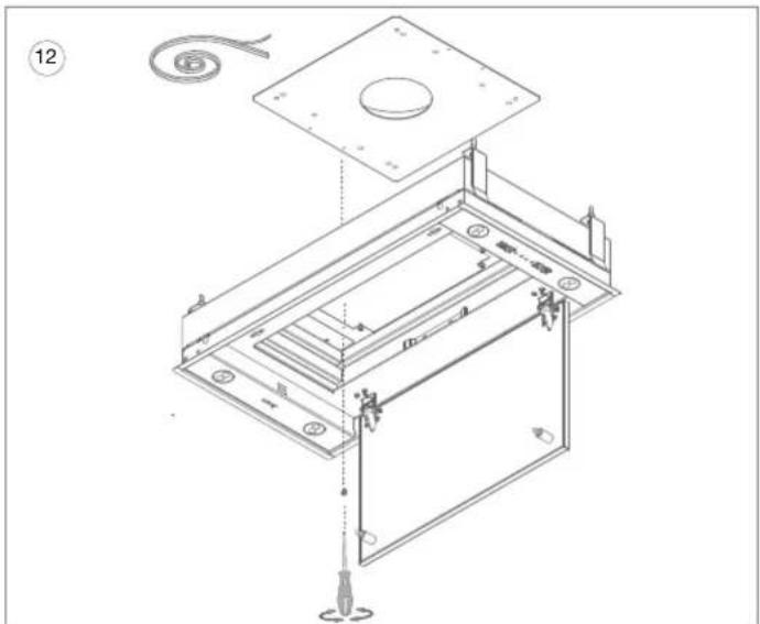
text_image
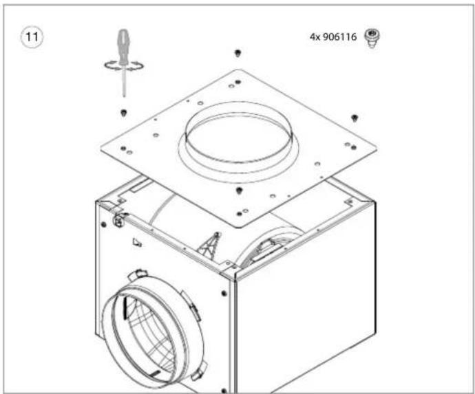
Technical diagram of an open electronic device with labeled components and assembly steps⑪ Screw the flange plate (820828) onto the motor unit with 4 of the supplied screws (906116).
12 Stick the supplied insulating strip (801006) on the underside of the other flange plate (820828). Then screw this flange plate to the built in unit using 4 of the screws supplied (906116).
text_image
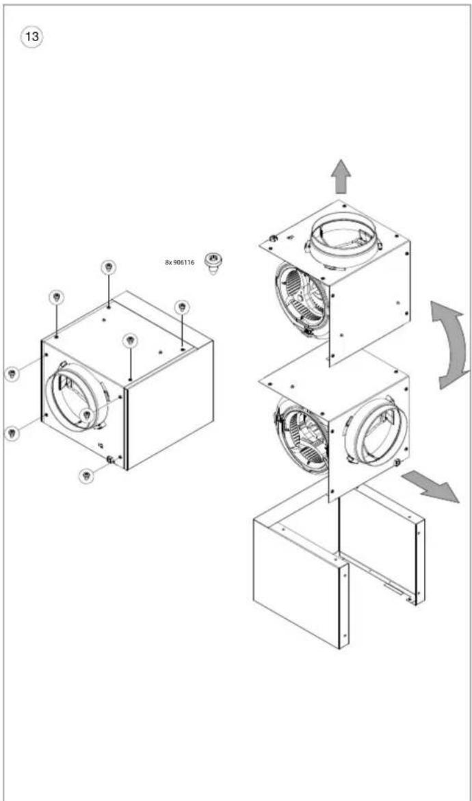
13 8x90611613 Determine the place where you want to place/ hang the motor unit. If necessary, the exhaust direction of the motor unit can be changed by removing 8 screws from the motor cover and turning the motor cover a quarter turn.
Before fastening the 2 brackets (830822), remove the screws of the motor cover on the side on which you want the suspension brackets to be placed. Attach the suspensions brackets onto the motor unit using the original screws.
natural_image
Technical line drawing of a mechanical housing or enclosure with mounting flanges and a central circular component (no text or symbols)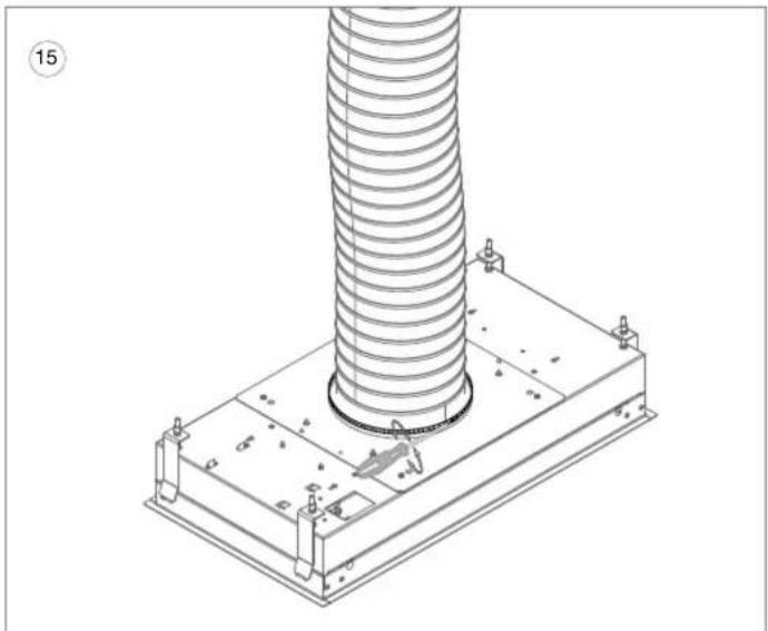
natural_image
Technical line drawing of a mechanical assembly with a coiled spring mounted on a base plate (no text or symbols)Mount the built-in unit in the recess as described in the installation instructions of the concerned built-in unit.
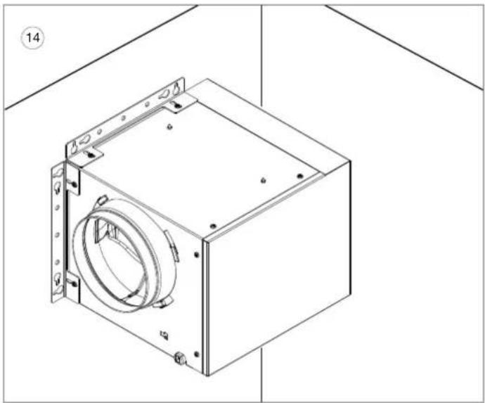
14 Install the motor unit onto the wall. Attention! Do not attach the motor to the ceiling. For this use the supplied screws and any plugs, if necessary. The supply and exhaust pipes can be made in a 90° angle or in a straight line.
15 Use for all hood models a duct of ∅150 mm between the built-in unit and the motor unit. Attach the exhaust duct to the flange plate on the build-in unit and on the motor unit using a hose clamp or aluminium tape.
text_image
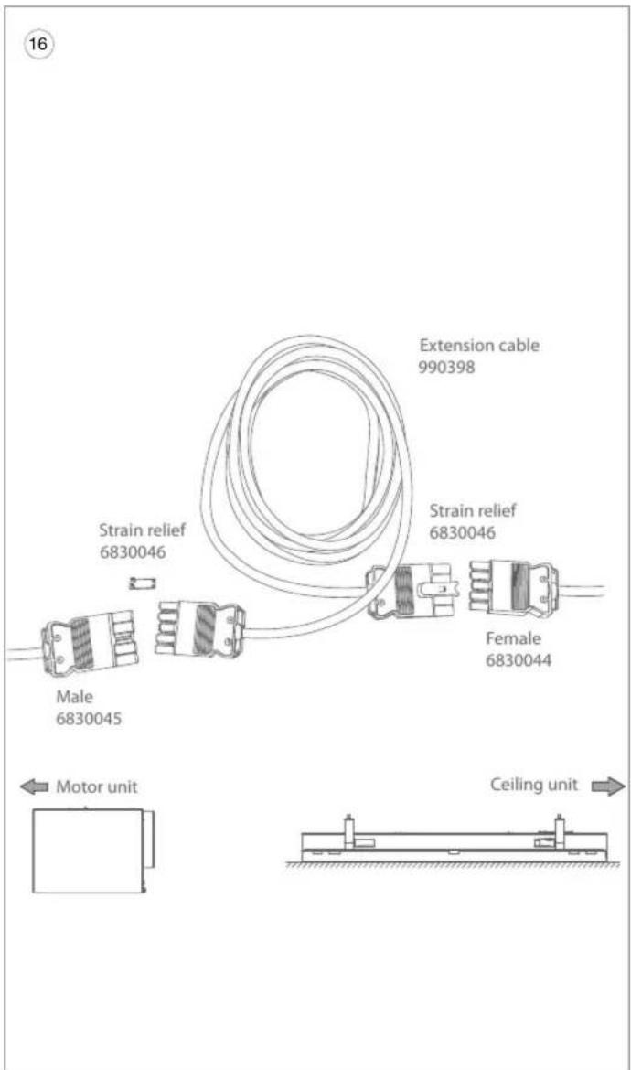
16 Extension cable 990398 Strain relief 6830046 Strain relief 6830046 Female 6830044 Male 6830045 Motor unit Ceiling unit16 Connect the supplied cable (990398) between the build-in unit and the motor unit using the connectors. The length of this cable is 5 m. Optional, you can order an extra extension cable (7000094), resulting in a total cable length of 10 m.
Mount the strain reliefs (6830046) on the two connector connections.
Place the grease filter and, if applicable, the recirculation filter in the cooker hood.
Check that the filters are fitted and locked properly. Close the bottom panel.
The power can now be restored and the cooker hood is ready for use.
NOVY nv reserves the right at any time and without reservation to change the structure and the prices of its products.
NOVY nv
Noordlaan 6
B - 8520 KUURNE
Tel. 0032 (0) 56/36.51.00
info@novy.com
www.novy.com