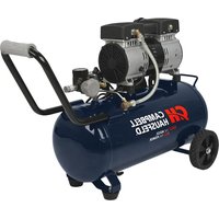
DC080500 - Compressor Campbell Hausfeld - Free user manual and instructions
Find the device manual for free DC080500 Campbell Hausfeld in PDF.


User questions about DC080500 Campbell Hausfeld
0 question about this device. Answer the ones you know or ask your own.
Ask a new question about this device
Download the instructions for your Compressor in PDF format for free! Find your manual DC080500 - Campbell Hausfeld and take your electronic device back in hand. On this page are published all the documents necessary for the use of your device. DC080500 by Campbell Hausfeld.
USER MANUAL DC080500 Campbell Hausfeld
CH CAMPBELL HAUSFELD
Operating Instructions and Parts Manual
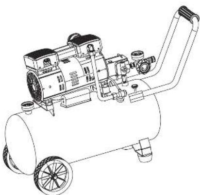
natural_image
Line drawing of an air compressor with wheels and control panel (no text or symbols)Model: DC080500
© 2016 Campbell Hausfeld
A MergerBerkshire Hathaway Company
EN
INE41800AV 5/16
CH CAMPBELL HAUSFELD.
Please read and save these instructions. Read carefully before attempting to assemble, install, operate or maintain the product described.
Protect yourself and others by observing all safety information. Failure to comply with instructions could result in personal injury and/or property damage! Retain instructions for future reference.
REMINDER: Keep your dated proof of purchase for warranty purposes! Attach it to this manual or file it for safekeeping.
Model #:
Serial #:
Purchase Date:
For parts, product & service information visit www.campbellhausfeld.com
Campbell Hausfeld 100 Production Drive Harrison, Ohio 45030
REGISTER YOUR PRODUCT ONLINE NOW! www.campbellhausfeld.com READ AND FOLLOW ALL INSTRUCTIONS • SAVE THESE INSTRUCTIONS • DO NOT DISCARD
text_image
Technical diagram of a mechanical assembly with labeled components and exploded viewsThank you for purchasing this Campbell Hausteld quiet, oilless compressor. For over 100 years, we have manufactures products that are durable, reliable and just easy to use and maintain. Portable oilless air compressors are for home and workshop use. Cleaning or replacement of the inlet filter on all models and draining moisture from the air receivers are required maintenance.
UNPACKING
⚠ CAUTION Do not lift or move unit without appropriately rated equipment. Be sure the unit is securely attached to lifting device used. Do not lift unit by holding onto tubes or coolers. Do not use unit to lift other attached equipment.
After unpacking the unit, inspect carefully for any damage that may have occurred during transit. Check for loose, missing or damaged parts. Check to be sure all supplied accessories are enclosed with the unit. In case of questions, damaged or missing parts, please visit www.campbellhausfeld.com for customer assistance. assistance.
WARNING unit if damaged during shipping, handling or use. Damage may result in bursting and cause injury or property damage.
GENERAL SAFETY INSTRUCTIONS
Overview of Safety Warning System and Your Responsibilities
READ THIS MANUAL BEFORE USING THIS PRODUCT. FAILURE TO FOLLOW THE INSTRUCTIONS AND SAFETY PRECAUTIONS IN THIS MANUAL CAN RESULT IN SERIOUS INJURY OR DEATH. KEEP THIS MANUAL FOR FUTURE REFERENCE.
Your safety and the safety of others depend on you thoroughly reading and understanding this manual. If you have questions or do not understand the information presented in this manual, please visit www.campbellhausfeld.com.
This is the safety alert symbol. It is used to alert you to potential personal injury hazards. The meaning of this safety alert symbol is as follows: Attention! Become Alert! Your Safety may be at Risk. The message that appears next to the warning which can be either written or pictorially presented. Operations that may cause product damage are identified by the signal word "NOTICE" in this manual.
Most tool-related incidents are caused by failure to observe basic safety rules or precautions. You must be alert to potential hazards. You must have the necessary training, skills and tools to perform these functions. Campbell Hausfeld cannot anticipate every possible circumstance that might involve a potential hazard. Therefore, the warnings in this manual are not all inclusive. If a tool, procedure, work method or operating technique that is not specifically recommended by Campbell Hausfeld is used, you must satisfy yourself that it is safe for you and for others. You should also ensure that the product will not be damaged or be made unsafe by the operation, lubrication, maintenance or repair procedures that you choose.
Safety Guidelines
This manual contains information that is very important to know and understand. This information is provided for SAFETY and to PREVENT EQUIPMENT PROBLEMS. To help recognize this information, observe the following symbols.
A DANGER imminently hazardous situation which, if not avoided, WILL result in death or serious injury.
WARNING potentially hazardous situation which, if not avoided, COULD result in death or serious injury.
CAUTION Caution indicates a potentially hazardous situation which, if not avoided, MAY result in minor or moderate injury.
NOTICE Notice indicates important information, that if not followed, may cause damage to equipment.
IMPORTANT or NOTE: Information that requires special attention.
GENERAL SAFETY INSTRUCTIONS (CONTINUED)
Safety Symbols
The following Safety Symbols appear throughout this manual to alert you to important safety hazards and precautions.

PAM
(4) 1935

Pink of

Wear Eye
and/Heaving
Proletativ

Aisk of

Rise of
So

Pick of
Koang Pcs

Risk of Stock

x'
Lipakov
California Proposition 65
This warning is power cord may contain chemicals known to the State of California to cause
cancer and birth defects or other reproductive harm. Wash hands after handling.
If you can just when you cut, sand, drill or grind materials such as wood, paint, metal,
- concrete, cement, or other machinery. This dust often contains chemicals known to cause cancer, birth defects, or other reproductive harm. Wear protective gear.
Important Safety Information
Please read and save these instructions. Read carefully before attempting to assemble, install, operate or maintain the product described. Protect yourself and others by observing all safety information. Failure to comply with instructions could result in personal injury and/or property damage! Retain instructions for future reference.
This manual contains important safety, operational and maintenance information. If you have any questions, please visit www.camebellhausfeld.com for customer assistance.
Since the air compressor and other components used (material pump, spray guns, filters, lubricators, hoses, etc.) make up a high pressure pumping system, the following safety precautions must be observed at all times:
-
Read all manuals included with this product carefully. Be thoroughly familiar with the controls and the proper use of the equipment.
-
Follow all local electrical and safety codes as well as in the United States, the National Electrical Codes (NEC) and Occupational Safety and Health Act (OSHA).
- Only persons well acquainted with these rules of safe operation should be allowed to use the compressor.
- Keep visitors away and keep out of reach of children.
- Wear safety glasses and use hearing protection when operating the unit
- Do not stand on or use the unit as a handhold.
- Before each use, inspect compressed air system and electrical components for signs of damage, deterioration, weakness or leakage. Repair or replace defective items before using.
- Check all fasteners at frequent intervals for proper tightness.
A WARNING Motors, electrical equipment and controls can cause electrical arcs that will ignite a flammable
gas or vapor. Never operate or repair in or near a flammable gas of vapor. Never store flammable liquids or gases in the vicinity of the compressor.
WARNING
WARNING: Do not operate with guard removed.
WARNING: Risk of electric shock. Use GFCL Use indoues only. Disconnect all connections before surviving.
text_image
Exploded diagram of an industrial machine with numbered components for identification- Do not wear loose clothing or jewelry that will get caught in the moving parts of the unit.
CAUTION Compressor parts may be hot even if the unit is stopped.
-
Keep fingers away from a running compressor; fast moving and hot parts will cause injury and/or burns.
-
If the equipment should start to vibrate abnormally, STOP the engine/motor and check immediately for the cause. Vibration is generally a warning of trouble.
-
To reduce fire hazard, keep engine/motor exterior free of oil, solvent, or excessive grease.
20 WARNING safety relief valve with a setting no higher than the maximum allowable working pressure (MAWP) MUST be installed in the tank for this compressor. The ASME safety valve must have sufficient flow and pressure ratings to protect the pressurized components from bursting.
CAUTION specification decal for maximum operating pressure. Do not operate with pressure switch or pilot valves set higher than the maximum operating pressure.
- Never attempt to adjust ASME safety valve. Keep safety valve free from paint and other accumulations.
WARNING NEVER use plastic (PVC, ABS, or CPVC) pipe for compressed air.
⚠️ DANGER Sturbing. If air tank develops a leak, replace the air tank immediately. Never repair, weld, or modify the air tank or attachments. Never make adjustments to the factory set pressures. Never exceed manufacturer's maximum allowable pressure rating of attachments.
NOTICE Drain liquid from tank daily.
-
Tanks rust from moisture build-up, which weakens the tank. Make sure to drain tank regularly and inspect periodically for unsafe conditions such as rust formation and corrosion.
-
Fast moving air will stir up dust and debris which may be harmful. Release air slowly when draining moisture or depressurizing the compressor system.
WARNING injury or death could occur from inhaling compressed air. Never inhale air from the air compressor either directly or from a breathing device connected to the air compressor. The air stream may contain carbon monoxide, toxic vapors or solid particles.
Do not spray flammable materials in vicinity of open flame or near ignition sources including the compressor unit.
Spraying Precautions
WARNING of fire and explosion. When a combustible liquid is sprayed there can be danger of fire or explosion, especially in a closed area. Keep the compressor/motor at least 6 meters (18 feet) away from explosive vapors.
-
DO NOT spray flammable materials in vicinity of open flame or near ignition sources including the compressor unit. Keep away from heat, sparks and flame.
-
DO NOT smoke. Extinguish all flames and pilot lights and turn off stoves, heaters, electric motors, and other sources of ignition during use and until all vapors are gone.
-
Prevent build-up of vapors by opening all windows and doors to achieve cross-ventilation. Use only with adequate ventilation.
-
Do not breathe dust, vapors, or spray mist. Ensure fresh air entry during application and drying. If you experience eye watering, headache or dizziness, wear respiratory protection (NIOSH approved or equivalent) or leave the area.
-
Follow OSHA and CSA safety regulations for personal protective equipment. Typical equipment may include safety glasses, respirator, and/or work gloves and is dependent upon the application type, amount of use and workspace.
SPECIFICATIONS
| DC080500 | |
| Motor HP 1.6 | |
| Tank Capacity & gallon | |
| Phase Single | |
| Number of Cylinders 2 | |
| Air Delivery @ 90 psi 2.4 SCFM | |
| Voltage 110 - 120 | |
| Amperes 7 | |
| Hertz (Cycle) 50 | |
| Maximum Pressure 125 psi | |
| RPM 1750 | |
| Tank Outlet Size 1/4 in. IM Quick Connect | |
| Unit Weight | 61.94 pounds |
DIMENSIONS
| DC080500 | |
| Length | 33.85 in. |
| Width | 13.39 in. |
| Height 22.83 in. |
NOTAS
Sp13
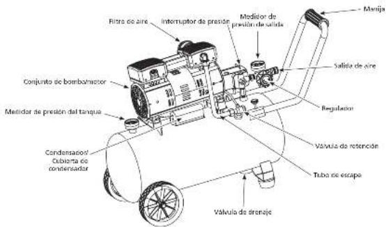
GETTING TO KNOW YOUR COMPRESSOR
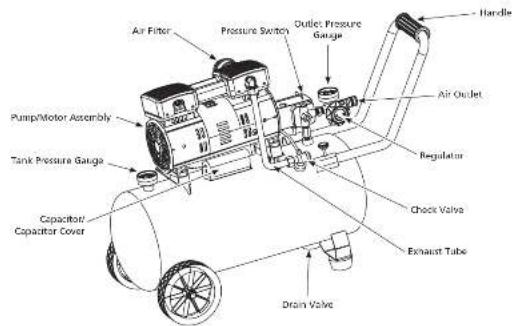
text_image
Air Filter Pressure Switch Outlet Pressure Gauge Pump/Motor Assembly Tank Pressure Gauge Capacitor/ Capacitor Cover Drain Valve Handle Air Outlet Regulator Check Valve Exhaust TubePSI (Pounds per Square Inch) - Measurement of the pressure exerted by the force of the air. The actual psi output is measured by a pressure gauge on the compressor.
SCFM (Standard Cubic Feet per Minute) - Sometimes called CFM (Cubic Feet per Minute). Measurement of air volume delivered by the compressor.
Air Delivery - A combination of psi and SCFM. The air delivery required by a tool is stated as (number) SCFM at (number) psi. The combination of these figures determines what size unit is needed.
Air Tank Capacity - The volume of air stored in the tank and available for immediate use. A large tank allows the intermittent use of an air tool with an air requirement higher than the compressor's rated delivery.
Amps or Amperage - A measure of the electrical force minus the resistance on an electrical line. This air compressor requires 15 amps for operation. Be sure the compressor will operate on an electrical line with the proper amps. If other appliances operate on the same line, they will reduce the available amps. If the amperage is not adequate, the result will be blown fuses or tripped circuits.
Volts or Voltage - A measurement of the force of an electrical current.
Cut-in/Cut-off Pressure - Specific psi at which a compressor starts and stops while refilling the air tank.
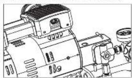
Pressure Switch - Auto On/Off Switch - In the "Auto On" position, the compressor shuts off automatically when tank pressure reaches the maximum preset pressure. After air is used from the tank and drops to a preset low level, the pressure switch automatically turns the motor back on. In the "Off" position, the compressor will not operate. This switch should be in the "Off" position when connecting or disconnecting the power cord from the electrical outlet. (Figure 2)
When the pressure switch turns the motor off you will hear air leaking out of the pressure switch unloader valve for a short time. This releases the air pressure from the discharge tube and allows the compressor to restart easier.
natural_image
Technical line drawing of a mechanical device with no visible text or symbolsFigure 2
GETTING TO KNOW YOUR COMPRESSOR (CONTINUED)
Regulator - The regulator controls the amount of air pressure at the hose outlet. Turning regulator knob clockwise (to the right) will increase air pressure at the outlet. Turning knob counterclockwise (to the left) will lower air pressure to the outlet. Turning knob fully counterclockwise will shut off flow of air completely.
Handle - Designed to move the compressor.
ASME Safety Valve - This valve automatically releases air if the tank pressure exceeds the preset maximum.
Exhaust Tube - This tube carries compressed air from the pump to the check valve. This tube becomes very hot during use. To avoid the risk of severe burns, never touch the exhaust tube.
Check Valve - One-way valve that allows air to enter the tank, but prevents air in the tank from flowing back into the compressor pump.
Air Outlet - A quick connect coupler designed to work in combination with a quick connect plug to quickly and easily join the compressor to an air hose.
Pressure Gauges - These gauges will show air pressure in the compressor tank and at the compressor outlet.
Outlet Pressure Gauge - Will show air pressure at the outlet in pounds per square inch (psi). Make sure this gauge reads ZERO (by adjusting regulator knob fully counterclockwise) before changing air tools or disconnecting air hose from outlet.
Tank Pressure Gauge - Will show air pressure in tank while the compressor is running, indicating compressor is building pressure properly. This gauge will show maximum pressure of compressor when it shuts off automatically at the pressure switch.
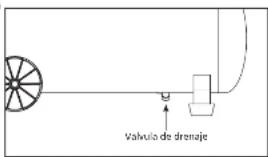
Drain Valve - This valve is located underneath the tank. Use this valve to drain moisture from the tank daily to reduce the risk of corrosion.
CAUTION
Drain liquid from tank daily.
Reduce tank pressure below 10 psi, then drain moisture from tank daily to avoid tank corrosion. Drain moisture from tank by opening the drain valve located underneath the tank.
MOTOR SPECIFICATIONS AND ELECTRICAL REQUIREMENTS
Power Supply and Motor Specifications
NOTICE
Electrical hazards, fire hazards or damage to the tool, use proper circuit protection.
NOTICE
Your tool is wired at the factory for operation using the voltage shown. Connect tool to a power line with the appropriate voltage and a 15-amp branch circuit. Use a 15-amp time delay
0347125457
It shock or fire, if power cord is worn or cut, or damaged in any way, have it replaced immediately.
The A-C motor used on this compressor is a permanent split capacitor non-reversible induction type, having the following specifications. It is wired at the factory for operation on 110V-120V AC, 60 Hz service.
MOTOR SPECIFICATIONS
| Voltage 110 - 120 |
| Ampereus 7 |
| Hertz (Cycles) 60 |
| Phase Single |
| RPM 1750 |
Limpieza
natural_image
Line drawing of a hand holding a small object, possibly a tool or device (no text or symbols present)Figura 4
General Electrical Connections

WARNING: 1. Use electric shock. Use GFCI. Use indoors only. Disconnect all connections before servicing. Use identical replacement parts. Servicing must be performed by a licensed, qualified electrician.
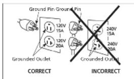
In the event of a malfunction or breakdown, grounding provides a path of least resistance for electrical current to reduce the risk of electric shock. This compressor is equipped with an electric cord having an equipment-grounding conductor and a grounding plug, as shown. The plug must be plugged into a matching outlet that is properly installed and grounded in accordance with all local codes and ordinances.
Improper connection of the equipment-grounding conductor can result in a risk of electric shock. The conductor with insulation having an outer surface that is green with or without yellow stripes is the equipment-grounding conductor. If repair or replacement of the electric cord or plug is necessary, do not connect the equipment-grounding conductor to a live terminal.
If the grounding instructions are not completely understood, or if you are in doubt as to whether the compressor is properly grounded check with a qualified electrician or service personnel.
Grounding Instructions
- This product is for use on a nominal 120 v circuit. It must be grounded. In the event of an electric short circuit, grounding reduces the risk of electrical shock by providing an escape wire for the electric current. Unit is equipped with a cord that has a grounding prong. It will fit one of the common outlet types shown in Figure 3. If plug will not fit in the desired outlet, have the plug or the outlet replaced by a qualified electrician.
WARNING: Info of electric shock.
Improper use of grounding plug can result in a risk of electrical shock. Plug must be plugged into an outlet that is properly installed and grounded in accordance with local codes and ordinances
text_image
Ground Pin Ground Pin 120V 15A 120V 20A Grounded Outlet CORRECT 240V 15A 240V 20A Grounded Outlet INCORRECTFigure 3 - Grounding Method
NOTICE
NOTICE: Do not use grounding adapter.
- Always check with a qualified electrician or serviceman if the grounding instructions are not completely understood, or if in doubt as to whether the product is properly grounded. Do not modify the plug provided; if it will not fit the outlet, have the proper outlet installed by a qualified electrician.
- Use only a 3-wire extension cord that has a 3-blade grounding plug, and a 3-slot receptacle that accepts the plug on the product. Make sure your extension cord is not damaged. When using an extension cord, be sure to use one heavy enough to carry the current your product draws. For lengths less than 25ft. 16-3 AWG extension cords shall be used. An undersized cord results in a drop in the voltage and loss of power and overheating. (NOTICE: Table 1 shows the correct size to use depending on cord length. When in doubt, use the next heavier gauge. The smaller the gauge number, the heavier the cord.)
- Use of an extension cord may cause excess heat to motor. This could lead to tripped breaker (at electrical panel) or tripped thermal overload (on compressor motor). If this occurs, eliminate extension cord and plug compressor directly into electrical outlet. Avoid using extension cords; use longer air hose(s) instead.
If repair or replacement of the cord or plug is necessary, do not connect the grounding wire to either flat blade terminal. The wire with insulation having an outer surface that is green with or without yellow stripes is the grounding wire.
MOTOR SPECIFICATIONS AND ELECTRICAL REQUIREMENTS (CONTINUED)
Extension Cords
-
The air compressor should be located where it can be directly plugged into an outlet. Although extension cord is not recommended, if you must use only a 3 wire extension cord that has a 3 blade grounding plug and a 3 slot receptacle that accepts the plug on the product. When using an extension cord be sure to use one heavy enough to carry the current the product draws.
-
To avoid loss of power and overheating, additional air hose must be used to reach work area instead of extension cords.
| AMP RATING RANGE | VOLTAGE CORD LENGTH IN FEET | |||||||||
| 120V 25 | ft 50 ft 100 | ft 150 ft 200 | ft 250 ft 300 | ft 400 ft 500 | ft | |||||
| 12-14 16 12 10 | 0 8 6 4 4 2 | |||||||||
110-120 volt, 60Hz Information
The plug supplied on your compressor may not fit into the outlet you are planning to use. Your local electrical code may require slightly different power cord plug connections. If these differences exist refer to and make the proper adjustments per your local code before your compressor is plugged in and turned on.
Plugs and Receptacles
-
If the plug on the electrical cord of the unit is unfamiliar to you or will not fit your particular receptacle, Figure 2 will help you understand why by illustrating the different plugs and the voltages they are to be used with.
-
Make sure that the product is connected to an outlet having the same configuration as the plug.
-
The receptacles must be connected to circuits rated to carry at least the voltage and amperages shown.
-
NEVER have a receptacle replaced with one of a higher amperage before determining the change can be made according to all electrical codes affecting your particular area. The installation should be made by a qualified electrician. If the products must be reconnected for use on different types of circuits, the reconnection should be made by qualified personnel.
WARNING Overheating, short circuiting and fire damage will result from inadequate wiring.
Electrical Installation
⚠ WARNING All wiring and electrical connections should be performed by a qualified electrician. Installation must be in accordance with local codes and national electrical codes.
Wiring
-
Local electrical wiring codes differ from area to area. Source wiring, plug and protector must be rated for at least the amperage and voltage indicated on motor nameplate, and meet all electrical codes for this minimum.
-
Use a slow blow fuse or a circuit breaker.
-
This product is for use on a nominal 120 volt circuit and has a grounding plug that looks like the plug illustrated in Figure 3.
Make sure the product is connected to an outlet having the same configuration as the plug. This product must be grounded. In the event of an electrical short circuit, grounding reduces risk of electrical shock by providing an escape wire for electric current. This product is equipped with a cord having a grounding wire with an appropriate grounding plug. Plug must be plugged into an outlet that is properly installed and grounded in accordance with all local codes and ordinances.
CAUTION Overheating, short circuiting and fire damage will result from inadequate wiring.
Do not modify the plug provided. If it will not fit the outlet, have the proper outlet installed by a qualified electrician.
⚠️ CAUTION If not properly grounded, this tool can cause an electrical shock, particularly when used in damp locations, in proximity of plumbing, outdoors.
▲ DANGER Do not use a grounding adapter with this product!
⚠ WARNING All wiring and electrical connections should be performed by a qualified electrician. Installation must be in accordance with local codes and rational electrical codes.
⚠ WARNING Improper installation of grounding plug is able to result in a risk of electric shock. When repair or replacement of the cord or plug is required, do not connect the grounding wire to either flat blade terminal. The wire with insulation having an outer surface that is green with or without yellow stripes is the grounding wire.
⚠ WARNING Never connect green (or green and yellow) wire to a live terminal.
CAUTION Overheating, short circuiting and fire damage will result from inadequate wiring, etc.
Thermal Overload Protector
This compressor has an automatic thermal protector that shuts off the motor if it overheats or has too much current. This protector is a "trip and hold" protector. To reset, unplug the compressor and allow it to completely cool. This should allow the automatic overload to reset. The protector may not reset unless it is unplugged.
The motor must be allowed to cool down before start-up is possible. The motor may automatically restart without warning if left plugged into the electrical outlet, and the motor is turned on.
INSTALLATION
- Check and tighten all bolts, fittings, etc., before operating compressor.
- Operate compressor in a ventilated area so that compressor may be properly cooled.
- Compressor should be located where it can be directly plugged into an outlet. Do not use extension cords with this unit.
- To avoid loss of power and overheating, it is better to use additional air hose instead of extension cords to reach work area.
OPERATION
Before first start-up
Break-in procedure
Complete this procedure before using compressor for the first time. Once completed, it is not necessary to repeat.
- Turn ON/OFF switch to OFF position.
- Open the tank drain valve.
- Plug in power cord.
- Turn ON/OFF switch to ON position and run compressor for 30 minutes.
- Turn ON/OFF switch to OFF position.
- Unplug power cord.
- Close drain valve
The compressor is now ready for use.
OPERATION (CONTINUED)
Before Each Start-up
Operating Procedure
-
Turn regulator knob fully counter clockwise (to the left) to close air flow.
-
Connect air hose to outlet of regulator
-
Turn ON/OFF Switch to OFF position.
-
Plug in power cord.
-
Turn ON/OFF Switch to ON position and let compressor run until it reaches automatic shutoff pressure.
-
Attach tire chuck or tool to end of hose.
-
Adjust regulator to proper pressure for tool or tire. Operate tool per instructions.
As air is depleted from the tank by use of a tire chuck, tool, etc., the compressor will restart automatically
at its preset "cut-in" pressure. When a tool is being used continuously, the compressor will cycle on and off
automatically.
- Turn switch to OFF position, unplug power cord and drain tank.
MAINTENANCE
WARNING
Disconnect power source then release all pressure from the system before attempting to install,
service, Redicate or perform any maintenance. Service should be performed by an authorized
The compressors should be checked often for no visible problems and the following maintenance
procedures should be performed each time the compressor is used.

ASME Safety Valve
WARNING
WARNING: Wear safety gloves. Check the safety value by performing the following steps:
-
Turn the air compressor on and allow the tank to fill. The compressor will shut off when the pressure reaches the preset maximum.
-
Turn the air compressor off.
-
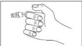
Pull the ring on the safety valve to release the air for several seconds. ALWAYS use your hand to deflect fast moving air past your face.
-
Release the ring. Air will stop escaping when the
ring is released at approximately 40 psi - 60 psi.
- If air leaks after the ring has been released, or if the valve is stuck and cannot be actuated by the ring, remove the unit from service. DO NOT use
the air compressor until the safety valve has been replaced. Use of the air compressor in this condition
could result in death of serious obesity injury.
natural_image
Line drawing of a hand holding a small object (no text or symbols)Figure 4

WARNING
Safety valve must be replaced if it cannot be actuated or it leaks air after ring is released.
Drain Tank
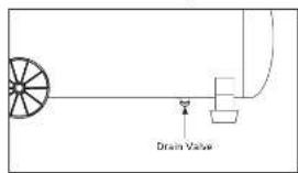
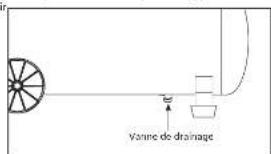
With compressor shut off and pressure released: Drain moisture from tanks by opening drain valve underneath tanks (See Figure 5).
text_image
Drain ValveFigure 5
Turn power OFF and clean dust and dirt from motor, tank, air lines and pump cooling fins.
IMPORTANT: Unit should be located as far from spraying area as hose will allow to prevent over-spray from clogging air filter.
Air Filter
Check air filter to be sure it is clean. To service a filter, remove the filter housing cover. Remove filter and clean foam or filter in hot, soapy water (Paper filters cannot be washed). Rinse and let dry. Replace air filters that cannot be cleaned. Place filter back in the housing base. Replace cover.
Lubrication
This is an oilless type compressor requiring no lubrication.
End of Operation/Storage
-
Turn Auto ON/OFF switch to OFF position.
-
Unplug power cord from wall outlet and wrap around handle to prevent damage when not in use.
-
Wearing safety glasses drain tank of air by pulling the ring on the safety valve. Use other hand to deflect fast moving air from being directed toward your face.
-
Drain tank of condensation by opening drain valve on bottom of tank. Tank pressure should be below 10 psi when draining tank.
-
Air hose should be disconnected from compressor and open end hanging down to drain condensation.
- Compressor and hose should be stored in a cool, dry place.
Technical Service
For information regarding the operation or repair of this product, please call 1-000-543-6400.
| MAINTENANCE SCHEDULE | ||
| Operation | Daily | Weekly |
| Drain Tank | ● | |
| Check Air Filter | ● | |
| Check Safety Valve | ● | |
| Blow Dirt from Inside Motor | ● | |
TROUBLESHOOTING GUIDE
SYMPTOM POSSIBLE CAUSE(S) CORRECTIVE ACTION
| Compressor will not run 1. Unit is plugged into extension core 1. Remove extension core or use larger gauge |
| extension cord | |
| 2. No electrical power 2. Turn on pressure switch? Plugged in? Check user breaker or motor overload | |
-
Blown fuse 5. Replace blown fuse
-
Breaker open 4. Robot, determining why problem happened
-
Thermal overload open 5. Unplug sent allow motor to coal before trying to
-
Pressure switch defective 6. Replace
-
Shouted at press motor winding 7. Replace value
-
2017年 ,公司及子公司
Motor hairs but cannot run or runs slowly
(No text)
Fuse block/circuit breaker trips repeatedly
-
Low voltage=1. Check with volume
-
Unit is plugged into extension cord 2. Remove extension cord or use larger gauge
-
Shorted or open motor winding 3. Replace motor
-
Defecation: black value on unloading; Surplants on repair
-
Intersect size fuse, circuit overlanched 1. Check for proper fuse, use time-delay fuse.
Disconnect other electrical appliances from circuit or
- Unit is plugged into extension cord 2. Remove extension cord or use larger gauge
extension cord
- Defective check valve or unloader 3. Replace or repair
Thermal overload protection cuts out repeatedly
Thermal overload protection 1. Low voltage 1. Check with voltmeter
cuts out repeatedly 2. Clogged air filter
- Lack of proper ventilation/room
temperature too high
- Unit is plugged into extension cord 4.
HOLDEN-DRD
- Loose connections fittings, tubing, 1. Check all connections with soap and water solution
[Unreadable]
-
Loose drain value
-
Check valve locking
-
Checks tanks for cracks or pin holes
Excessive moisture in
discharge air
Air output lower than unirral
(1) 本次股东大会的召集和召开程序
[Non-Text]
-
Broken inlet valves
-
Intake filter dirty
-
Connections leaking
-
Clean filter (see Maintenance section)
-
Move compressor to well ventilated area
- Check all connections with soap and water solution
and tighten
-
Tighter
-
Disassemble check valve assembly, clean or replace
A DANGER Do not disassemble check valve
with air in tank: blood tank first
- Check all connections with soap and water
Tighton
-
How much will we see something like what was
-
2017年公司实现的利润为人民币1,356,849.44元。
-
2018年1月1日
-
Tighten connections
CONOZCA SU COMPRESOR
natural_image
Line drawing of a mechanical device with gears and a fan (no text or symbols)Figure 2
ESPECIFICACIONES
text_image
Exploded diagram of an industrial machine with numbered components for identificationFor Repair Parts, visit www.campbellhausfeld.com 24 hours a day - 365 days a year
Please provide following information:
Model number Serial number (if any)
Part description and number as shown in parts list

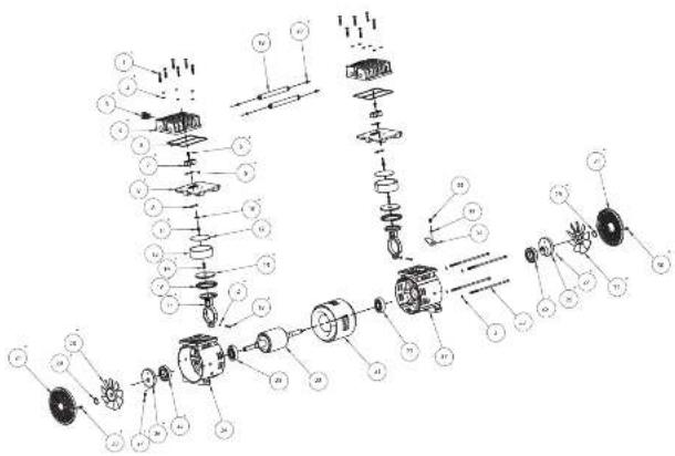
REPAIR PARTS ILLUSTRATION FOR SR060510SV

text_image
Technical diagram of a mechanical assembly with labeled components and exploded viewsFor Repair Parts, visit www.campbellhausfeld.com
24 hours a day - 365 days a year
Please provide following information:
Model number Serial number (if any)
Part description and number as shown in parts list
ANTES DE COMENZAR
Descripción
CH CAMPBELL HAUSFELD.
Harrison, Ohio 45030
¡REGISTRE SU PRODUCTO EN LÍNEA AHORA MISMO! www.campbellhausfeld.com LEA Y SIGA TODAS LAS INSTRUCCIONES • GUARDE ESTAS INSTRUCCIONES • NO LAS DESECHE
REPAIR PARTS LIST FOR SR060510SV
| Ref.No. | Description Part Number: Qty. | |
| 1 | BOLT, M5 X 30 | ● 12 |
| 2 | SPRING WASHER, M5 | ● ▲ 18 |
| 3 | REFLIFE VALVE | ▶ 1 |
| 4 | CYLINDER HEAD | ● 2 |
| 5 | SEAL OF CYLINDER HEAD 2 | |
| 6 | SCREW, M4 X 8 | ■ 2 |
| 7 | VALVE LIFT GLARD | ■ 2 |
| 8 | VALVE REED | ■ 4 |
| 9 | VALVE PLATE | ■ 2 |
| 10 | VALVE BACKER | ■ 2 |
| 11 | SCREW, M4 X 5 | ■ 2 |
| 12 | O RING OF CYLINDER 2 | |
| 13 | CYLINDER -2 | |
| 14 | PISTON CAP SCREW | ▲ 2 |
| 15 | PISTON CAP | ▲ 2 |
| 16 | PISTON RING | ▲ 2 |
| 17 | CON-ROD | ▲ 2 |
| 18 | CON-ROD SCREW, M5 X 26 | ▲ 2 |
| 19 | CROSSOVER TUBE | ▼ 2 |
| 20 | O-RING FOR CROSSOVER TUBE | ▼ 4 |
| 21 | STATOR -1 | |
| 22 | ROTOR -1 | |
| 23 | BEARING 2 | |
| 24 | FRONT END BELL -1 | |
| 25 | BEARING | ◆ 2 |
| 26 | ECCENTRIC | ◆ 2 |
| 27 | ECCENTRIC SCREW, M5 X 10 | ◆ 2 |
| 28 | COOLING FAN LEFT | ○ 1 |
| 29 | EXTERNAL RETAINING RING | ○ □ 2 |
| 30 | TAMPING SCREW, STR X 16 | ○ □ 4 |
| 31 | COOLING FAN COVER | ○ □ 2 |
| 32 | COOLING FAN RIGHT | □ 1 |
| 33 | MOTOR BOLT, M5 X 182 -4 | |
| 34 | SCREW, M4 X 6 -1 | |
| 35 | WASHER, M4 -1 | |
| 36 | GROUND SIGNAL -1 | |
| 37 | REAR END BELL -1 | |
REPAIR PARTS KITS
| ● | PUMP HEAD KIT | SR0605135V |
| ■ | VALVE PLATE KIT | SR0605205V |
| ▲ | PISTON CYLINDER KIT | SR0605215V |
| ▼ | CROSSOVER TUBE HITTING KIT | SR0605225V |
| ◆ | ECCENTRIC/BEARING ASSEMBLY KIT | SR0605235V |
| ○ | FRONT END FAN KIT | SR3605245V |
| □ | MOTOR FAN KIT | SR3605255V |
| ▶ | COLD START VALVE KIT | SR3605265V |
CH CAMPBELL HAUSFELD
Reminder: Keep your dated proof of purchase for warranty purposes! Attach it to this manual or file it for safekeeping.
LIMITED WARRANTY
- DURATION: From the date of purchase by the original purchaser as follows: One Year.
-
WHO GIVES THIS WARRANTY (WARRANTOR): Campbell Hausfeld a Marmon/Barkshire Hathaway Company, 100 Production Drive, Harrison, Ohio, 45030, Visit www.campbellhausfeld.com
-
WHO RECEIVES THIS WARRANTY (PURCHASER): The original purchaser (other than for purposes of resale) of the Campbell Hausfeld compressor.
-
WHAT PRODUCTS ARE COVERED BY THIS WARRANTY: This DC080500 Campbell Hausteld air compressor.
-
WHAT IS COVERED UNDER THIS WARRANTY: Parts and Labor to remedy substantial defects due to material and workmanship during the first year of ownership with the exceptions noted below. Parts only to remedy substantial defects due to material and workmanship during remaining term of coverage with exceptions noted below.
-
WHAT IS NOT COVERED UNDER THIS WARRANTY:
A. Implied warranties, including those of merchantability and FITNESS FOR A PARTICULAR PURPOSE ARE LIMITED FROM THE DATE OF ORIGINAL PURCHASE AS STATED IN THE DURATION. If the compressor is used for commercial, industrial or rental purposes, the warranty will apply for ninety (90) days from the date of purchase. Two-stage compressors are not limited to a ninety (90) day warranty when used in commercial or industrial applications. Some States do not allow limitations on how long an implied warranty lasts, so the above limitations may not apply to you
B. ANY INDICENTAL, INDIRECT, OR CONSEQUENTIAL LOSS, DAMAGE, OR EXPENSE THAT MAY RESULT FROM ANY DEFECT, FAILURE, OR MALFUNCTION OF THE CAMPBELL HAUSFELD PRODUCT. Some States do not allow the exclusion or limitations of incidental or consequential damages, so the above limitation or exclusion may not apply to you.
C. Any failure that results from an accident, purchaser's abuse, neglect or failure to operate products in accordance with instructions provided in the owner's manualist supplied with compressor.
D. Pre-delivery service, e.g., assembly, oil or lubricants, and adjustment.
E. Items or service that is normally required to maintain the product, e.g. lubricants, filters and gaskets, etc. F. Gasoline engines and components are expressly excluded from coverage under this limited warranty. The Purchaser must comply with the warranty given by the engine manufacturer which is supplied with the product.
G. Additional items not covered under this warranty;
- Excluded items pertaining to All Congressors a. Any component damaged in shipment or any failure caused by installing or operating unit under conditions not in accordance with installation and operation guidelines or damaged by contact with tools or surroundings.
b. Pump or valve failure caused by rain, excessive humidity, excessive environments or other contaminants.
C. Cosmetic defects that do not interfere with compressor functionality.
b. Rusted banks, including but not limited to last due to improper drainage of corrosive environments.
b. The following components are considered minimal wear items and are not covered after the first year of ownership. Electric motor, check valve, pressure switch, regulator, pressure gauges, hose, tubing, pipe, fittings and couplers, screws, nuts, hardware items, belts, pulleys, flywheel, air filter and housing, gauges, seals, oil leaks, air leases, oil consumption or usage, piston rings.
- Tank drain valves.
g. Damage due to incorrect voltage or improper wiring.
h. Other items not listed but considered general wear parts.
- Pressure switches, air governors, load/unload devices, throttle control devices and safety valves modified from factory settings.
i. Damage from inadequate filter maintenance.
k. Induction motors operated with electricity produced by a generator.
- Excluded items specific to Lubricated Compressors:
a. Pump wear or valve damage caused by using oil not specified.
b. Pump west or damage caused by any oil mediumation.
c. Pump wear or damage caused by failure to follow proper oil maintenance guidelines, operation below proper oil level or operation without oil.
H. Labor, service call, or transportation charges after the first year of ownership.
-
RESPONSIBILITIES OF WARRANTOR UNDER THIS WARRANTY: Repair or replace, at Warrantor's option, compressor or component which is defective, his malfunctioned and/or failed to conform within the duration of the specific warranty period.
-
RESPONSIBILITIES OF PURCHASER UNDER THIS WARRANTY:
A. Provide dated proof of purchase and maintenance records.
B. Call Campbell Household (800 543 6400) to obtain your warranty service options. Freight costs must be borne by the purchaser.
C. Use reasonable care in the operation and maintenance of the products as described in the owner's manual(s).
D. Repairs requiring overtime, weekend rates, or anything beyond the standard manufacturer warranty repair labor reimbursement rate.
E. Time required for any security checks, safety training, or similar for service personnel to gain access to facility.
- WHEN WARRANTY WILL PERFORM REPAIR OR REPLACEMENT UNDER THIS WARRANTY: Repair or replacement will be scheduled and
serviced according to the normal work flow at the servicing location, and depending on the availability of replacement parts. This Limited Warranty applies in the U.S., Canada and Mexico only and gives you specific legal rights. You may also have other rights which carry from State to State or country to country.
CH CAMPBELL HAUSFELD
natural_image
Line drawing of a portable air compressor with wheels and control panel (no text or symbols)Modelo: DC080500
© 2016 Campbell Hausfold A Memor/Berkshire Hackaway Company
SP
INE41800AV 5/16
CH CAMPBELL HAUSFELD
CH CAMPBELL HAUSFELD
natural_image
Line drawing of a portable air compressor with wheels and control panel (no text or symbols)Modèle: DC080500
© 2016 Campbell Hausfeld
A MergerBerkshire Hathaway Company
FR
INE41800AV 5/16
CH CAMPBELL HAUSFELD.
Harrison, Ohio 45030
ENREGISTREZ VOTRE PRODUIT EN LIGNE MAINTENANT ! www.campbellhausfeld.com LIRE ET SUIVRE TOUTES LES INSTRUCTIONS • CONSERVER CES INSTRUCTIONS • NE PAS JETER
ILLUSTRATION DES PIÈCES DE RÉPARATION POUR LE SR060510SV
| N° de réf. Description | Numéro de pièce : Qta | ||
| 1 BOULON, MS X 30 | ● | 12 | |
| 2 RONDILLE CLASSTIQUE, MS | ● ▲ | 18 | |
| 3 SOUFAPE DE DÉCHARGE | ▶ | 1 | |
| 4 CULASSE DE CYLINDRE | ● | 2 | |
| 5 JOINT DE LA CULASSE DE CYLINDRE -- 2 | |||
| 6 VIS, M4 X 8 | ■ | 2 | |
| 7 PROTECTION DE LA LEYLE DE SOUFAPE | ■ | 2 | |
| 8 CLAPET | ■ | 4 | |
| 9 PLAQUE PORTE-SOUPAPE | ■ | 2 | |
| 10 PIECE D'APPUI DE LA SOUPAPE | ■ | 2 | |
| 11 VIS, M4 X 6 | ■ | 2 | |
| 12 JOINT TORIQUE DU CYLINDRE | - 2 | ||
| 13 CYLINDRE | - 2 | ||
| 14 CAPUCHON VIS DU PISTON | ▲ | 2 | |
| 15 CHAPEAU DE LA BIELLE DU PISTON | ▲ | 2 | |
| 16 SEGMENT DE PISTON | ▲ | 2 | |
| 17 BIELLE | ▲ | 2 | |
| 18 VIS DE LA BIELLE, MS X 30 | ▲ | 2 | |
| 19 TUYAU DE RACCORDEMENT | ▼ | 2 | |
| 20 JOINT TORIQUE DU TUYAU DE RACCORDEMENT | ▼ | 4 | |
| 21 STATOR | 1 | ||
| 22 ROTOR | - 1 | ||
| 23 ROULEMENT | - 2 | ||
| 24 FLASQUE AVANT | - 1 | ||
| 25 ROULEMENT | 2 | ||
| 26 EXCENTROQUE | 2 | ||
| 27 VIS EXCENTREE, MS X 10 | 2 | ||
| 28 VENTILATUR DE REFROIDISSEMENT (KAUCHE) | ○ | 1 | |
| 29 BAGUE DE RETENUE EXTERNE | ○ □ | 2 | |
| 30 VIS DE SECURITE, STA X 18 | ○ □ | 4 | |
| 31 COUVERCLE DU VENTILATEUR DE REFROIDISSEMENT | ○ □ | 2 | |
| 32 VENTILATUR DE REFROIDISSEMENT (EXCRITE) | □ | 1 | |
| 33 BOULON DE MOTEUR, MS X 182 | - 4 | ||
| 34 VIS, M4 X 6 | - 1 | ||
| 35 RONDILLE, M4 | - 1 | ||
| 36 SIGNAL DE MISE À LA TERRE | 1 | ||
| 37 FLASQUE ARRIERE | 1 | ||
| TROUSSÉS DE PIÈCES DE RÉPARATION | |||
| ● | ENSEMBLE DE LA DE TETE DE POMPE | SR0605195V | |
| ■ | ENSEMBLE DE LA PLAQUE FORTE-SOUFAPE | SR0605205V | |
| ▲ | ENSEMBLE DU TUBE DU PISTON | SR0005215V | |
| ▼ | ENSEMBLE DU RACCORD DU TUYAU DE RACCORDEMENT | SR0005225V | |
| ◆ | ENSEMBLE DE L'ASSEMBLAGE EXCENTRIQUIDPADER | SR0005235V | |
| ○ | ENSEMBLE DU VENTILATEUR DE L'EXTREMITE AVANT | SR0605245V | |
| Q | ENSEMBLE DU VENTILATEUR DU MOTUR | SR0605255V | |
| > | ENSEMBLE DE LA SOUFAPE DE DEMARRAGE À PROD. | SR0605265V | |
NON OFFERT
ILLUSTRATION DES PIÈCES DE REMPLACEMENT POUR LE SR060510SV
text_image
Technical diagram of a mechanical assembly with labeled components and exploded viewsThe image is too blurry to recognize any text content.
text_image
Exploded view diagram of an industrial machine with numbered components for identificationnatural_image
Line drawing of a hand holding a small object (no text or symbols)Figure 4
text_image
vanne de drainageFigure 5


