MTC53-5BP - Multitools SCHEPPACH - Free user manual and instructions
Find the device manual for free MTC53-5BP SCHEPPACH in PDF.

| Product Type | 5-in-1 multi-function tool (trimmer, brush cutter, hedge trimmer, chainsaw, leaf blower) |
| Brand | Scheppach |
| Model | MTC53-5BP |
| Engine | 2-stroke engine, air-cooled |
| Displacement | 51.7 cm³ |
| Engine Power | 1.3 kW |
| Fuel Tank Capacity | 960 ml |
| Cutting Oil Tank Capacity (chainsaw) | 125 ml |
| Cutting Diameter (trimmer) | 450 mm |
| Cutting Diameter (brush cutter) | 255 mm |
| Cutting Length (hedge trimmer) | 400 mm |
| Cutting Length (chainsaw) | 254 mm |
| Max. Air Speed (blower) | 270 km/h |
| Weight (trimmer) | 12.0 kg |
| Weight (brush cutter) | 11.9 kg |
| Weight (hedge trimmer) | 12.5 kg |
| Weight (chainsaw) | 13.2 kg |
| Weight (with blower) | 12.6 kg |
| Sound Pressure Level | 97.3 dB(A) (K=3 dB) |
| Guaranteed Sound Power Level | 115.2 dB(A) |
| Vibrations (trimmer) | Front: 6.67 m/s², Rear: 5.67 m/s² (K=1.5 m/s²) |
| Vibrations (brush cutter) | Front: 6.96 m/s², Rear: 7.14 m/s² (K=1.5 m/s²) |
| Vibrations (hedge trimmer) | Front: 6.62 m/s², Rear: 6.62 m/s² (K=1.5 m/s²) |
| Vibrations (chainsaw) | Front: 6.62 m/s², Rear: 3.99 m/s² (K=1.5 m/s²) |
| Vibrations (blower) | Front: 7.37 m/s², Rear: 6.95 m/s² (K=1.5 m/s²) |
| Idle Speed | 3000 ±200 min⁻¹ |
Frequently Asked Questions - MTC53-5BP SCHEPPACH
User questions about MTC53-5BP SCHEPPACH
0 question about this device. Answer the ones you know or ask your own.
Ask a new question about this device
Download the instructions for your Multitools in PDF format for free! Find your manual MTC53-5BP - SCHEPPACH and take your electronic device back in hand. On this page are published all the documents necessary for the use of your device. MTC53-5BP by SCHEPPACH.
USER MANUAL MTC53-5BP SCHEPPACH
natural_image
Product photo of a Scheppach electric shaver tool with multiple blades and a power adapter (no text or symbols visible on main components)MTC53-5BP
| D | Benzin Multifunktionsgerät BackpackOriginal-Anleitung |
| GB | Petrol multi garden tool BackpackTranslation from the original instruction manual |
| FR | Machine thermique multi-outils pour le jardin sac à dosTraduction des instructions d'origine |
| IT | Strumento multifunzione a benzina (Zaino)Traduzione delle istruzioni originali |
| ES | Dispositivo multifunción Gasolina (Mochila)Traducción de las instrucciones originales de funcionamiento |
| D | Benzin Multifunktionsgerät 10 - 28 | |
| GB | Petrol multi garden tool 29 - 46 | |
| FR | Machine thermique multi-outils pour le jardin 47 - 66 | |
| IT | Strumento multifunzione a benzina 67 - 86 | |
| ES | Dispositivo multifunción Gasolina 89 - 105 |


natural_image
Product assembly diagram showing a black plastic component with attached cable, plus screws and bolts (no text or symbols)
natural_image
Close-up of a hand using a tool to adjust or install a mechanical component, no visible text or symbols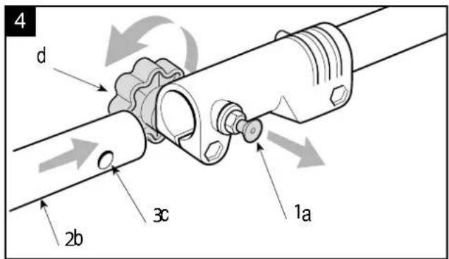

natural_image
Close-up of a metallic pipe fitting with bolts and a central pipe fitting (no text or symbols visible)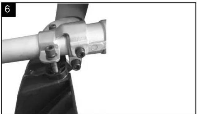
natural_image
Close-up of a mechanical assembly with metal components and bolts (no visible text or symbols)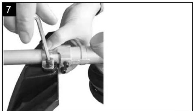
natural_image
Close-up of hands using a tool to adjust or install a mechanical component (no visible text or symbols)
natural_image
Close-up of hands performing a mechanical assembly with a tool, no visible text or symbols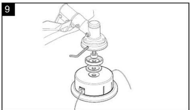
natural_image
Line drawing of a mechanical device with a lever and base mount (no text or symbols)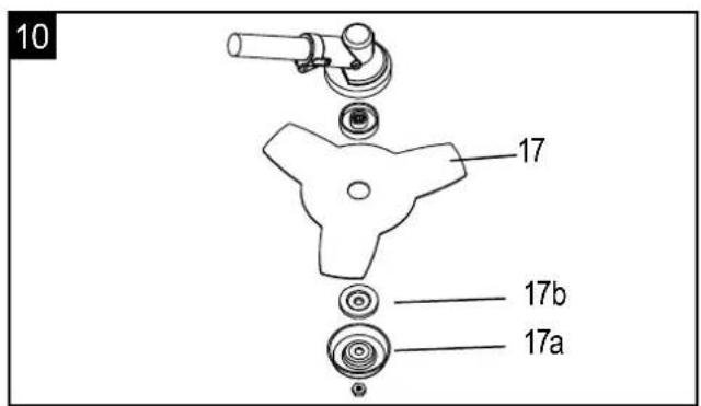
natural_image
Close-up of hands operating a propeller with a rotating knob (no text or symbols visible)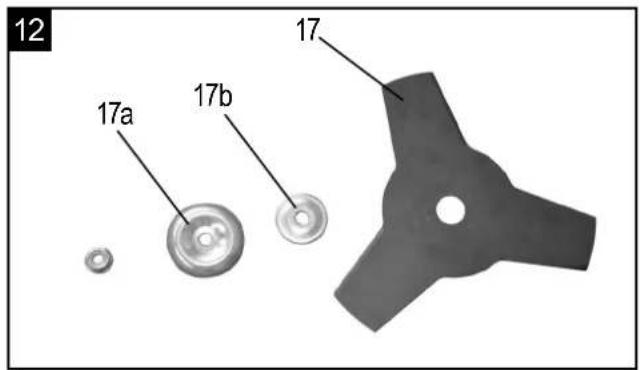
natural_image
Close-up of a mechanical assembly with visible components and wiring (no text or symbols)
natural_image
Close-up of a hand using a handheld power tool to adjust or install a component (no visible text or symbols)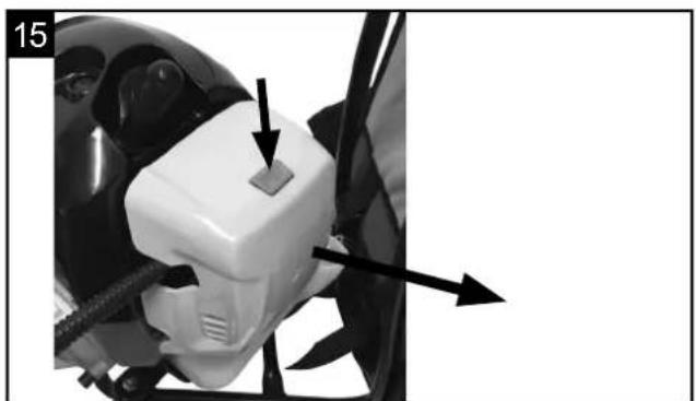
natural_image
Close-up of a white automotive electrical plug with black arrows pointing to its component (no text or symbols visible)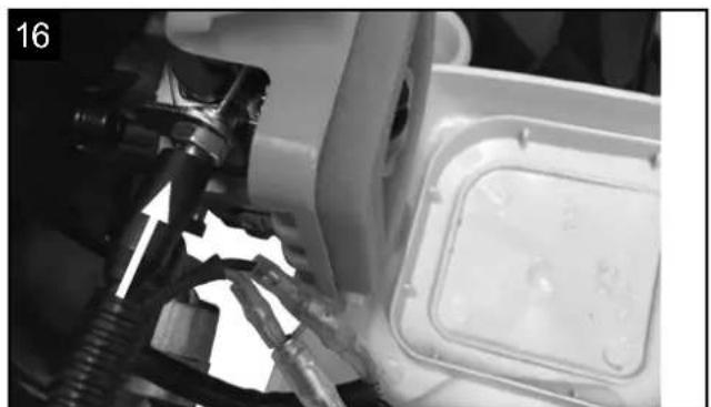
natural_image
Close-up of a mechanical component with a white plastic housing and a black tool inserted, showing no visible text or symbols.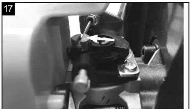
natural_image
Close-up of mechanical components with a white arrow pointing to a component (no visible text or symbols)18

natural_image
Close-up of mechanical components with no visible text or symbols
natural_image
Close-up of mechanical components with connectors and wiring (no visible text or symbols)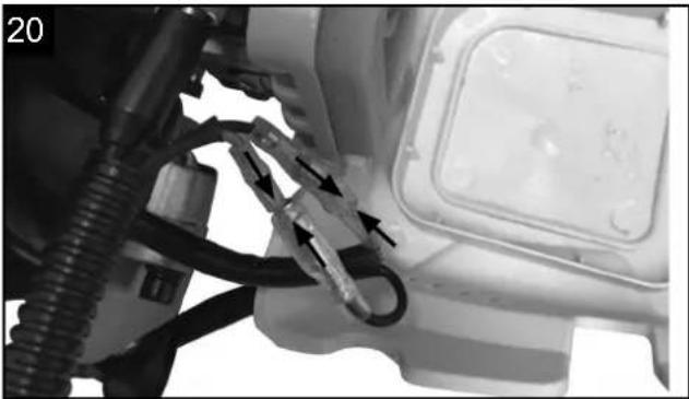
natural_image
Close-up of a mechanical component with hoses and connectors, no visible text or symbols
natural_image
Close-up of a white electric vehicle charging plug with cable, no visible text or symbols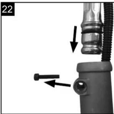
natural_image
Close-up of a mechanical valve assembly with arrows indicating direction (no text or symbols)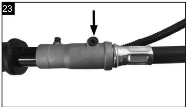
natural_image
Close-up of a mechanical tool with a black handle and cable, showing a small component with an arrow pointing to it (no text or symbols visible)
natural_image
Black-and-white photo of a mechanical device with a curved cable and attached bracket (no visible text or symbols)
natural_image
Close-up of a curved black cable with directional arrows indicating movement or force (no text or symbols)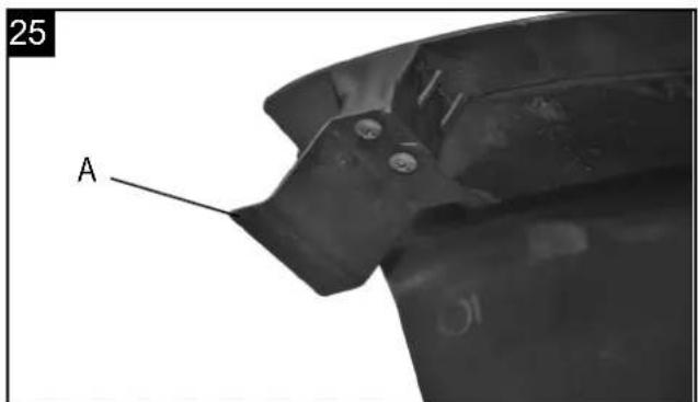

natural_image
Close-up of a white automotive engine component with a black tool inserted, showing mechanical parts and a directional arrow (no text or symbols visible)
natural_image
Close-up of hands using a sewing machine to adjust or install a mechanical component (no visible text or symbols)
natural_image
Close-up of a mechanical device with a knob and adjustment knob (no visible text or symbols)
natural_image
Close-up of a hand holding a circular mechanical component with concentric rings and a curved cable (no text or symbols visible)
natural_image
Two hands holding a mechanical component, one showing internal components and the other with a curved arrow indicating rotation (no text or symbols visible)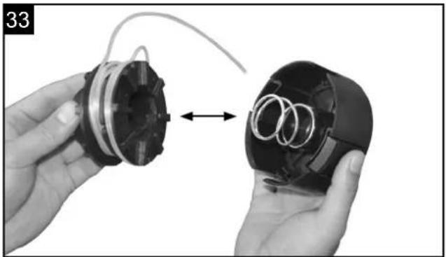
natural_image
Two hands holding a mechanical component with internal rings, one open and one closed (no text or symbols visible)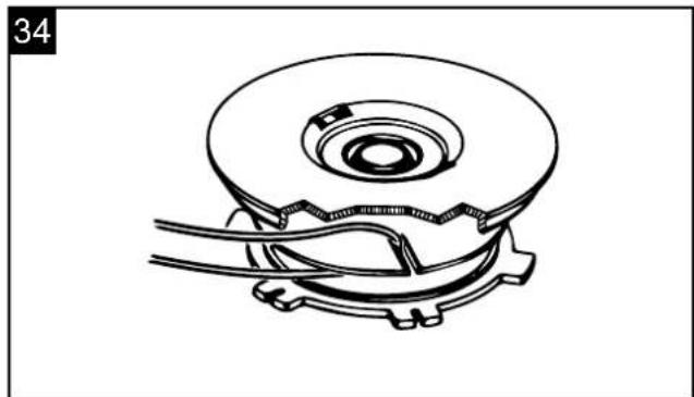
natural_image
Technical line drawing of a mechanical component with no visible text or symbols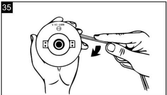
natural_image
Line drawing of a simple outdoor table with a circular top and two legs (no text or symbols)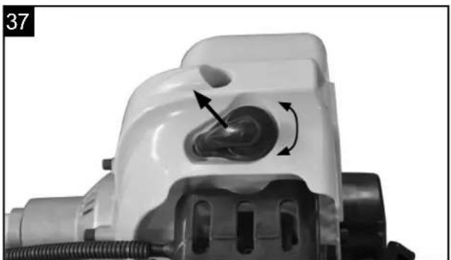
natural_image
Close-up of a white plastic mechanical component with a circular opening and directional arrows indicating motion (no text or symbols)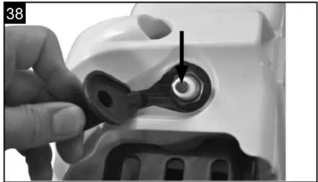
natural_image
Close-up of a hand using a key to adjust a circular component, no text or symbols visible
natural_image
Close-up of a hand operating a small vacuum cleaner with a tool, showing no visible text or symbols.
natural_image
Close-up of a mechanical device with a nozzle and internal components, no visible text or symbols
natural_image
Close-up of a mechanical device with visible components and mounting bracket (no text or symbols)
natural_image
Close-up of a hand adjusting a mechanical component with no visible text or symbols
natural_image
Close-up of a hand inserting a plastic component into a cylindrical pipe (no text or symbols visible)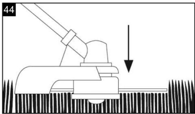
natural_image
Diagram of a mechanical device with a lever and downward arrow, no text or symbols present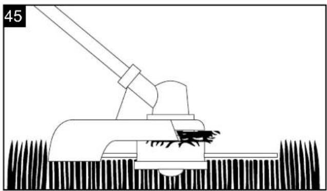
natural_image
Diagram of a mechanical device with a lever and textured base (no text or symbols)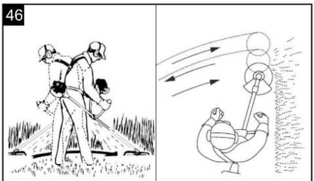


natural_image
Close-up of hands using a mechanical tool to adjust a chain or gear component (no visible text or symbols)
natural_image
Person wearing a black athletic belt with straps and a white arrow pointing to the arm (no text or symbols visible)
natural_image
Person wearing a full-body backpack and T-shirt, viewed from side (no text or symbols visible)
natural_image
Person wearing a full-body medical harness and safety belt, with no visible text or symbols59

natural_image
Close-up of a black athletic belt buckle with directional arrows indicating movement (no text or symbols)60

natural_image
Back view of a black athletic backpack with straps and straps (no text or symbols visible)

natural_image
Mechanical assembly diagram showing a component labeled 'S' with no visible text or symbols beyond the label
natural_image
Close-up of a mechanical component with a cylindrical shaft and meshed base, showing no visible text or symbols.
natural_image
Close-up of a mechanical device with arrows pointing to a component, no visible text or symbols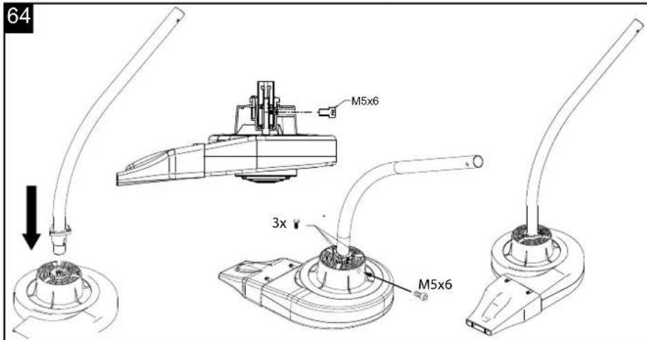
Günzburger Straße 69
D-89335 Ichenhausen
VEREHRTER KUNDE,
Table of contents: Page:
- Introduction 32
- Device description 32
- Scope of delivery 32
- Intended use 33
- Important information, Safety instructions 33
- Technical data 35
- Before starting the equipment 36
- Attachment and operation 36
-
Working instructions 39
-
Maintenance 42
- Storage 44
- Disposal and recycling 45
- Troubleshooting 46
- Declaration of conformity 111
- Warranty certificate 112
Explanation of the symbols on the equipment
 | Read the instruction manual. | |
 | Warning! Gasoline is very flammable. Avoid smoking or bringing any flame or sparks near fuel. | |
 | Warning! Denotes risk of personal injury, loss of life, or damage to the tool in case of non-observance. | |
 | Warning! Risk of injury! Do not let your hands or feet come in contact with the blades when the motor is running. | |
 | Warning! Keep all children, bystanders and helpers 15 meters away from the brush cutter! | |
 | Caution, no saw blades or multipart metal cutting tools! | |
 | Wear protective helmet, ear and eye protection. | |
 | Wear robust footwear when using the device! Wear protective gloves when using the device! | |
 | Warning! The exhaust and other parts of the engine will get very hot during use, do not touch! | |
 | Symbol for refuelling the "MIX GASOLINE" on fuel tank cap. | |
 | Warning! Beware of thrown objects hit by cutting attachments. Never use without properly mounted blade guard. | |
 | The product complies with the applicable European directives and an evaluation method of conformity for this directives was done. | |
 | Caution kickback! | |
 | Electric shock can cause fatal injury. Keep a distance of at least 10 m from power cables. | |
 | Grass trimmer: Cutting circle diameter 450 mm, speed max. 7200 min ^-1 | |
 | Hedge trimmer: Cutting length max. 400 mm, Engine speed min. 4200 min ^-1 | |
 | Brush cutter: Cutting circle diameter 255 mm, speed max. 8500 min ^-1 | |
 | Pole saw: Cutting length max. 254 mm, Engine speed min. 4200 min ^-1 | |
 | Guaranteed sound power | |
 | Fuel tank capacity |
 | Warning! Keep all children, bystanders and helpers 15 meters away from the leaf blower |
 | Warning! Keep all children, bystanders and helpers 15 meters away from the leaf blower |
 | Warning! Beware of thrown objects hit by leaf blower attachments. |
 | Warning! Risk of injury!Never put your hands close to the blades. |
 | Leaf Blower: air speed max. 270 km/h, engine speed max. 10500 min ^-1 |
  | Start lever (choke) "cold start"Start lever (choke) "warm start and work" |
1. Introduction
MANUFACTURER:
scheppach
Günzburger Straße 69
D-89335 Ichenhausen
DEAR CUSTOMER,
We hope your new tool brings you much enjoyment and success.
NOTE:
According to the applicable product liability laws, the manufacturer of the device does not assume liability for damages to the product or damages caused by the product that occurs due to:
- Improper handling,
• Non-compliance of the operating instructions, - Repairs by third parties, not by authorized service technicians,
- Installation and replacement of non-original spare parts,
• Application other than specified, - A breakdown of the electrical system that occurs due to the non-compliance of the electric regulations and VDE regulations 0100, DIN 57113 / VDE0113.
WE RECOMMEND:
Read through the complete text in the operating instructions before installing and commissioning the device. The operating instructions are intended to help the user to become familiar with the machine and take advantage of its application possibilities in accordance with the recommendations. The operating instructions contain important information on how to operate the machine safely, professionally and economically, how to avoid danger, costly repairs, reduce downtimes and how to increase reliability and service life of the machine.
In addition to the safety regulations in the operating instructions, you have to meet the applicable regulations that apply for the operation of the machine in your country. Keep the operating instructions package with the machine at all times and store it in a plastic cover to protect it from dirt and moisture. Read the instruction manual each time before operating the machine and carefully follow its information. The machine can only be operated by persons who were instructed concerning the operation of the machine and who are informed about the associated dangers. The minimum age requirement must be complied with.
In addition to the safety instructions in this operating manual and the separate regulations of your country, the generally recognised technical rules for operating woodworking machines must also be observed. We accept no liability for accidents or damage that occur due to a failure to observe this manual and the safety instructions.
2. Layout (Fig. 1)
- Motor drive unit
- Pole saw
- Hedge trimmer tube
- Power scythe
- Grastrimmer
- Front handle
- Stop Switch
- Throttle lever "lock"
- Starter cable
- Tank
- Throttle lever
- Oil tank for chain saw
- Saw chain
- Chain saw blade
- Cutting unit hedge trimmer
- Adjustment lever
- Cutting blade
- Protection shield (power scythe + grassrimmer)
- Spark plug wrench
- Open-ended spanner (8 mm / 10 mm)
- Allen key (size 4)
- Allen key (size 6)
- 2 x cable ties
- Combined oil/petrol cylinder
- Back pack
- Flexible shaft
- Leaf blower
3. Scope of delivery
- Open the packaging and take out the equipment with care.
- Remove the packaging material and any packaging and/or transportation braces (if available).
- Check to see if all items are present.
- Inspect the equipment and accessories for transport damage. In case of complaints the supplier is to be informed immediately. Complaints received at a later date will not be acknowledged.
- If possible, keep the packaging until the end of the guarantee period.
- Read the operating instructions to make yourself familiar with the device prior to using it.
- After that, please dispose of it in an environmentally friendly way.
- Only use original parts for accessories as well as for wearing and spare parts. Spare parts are available from your specialized dealer.
- Specify our part numbers as well as the type and year of construction of the device in your orders.
⚠ Important!
The equipment and packaging material are not toys. Do not let children play with plastic bags, foils or small parts. There is a danger of swallowing or suffocating!
Fig. 1 + 2
- Motor drive unit (1)
- Pole saw (2/13/14/14a)
- Hedge trimmer (3/15/15a)
- Prush cutter (4/17/17c/18)
- Grasstrimmer (4/5/18)
- Flexible shaft (26)
- Spark plug wrench (19)
- Open-ended spanner (8 mm / 10 mm) (20)
- Allen key (size 4) (21)
- Allen key (size 6) (22)
- 5 x cable ties (23)
• Combined oil/petrol cylinder (24) - Backpack (25)
- Front handle (6 / Fig. 2)
• 4 screws M5 x 35 (Fig. 2) - Cover (Fig. 2)
• 4 nuts M5 (Fig. 2)
4. Intended use
The brush cutter (using the cutting blade) is designed for cutting young trees, strong weeds and undergrowth.
The power trimmer (using the line spool with cutting line) is designed for cutting lawns, grassed areas and small weeds.
The hedge trimmer is suitable for cutting hedges, bushes and shrubs.
The pole-mounted petrol-powered pruner is designed for lopping off tree branches. It is not suitable for extensive sawing work, felling trees or sawing any materials other than wood.
The blower is designed to blow leaves as well as lawn debris such as grass clippings and small twigs. It is not to be used for any other purpose.
The device is only to be used on dry surfaces.
The operating instructions as supplied by the manufacturer must be obeyed to ensure that the equipment is used properly. Any use which is not expressly permitted in the manual may result in damage to the equipment and place the user in serious danger. Be sure to observe the restrictions in the safety instructions.
Please note that our equipment has not been designed for use in commercial, trade or industrial applications. Our warranty will be voided if the equipment is used in commercial, trade or industrial businesses or for equivalent purposes.
Important. Due to the high risk of bodily injury to the user, the petrol power scythe must not be used to carry out the following work: to clean dirt and debris off walkways, or to chop up tree or hedge clippings. Similarly, the petrol power scythe must not be used to level out high areas such as molehills. For safety reasons, the petrol power scythe must not be used as a drive unit for other work tools or toolkits of any kind.
The equipment is allowed to be used only for its prescribed purpose. Any other use is deemed to be a case of misuse. The user/operator and not the manufacturer will be liable for any damage or injuries of any kind resulting from such misuse.
Non-permitted users:
Persons who are not familiar with the operating manual, children, young people under the age of 16 as well as persons under the influence of alcohol, drugs or medication must not operate the unit.
5. Important information
Safety instructions
During transport of equipment
- During transport, always turn off the motor.
- Never carry or transport the power tool with running cutting tools.
- Only ever carry the power tool in work posture:
- Power tool on your back, left hand on the front handle and right hand on the operating lever (also applies to left-handed people), with the cutting tools lowered towards the ground.
- In order to prevent damage and injury, or fuel from leaking, secure the tool against tipping over when transporting it in vehicles. Check the fuel tank for tightness. We recommend emptying the fuel tank before transport.
- The fuel tank must be emptied before shipment.
- Make sure that no persons or animals are close to the working area (minimum distance of 15 m). Grass being cut and thrown up may contain foreign objects such as stones. You are responsible for the safety in your working area, and you are liable for damages to persons or property.
- It is not permitted to either start or use the petrol brush cutter in the vicinity of persons or animals.
- Do not use the tool when you are tired or distracted, or your ability to react is impaired when you are under the influence of alcohol or medication. Inattentiveness may cause serious injuries.
- Use approved safety goggles. Use approved ear protection. Use high-quality safety gloves.
- Use high-quality skid-proof protective shoes with safety steel caps. Never operate the tool wearing sandals, or when barefoot.
• Always wear an approved safety helmet for working in a forest.
- Do not wear wide clothing or jewelry. Wear long trousers to protect your legs. Wear safety helmet for long hair. Loose clothing, jewelry, and long hair can get caught in the moving parts. Wear suitable and durable tight working clothes.
- Keep body parts and clothing away from the cutting tool when you start the engine, or keep it running.
- Make sure you are standing in a stable and secure position during work. Avoid moving backwards with the tool due to risk of stumbling.
- Avoid any unnatural posture.
- When the petrol cutting blade has been operate
for long hours, it may cause a circulatory disorder due to vibration (Raynaud's disease). In this case, it is impossible to specify any length of operation, because it may differ from person to person. The following factors can have an influence on this phenomenon: Circulatory disorders in the hands of the operator, low outdoor temperatures, long hours of operation. Therefore, it is recommended to wear warm protective gloves, and to take breaks at regular intervals.
- The exhaust of internal combustion engines is poisonous and can lead to suffocation, among others. It is not allowed to operate the petrol cutting blade in closed or poorly ventilated rooms.
- Refill the gasoline tank only outdoors, or in well-ventilated areas.
- Gasoline and gasoline vapors are highly flammable. Keep away from flammable materials and sources of ignition, such as ovens or stoves.
- Do not smoke while refueling or operating the tool.
- Immediately wipe away spilled gasoline.
- Start the petrol cutting blade only at a location far away from the place of refueling.
- Always make sure that the cover of the fuel tank is well closed. Look out for possible leakage.
- When the engine is running or the engine is hot, it is not allowed to open the cap of the fuel tank or refill gasoline.
- Open the cap of the fuel tank slowly so that gasoline vapor can escape.
- Make sure the handles are dry, clean, and free of gasoline mixed with oil.
- Do not use the tool without exhaust pipe and when the exhaust pipe guard is not properly installed.
- Do not touch the exhaust pipe, there is a risk of burns.
- Only use the fuel recommended in the manual. Keep gasoline only in containers designed for it, and store it at a safe location.
- While cutting on a slope, always stand below the cutting tool.
- Always make sure no objects or other debris is collecting in the trimmer head, in the protective hood, or in the engine.
• Always switch off the tool before you put it down.
- Do not use any wire, or anything similar in the line spool.
- Only work during daylight, or when the area is illuminated well using lighting.
- Subject the tool to a visual inspection before each use.
- Check, if all screws and connecting parts are tightened.
- Always use both hands to hold the tool.
- Check the tool, and its components and guards for damages, or wear and tear before each use, and have it repaired, if necessary. Never make the devices for protection and safety inoperable. Do not use the tool, when damages or signs of wear become apparent.
- Keep the tools clean and fully functional to ensure
better and safer work.
- Always maintain a safe distance between the tool and your body during work.
- Always switch off the tool when work will be interrupted or the location will be changed; wait until the cutting tools have completely stopped, and turn off the engine.
- Never leave the tool without supervision at the place of work. Store the tool at a safe place when work will be interrupted.
- Persons operating the machine must not be distracted, or one may lose control over the tool.
- Never use the tool during rain, in a humid or wet environment, and do not store it outdoors.
- Should the tool become wet, wait until it is completely dry before you use it again.
- Before starting work, it is recommended to check the objects to be cut for possible foreign objects and to remove them. When despite of this you encounter a foreign object during cutting, switch off the tool and remove this object.
- If the tool is jammed by a foreign object (stones, piles of grass), switch it off, and remove the object using a blunt item. Never use your fingers to remove jammed foreign objects, because this may cause serious injuries.
• Always keep the running tool away from your body.
- Attention: the cutting tool still runs for some time after the tool is switched off!
- Do not overload the engine, and do not use it for work the tool is not designed for.
- Always make sure the ventilation openings are free of dirt.
- Store the tool out of the reach of children.
- Store the tool at a safe and dry location.
- Check the engine for damages after impact, or other damages.
- Keep body parts and pieces of clothing away from the trimmer head when you start the engine, or keep it running.
- Always keep in mind that especially during trimming of lawn edges, gravel enclosures, and similar locations stone and dirt can be hurled away from the cutting line.
- Never cross roads or paths when the tool is switched on.
- Never cut against hard objects such as stone, etc. This way you avoid injuries, and damages to the tool.
- Never use the tool without the guards attached.
- Never use your hands to stop the cutting device.
• Always wait until it stops on its own.
- Hold and guide the trimmer head as close to the ground as possible.
- Only cut grass growing on the ground. Do not cut grass in cracks in walls, growing or on rocks, etc.
- Always make sure no objects, or other debris is collecting in the trimmer head, in the protective hood, or in the engine.
- Only use the tool, when the guard is attached.
• Always switch off the tool, before you put it down.
- Keep in mind that there is risk of injuries in the area of the cutting device intended to cut off the line.
- CAUTION: The cutting tool continues rotating for a few seconds after the engine is turned off.
- Put the tool down only after the cutting tool has completely stopped and the motor is turned off.
- When the cutting tool is damaged, it must be replaced at once.
- Always use the original line only. Never use a metal wire instead of the nylon line.
- Tool and cutting tools must be properly inspected and serviced periodically. Damages must be repaired by a service center.
- Only use accessories recommended by the manufacturer.
- Have your tool serviced only by qualified personnel and by use of original spare parts only. This ensures that the tool will work safely in the future.
Residual risks
- There will always be residual risks, even if you use this equipment according to instructions. The following hazards can occur in connection with the construction and design of this tool.
- Health hazards resulting from swinging of hand and arm if the equipment is used for an extended period and if it is not operated or maintained properly.
- Injuries and material damage caused by ejection of tool attachments which are unexpectedly thrown from the equipment because of sudden damage, wear and tear or improper attachment.
- Warning! This tool generates an electromagnetic field during operation. Under certain circumstances, this field can affect active or passive medical implants. In order to reduce the risk of severe or fatal injuries, we recommend that people with medical implants consult their doctor and the manufacturer of the medical implant before operating the machine.
- Use the gripping spikes for every cut as the starting point and always start the cut with the saw chain running. Make the cut in such a way that the saw does not get jammed in the wood.
- Pay particular attention to branches under tension.
- Always pull the tool out of the wood when the saw chain is running.
- Never work with the tool above shoulder height or with only one hand.
- Always stand away from the falling direction. Position yourself on a slope above the tree to be felled.
- Always stand sideways when carrying out sawing work on a tree which is located on a slope, never work from above or below.
- Always look out for the falling direction of the parts which are cut off.
- Never start the cut with the bar tip and never cut with the bar tip.
- Risk of kickback! There is always a risk of kickback when the bar tip touches the wood or other objects. This makes the chainsaw uncontrollable and it may
be thrown towards the operator with great force.
- Do not use the tool as a lever to move objects.
- Always use the chain guard during transport and storage.
- Secure the tool during transport in order to prevent loss of fuel, damage or injury.
- Warning!
- Keep passers-by away from running equipment but never work by yourself.
- Keep within earshot of others in case you need help.
- Stop the engine immediately when someone approaches you.
- Make sure that the saw chain does not come in contact with foreign objects such as stones, fences, nails and similar. These objects could be ejected and injure the operator or passers-by or damage the saw chain.
- National specifications may restrict the use of the pole saw.
- Do not use the machine within 10 metres of a position from which it can reach high-voltage cables.
Before working on the tool itself (e.g. transport, set-up, retooling, cleaning and maintenance), disconnect the spark plug cap!
6. Technical data
| MTC53-5BP | |
| Technical data | |
| Cutting data grass trimmer | |
| Cutting circle diameter of line mm | 450 |
| Cutting line diameter mm | 2 x ∅ 2.8 |
| Cutting line length m | 4 |
| Speed grass trimmer max. min ^1 | 7200 |
| Cutting data brush cutter | |
| Cutting circle diameter of blade mm | 255 |
| Cutter balde thickness mm | 1.4 |
| Teeth quantity | 3 |
| Speed brush cutter max. min ^1 | 8500 |
| Cutting data hedge trimmer | |
| Cutting circle diameter mm | 24 |
| Angle adjustment ° | +90°/0°/-75° (165°) |
| Cutting length mm | 400 |
| Max. cutting speed max. min ^-1 | 1550 |
| Cutting data pole saw | |
| Bar length mm | 305 |
| Cutting length mm | 254 |
| Cutter bar Type | Kangxin AL10-39-507P |
| Saw chain division | 3/8" |
| Chain type | Kangxin 3/8.50-39 |
| Chain link thickness mm | 1,27 |
| Oil tank capacity cm ^3 | 125 |
| Speed Pole saw min. min ^-1 | 4200 |
| Data leaf blower | |
| Airspeed max. km/h | 270 |
| Air flow max. m ^3 /h | 248 |
| Power unit | |
| Displacement cm ^3 | 51,7 |
| Max. engine output kW | 1,3 |
| Idle speed min ^-1 | 3000 ± 300 |
| Fuel tank capacity cm ^3 | 960 |
| Engine type | 2-stroke engine, air-cooled |
| Weight grass trimmer kg | 12,0 |
| Weight brush cutter kg | 11,9 |
| Weight pole saw kg | 12,5 |
| Weight hedge trimmer kg | 13,2 |
| Weight leaf blowerkg | 12,6 |
Subject to technical changes!
Information concerning noise emission measured according to relevant standards:
Sound pressure L_ A = 97,3 dB(A)
Sound power L_WA = 115.2 dB(A)
Uncertainty K_PA = 3 dB(A)
Wear ear-muffs.
The impact of noise can cause damage to hearing.
Vibration
Grasstrimmer: A_nv = Front 6,67 m/s ^2 Rear 5,67 m/s ^2
Brush cutter: A _hv = Front 6,96 m/s ^2 Rear 7,14 m/s ^2
Hedge trimmer: A_hv = Front 6,62 m/s² Rear 6,62 m/s²
Pole saw: A hv = Front 6,62 m/s ^2 Rear 3,99 m/s ^2 Leaf blower: Ahv = Front 7,37 m/s ^2 Rear 6,95 m/s ^2
Uncertainty K_PA = 1.5 m/s^2
Reduce noise generation and vibration to a minimum!
- Use only equipment that is in perfect condition.
- Maintain and clean the equipment regularly.
- Adopt your way of working to the equipment.
- Do not overload the equipment.
- Have the equipment checked if necessary.
- Switch off the equipment when not in use.
- Wear gloves.
In these operating instructions we have marked the places that have to do with your safety with this sign: △
7. Before starting the equipment
Each time before use, check the following:
- That there are no leaks in the fuel system.
- That the equipment is in perfect condition and that the safety devices and cutting devices are complete.
- That all screws are securely fastened.
- That all moving parts move smoothly.
1 Fuel and oil
Recommended fuels
Use only a mixture of unleaded petrol and special 2-stroke engine oil. Mix the fuel mixture as indicated in the fuel mixing table.
Important: Do not use a fuel mixture which has been stored for longer than 90 days.
Important: Never use 2-stroke oil with a recommended mixing ratio of 100:1. The manufacturer's warranty will be voided in case of engine damage due to inadequate lubrication.
Important: Only use containers designed and approved for the purpose to transport and store fuel.
Pour the correct quantities of petrol and 2-stroke oil into the mixing bottle (see scale printed on the bottle). Then shake the bottle well.
Never use oil for 4-cycle engine or use water cooled 2-cycle engine. It can cause spark plug fouling exhaust part blocking or piston ring sticking.
Mixed fuels, which have been left unused for a period of one month or more, may clog the carburetor or result in the engine foiling to operate property. Put remained fuel into an airtight container and keep it in the dark and cool room.
2 Fuel mixing table
Mixing procedure: 40 parts petrol to 1 part oil Example:
1 | Petrol : 0,025 | 2-stroke oil
5 | Petrol : 0,125 | 2-stroke oil
Warning!
Take care of the emission of exhaust gases.
Always shut off engine before fueling. Never add fuel to a machine with a running or hot engine. Take care of fire!
Only ever refuel the tool outdoors or in sufficiently ventilated rooms. Make sure not to spill fuel or chain oil into the soil (environmental protection). Use a proper base.
8. Attachment and operation
ASSEMBLY
When assembling this machine, please follow the instructions for assembly printed.
1 Assemble the handle on the machine. Fig. 2-3
• Install the front handle as shown on the image 2.
- Make sure that you align the pin with the hole. Tighten the screws only loosely before you have the most comfortable working position set to the risers. The front handle should be aligned as in pictures 2+3 shown, then tighten the screws.
2. Mounting the shaft. Fig. 4
- Pull out the locking pin (a) and press the lower part of the shaft (b) downward until the locking pin engages. The bolt (a) is in the right position when it is fully seated in the bore.
- Lastly, tighten the knob (d) securely.
3. Assemble the safe guard. Fig. 5-7
- Fix the safe guard with hex key and wrench enclosed as standard accessories for tightening the nuts enough. Please see the below pictures showing.
⚠ Warning! Never use the machine without the guard assembled!
4. Assemble and disassemble the cutting head grass trimmer / nylon cutting head. Fig. 8-9
- Release the nut.
Line up the two holes of flange and shield, use one screw driver to hold the flange as below and turn the socket wrench clockwise, the nut will be released.
• Fit the Nylon cutting head.
Remove another shield after release the nut. Still hold the flange, take the Nylon cutting head on the shaft and rotate counter-clockwise, the Nylon cutting head is fitted. Fig. 9
- Release the Nylon cutting head.
Use screw driver to hold flange and then rotate the Nylon cutting head clockwise, it will be replaced.
Brush cutter / Cutter blade
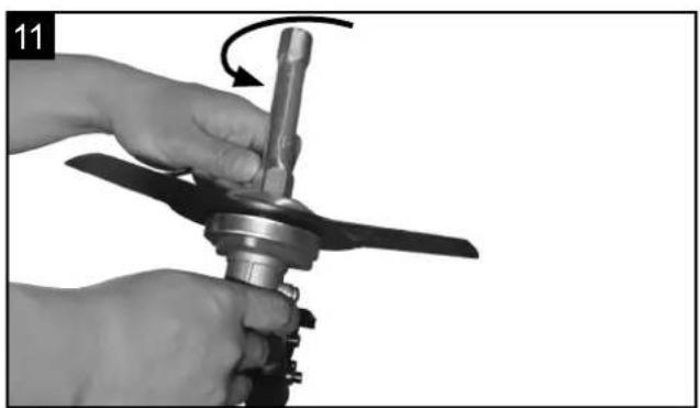
• Fit the blade. Fig. 10-12
Take the outer flange off after release the nut, then put the blade (17), outer flange (17b), shield (17a) and nut according to priority as below picture. Note the blade rotation direction needs be same as below picture. Use screw driver to hold flange and tighten nut counter-clockwise, ensure the nut is tightened enough.
- Release blade. Use screw driver to hold flange and release nut, the blade can be took off.
⚠ Warning!
Please make sure the cutting head has been assembled correctly before use!
OPERATION
When working with the equipment as grass trimmer and brush cutter, the appropriate plastic guard hood for cutting blade mode or cutting line mode must be fitted to prevent objects being thrown out by the equipment.
The integrated blade (A) in the cutting line guard hood automatically cuts the line to the optimum length. Fig. 25
5 Mounting the flexible shaft Fig. 13 - 24
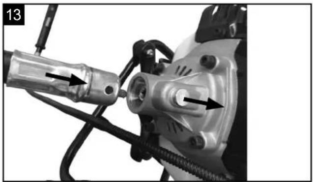
- Pull the locking bolt out and affix the flexible shaft to the motor until the locking bolt locks in. Fig. 13, 14
- Open the air filter cover, screw the accelerator cable in as shown and attach to the throttle valve. Fig. 15-17
- Secure with a counter nut. The accelerator cable must be able to move from idle to full acceleration freely. Fig. 18
- Connect the ignition interruption cables as shown in figure 19, 20.
- Secure the air filter cover with a screw again. Fig. 21
- Remove the screw from the handle, insert the other side of the flexible shaft into the handle and use the screw to affix it to the handle. Fig. 22, 23
- Use cable ties to affix the accelerator cable to the flexible shaft. Fig. 24
6. Fit the belt. Fig. 56 - 60
- Wear the shoulder strap. Fig. 56 - 58
• Balance the machine when the tool is switched off. - When standing in a normal working posture, the blade should touch the ground during normal working position.
- To fit the backpacks to your body size adjust the straps at the carrying strap. Fig. 59
- Safety button at the carrying strap Fig. 60 ATTENTION! In an emergency, the safety button (m) can be pressed from the harness. The machine then detaches immediately from the carrying strap and falls to the ground.
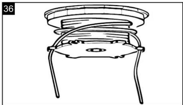
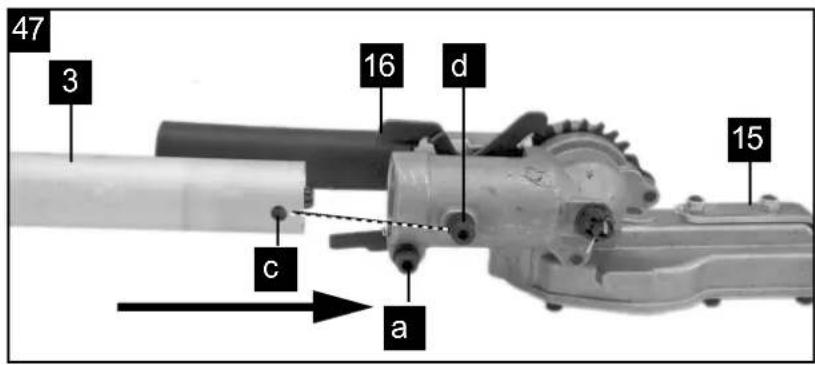
7. Mounting the hedge trimmer Fig. 47-49
- Remove the screw (d), align the holes (c) so that they are flush and screw the screw (d) back in.
- Place the hedge trimmer (15) precisely as shown in Figure 47 on the connecting rod (3).
- Tighten with screw (a).
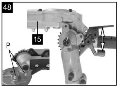
- Adjust the slope by unlocking the lock (Fig. 48)
- The hedge trimmer can be tilted from 0^ to 90^ (Fig. 49).
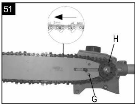
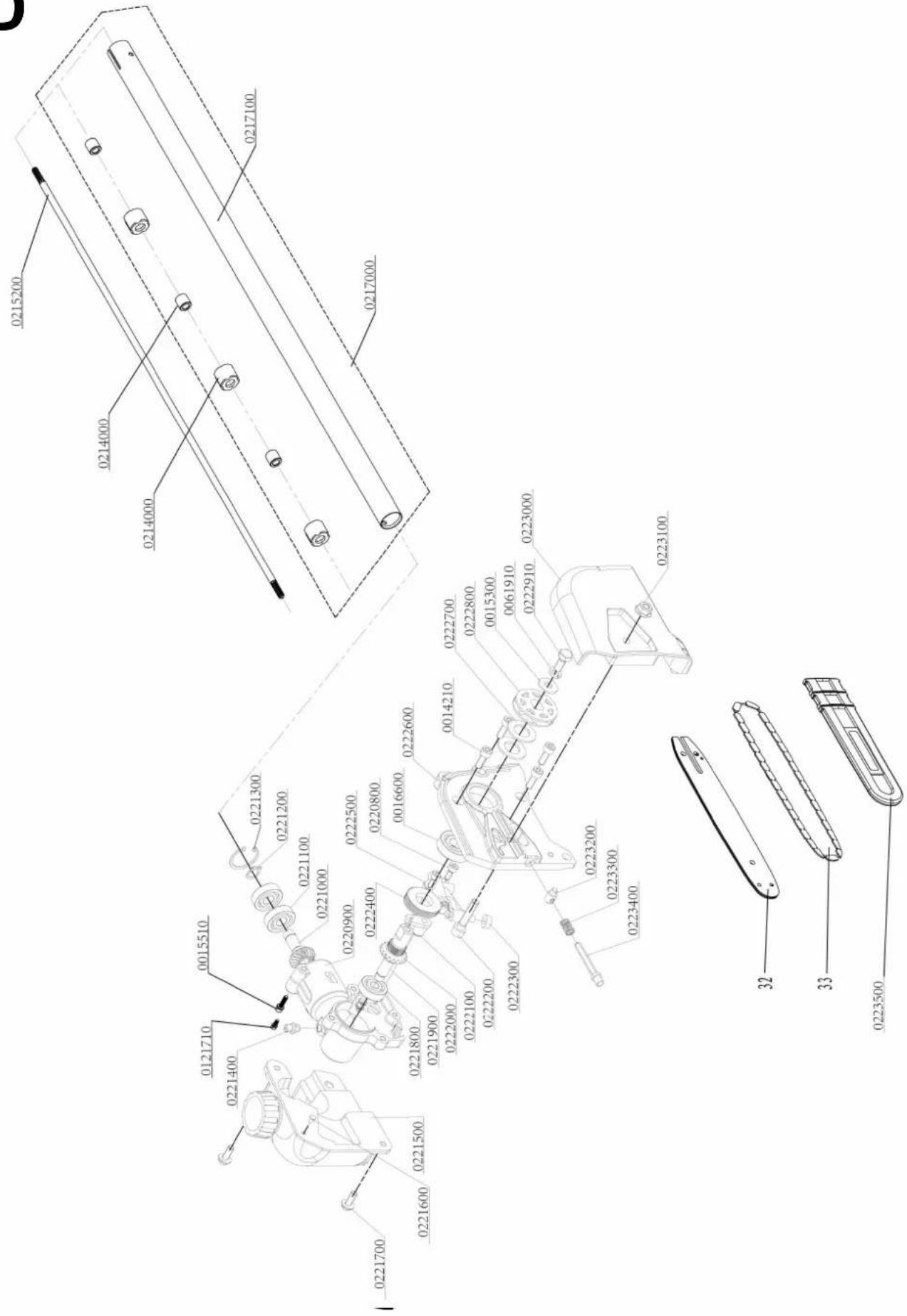
8. Fitting the cutter bar and the chain Fig. 50 - 52
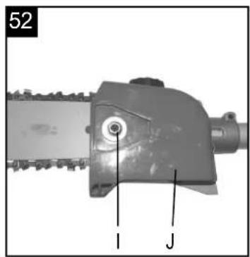
- Remove the chain wheel cover (Fig. 52/ Item J) by undoing the fastening nut (Item I). Lay the chain (Item F) as shown into the groove which runs around the cutter bar (Item E).
- Note the alignment of the chain teeth (Fig. 51). Insert the cutter bar as shown in Fig. 51 into the mount at the gear unit.
- Place the chain round the chain wheel (Item H). Make sure that the teeth of the chain engage securely in the chain wheel. The cutter bar must be hooked into the chain tensioning bolt (Item G).
- Fit the chain wheel cover
Important! Do not fully tighten the fastening screw until after you have adjusted the chain tension.
Tensioning the chain Fig. 52 - 55
Important! Always pull out the spark boot plug before performing any checks or adjustments.
- Undo the fastening screw (Item I) of the chain wheel cover by a few turns (Fig. 52).
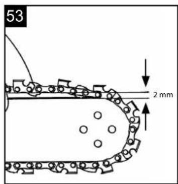
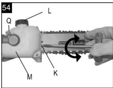
- Adjust the chain tension with the chain tensioning screw (Fig. 54/ Item K). Turning the screw clockwise increases the chain tension, turning it counterclockwise decreases the chain tension. The chain is correctly tensioned if it can be raised by around 2mm in the middle of the cutter bar (Fig. 53).
- Tighten the fixing screw of the chain wheel cover (Fig. 55).
- Important! All the chain links must lie properly in the guide groove of the cutter bar.
Notes on tensioning the chain:
The chain must be properly tensioned to ensure safe operation. When the saw chain can be raised by around 2 mm in the middle of the cutter bar, you know that the chain tension is ideal. During cutting, the temperature of the chain rises and its length changes. It is important therefore to check the chain tension at least every 10 minutes and to adjust it again as required. This applies in particular to new saw chains. When you have finished working, slacken the chain again as it will shorten when it cools down. This will help to prevent damage to the chain.
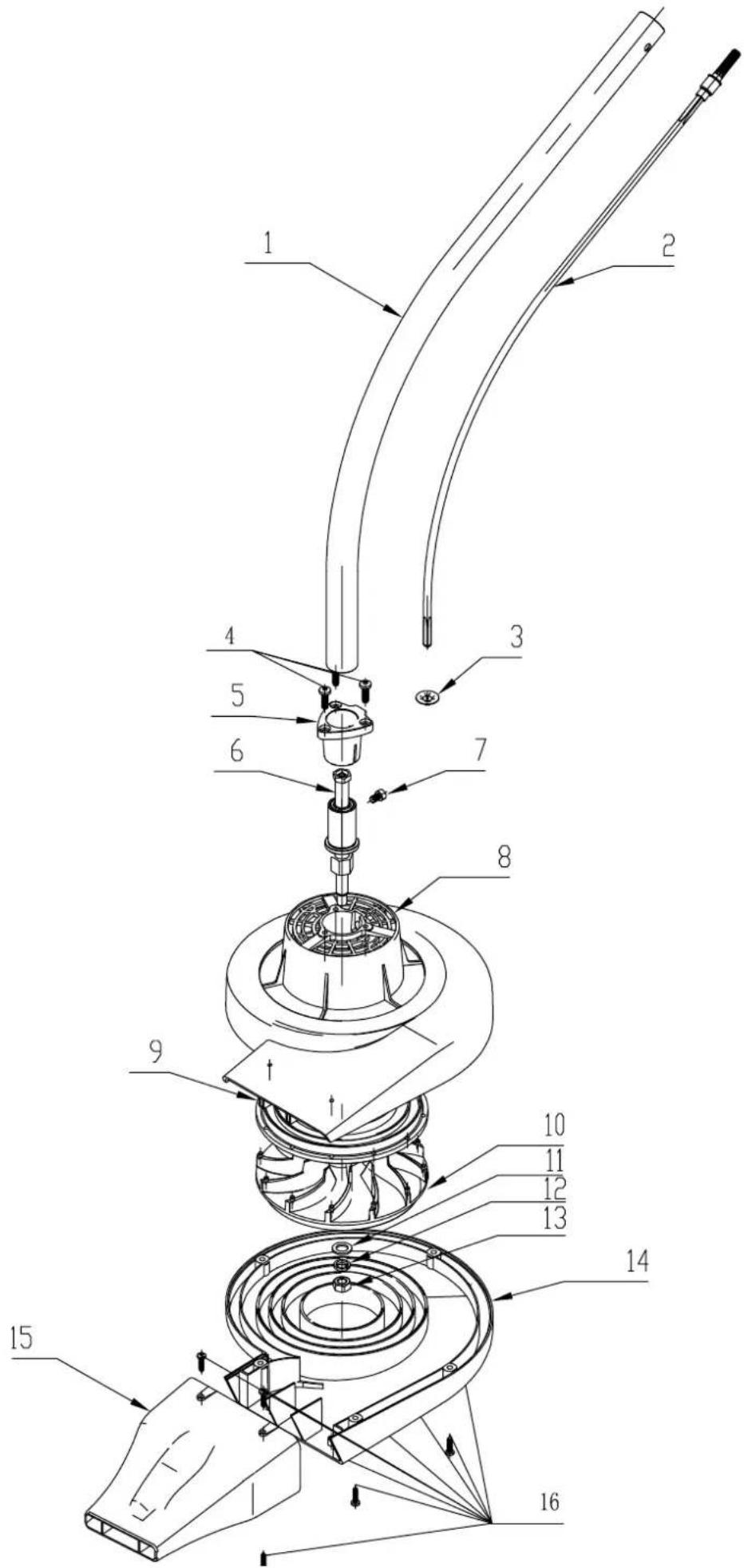
9. Assemble leaf blower
Assemble the leaf blower as shown in Figs. 63-64.
10. Filling with fuel
⚠ Danger of injury! Fuel is explosive!
Turn the motor off and let the machine cool down. Wear safety gloves.
Avoid contact with skin and eyes.
Make sure you observe the "Safety Instructions" paragraph.
- Only ever refuel the tool outdoors or in sufficiently ventilated rooms.
- Clean around the filling area. Contaminants in the tank will cause operating problems.
- Before refuelling, shake the container with the fuel mixture.
- Carefully open the fuel filler cap (B) so that potential pressure can be release. Fig. 26
- Carefully pour in the fuel mixture to the lower edge of the filler.
- Close the fuel filler cap (B). Ensure the fuel filler cap closes tightly.
- Clean the fuel filler cap and the area around it.
- Check the tank and the fuel line for leaks.
- Before starting the motor, remove yourself from the fuelling place by at least three metres.
Draining fuel. Fig. 43
Only ever empty the tank outdoors or in well-ventilated rooms. Make sure not to spill fuel or chain oil into the soil (environmental protection). Use a proper base.
- Hold a collection container beneath the fuel drain bolt.
- Unscrew the tank cap and remove it.
- Allow the fuel to run out completely.
- Screw the tank cap on firmly by hand.
11. Start on the unit
Do not start the unit until it has been completely assembled.
⚠ Danger of injury!
Only start the petrol multi garden tool if an attachment is connected! Remove the appropriate transportation protection and inspect the unit in good working condition. Never use a damaged, poorly adjusted or serviced or not completely and securely assembled device.
Check before use!
- Check the safe condition of the device:
- Check the device for leaks.
- Check the device for visual defects.
- Check that all parts of the device have been securely fitted.
- Check that all safety devices are in proper condition.
Start Fig. 60, 26 - 30
Once the machine has been set up properly, start the engine as follow:
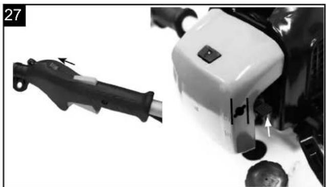
- Turn the engine switch to the ON position. Fig. 27
- Put the choke lever on the position. Fig. 27
- Press the fuel pump more than 5 times. Fig. 26
-
Pull the recoil starter handle (9) 3-5 times to start the engine. Fig. 28 Never place feet on the shaft or kneel on it.
-
Wait a while adjust the choke lever to position. Fig. 29
-
When the engine is running and idling. First press the lock off lever (8) and then switch the throttle lever (11) on, the machine will be working. Fig. 30
-
If meet any problems, press the engine switch to off position, the machine will stop running. If need stop cutting head working, release the throttle lever (11). Fig. 30
-
In an emergency, the safety button (m) can be pressed from the harness. The machine then detaches immediately from the carrying strap and falls to the ground. Fig. 59
-
If the machine is hot, the throttle level can be adjusted to ON position directly when re start the machine. Without choke
Note: If the engine does not start up even after several attempts, read the section „Engine troubleshooting“.
Note: Always pull the starter cord out in a straight line. If it is pulled out at an angle, then friction will occur on the eyelet. As a result of this friction, the cable will become frayed and will wear away faster. Always hold the starter handle when the cable retracts.
Never allow the cable to snap back when it has been pulled out.
Note: Do not start the motor in tall grass.
⚠ Attention: When the engine has been switched off, the cutting unit continues running for several seconds therefore do not touch the cutting unit until it has come to a standstill!
9. Working instructions
Working with brush cutter / grass trimmer
- When you work with the petrol brush cutter for the first time, familiarize yourself with the operation and control of the petrol cutting blade without running engine.
- The design of the petrol brush cutter allows for operation only at the right side of the user's body.
- Keep the petrol brush cutter firmly with both hands on the handles.
- Hold the operating handle with your right hand and the handle on the shaft with your left hand.
- Always make sure that the cutting tool continues to rotate briefly after the throttle has been released.
- Always so that the cutting tool no longer turns in a proper engine idle not press down the throttle.
- Always work with high speed so you have the best cutting results.
- Move the device with a uniform curved movement from left to right and back again. Then cut the next section. Fig. 46
Attention: Always move the device back into the original position before cutting the next path. - Poke when working on a stone or a tree, turn off the engine and remove the spark plug then examine the petrol brush cutter for damage.
- Caution: Always be extra careful when working in difficult terrain and slopes. Cut tall grass gradually so as not to overload the unit.
- Always wear safety glasses and hearing protection and a safety helmet.
- Use the cutting blade to comb through brushwood, rank growth, young tree populations (trunk diameter of maximum 2 cm), and high grass.
- While using metal cutting tools, there is generally a risk of recoil, when the tool hits a solid obstacle (stones, trees, branches, etc.). Thereby, the tool is hurled backwards against the rotating direction.
- To cut rank growth and brushwood, you "immerse" the cutting blade from the top. This chops the material to be cut
- Attention! The cutting unit is still running! Do not stop the cutting unit with your hand.
- Keep the cutting unit of the string trimmer away from feet.
CAUTION: Be especially careful, when using this working technique, because the further away the cutting tool is from the ground, the higher is the risk that objects to be cut and particles will be hurled sideways.
Mowing with grass trimmer
- Use the plastic line cassette for a clean cut also at uneven edges, fencing posts, and trees.
- Carefully advance the trimming line to an obstacle, and use the tip of the line to cut around the obstacle. When the trimming line comes into contact with stones, trees, and walls, the line wears out or breaks off ahead of time.
- Never replace the nylon line with a metal wire. RISK OF INJURIES
Mowing with grass trimmer
- Use the plastic line cassette for a clean cut also at uneven edges, fencing posts, and trees.
- Carefully advance the trimming line to an obstacle, and use the tip of the line to cut around the obstacle. When the trimming line comes into contact with stones, trees, and walls, the line wears out or breaks off ahead of time.
- Never replace the nylon line with a metal wire. Risk of injuries
Automatic thread trimming Fig. 44
The petrol cutting blade is delivered with a filled line cassette.
This line will wear out during work. To feed new line, forcefully press the head of the line cassette onto the ground while the engine is running at working speed.
The line is automatically fed due to centrifugal force. The knife at the line guard will shorten the trimming line to the correct length.
Run the trim line approach cautiously to an obstacle and cut with the tip of the line around the obstacle.
Working with hedge trimmer
- The hedge trimmer may be used only for cutting hedges, bushes and shrubs
- Hold the hedge trimmer with both hands on a safe distance from the body.
- Due to its double sided knives the hedge trimmer can be guided forward and backward or by oscillating movements from one to another side.
- At first cut the sides of the hedge and then the upper edge.
- Cut the hedge from the bottom up.
- Cut the hedge in trapezium shape.
- Remove unconditionally any foreign objects out of the hedge (e.g. wires) as these can damage the knives of the hedge trimmer.
- Attention! The blades are still running! Do not stop the blades with your hand.
Angle adjustment
By swivelling the cutter head, the hedge trimmer can be adjusted to the working conditions from +90° to -75°. Fig. 49.
- Warning! Adjust the angle only when the motor has been turned off.
- Push both levers down and put the cutter head in the required position. Fig. 49
- Release both levers until they click into place in the notch.
- Before use, check that the adjustment levers have clicked into place properly. Fig. 49
Oil the blades and the angle adjustment each time before starting work, with environmentally friendly lubricant.
Regularly oil the blades during working hours as well.
Warning! Oil the tool only when the motor has been turned off.
Caution: Incorrect use and misuse can damage the bush cutter and cause severe injuries because of pieces hurled away.
To minimize the risk of accidents by use of the cutting blade, take note of following points:
- Never cut shrubbery or wood whose diameter is larger than 2 cm.
- Avoid contact with metal bodies, stones, etc.
- Periodically check the cutting blade for damages. Never continue to use a damaged cutting blade.
- When the cutting blade becomes apparently blunt, it must be sharpened according to instructions. When the cutting blade is apparently out of balance, it must be replaced.
Working with pole saw
Oiling of the chain and bar
It is recommended to use commercial chain oil.
- Remove the oil tank cap. (Fig. 54 / L)
- Fill the chain oil tank (Fig. 54 / M)) to 80% with chain oil.
- Close Oil tank cap (Fig. 54 / L)
Oil Supply Control
Always make sure that the automatic oil system is working properly. Always ensure the oil tank is full.
During sawing work, the guide and the chain must always be sufficiently oiled to reduce friction with the chain bar.
The chain bar and the chain must never be without oil. If you operate the chain dry or with too little oil, the cutting performance will decrease, the service life of the chain bar will reduce, the chain will become blunt quickly and the guide will wear rapidly owing to overheating. You can detect a lack of oil from smoke development or the guide changing colour.
To check the chain lubrication keep the chain on a piece of paper and give full throttle for a few seconds. On the paper the quantity of oil can be checked. The saw chain must always throw off a little oil. After a few seconds, a slight oil trace must be visible.
Make sure that there is always enough oil in the tank because chain lubrication is always on.
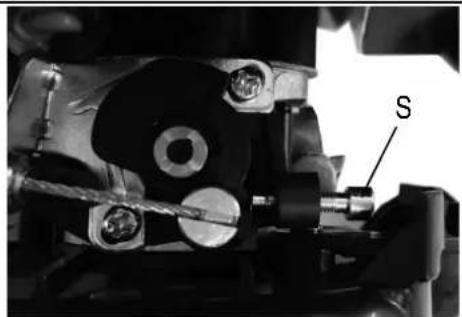
Automatic chain lubrication - Settings possible! Fine adjustment, Fig. 61
You can reduce or increase the quantity of oil using the screw (R).
Clockwise - oil quantity is reduced (-)
Anti-clockwise - oil quantity is increased (+)
Precautions for Saw procedure
Never stand under the branch you want to saw. Use special caution when working with branches under tension and splintering wood. Possible risk of injury caused by falling branches and catapulting pieces of wood. In general, it is recommended to set the pruning saw at an angle of 60^ to the road.
Keep both hands well with the device during the cutting process and pay you up to an equilibrium position and a good level.
- Never try to use your tool with one hand. The loss of control of your tool can cause serious injury or death. Never work on a ladder, a tree branch or other unstable surfaces.
- Never cut with the upper edge or the tip of the cutter bar.
- Make sure that the chain tension is always correctly adjusted.
- Practice for guiding the device slight pressure, but you do not overload the motor.
Clear the work area before cutting interfering branches and undergrowth. Then you create a retreat area, far from the spot where the cut branches fall on, and remove any obstacles there. Keep the work area clean, remove the cut branches immediately. Pay attention to your point, wind direction and the possible direction of fall of the branches. Be prepared that fallen branches can strike back. Place all other tools and equipment at a safe distance from the branches to be cut, but not in the retreat area.
Always observe the condition of the tree.
Look for rot and decay in the roots and branches. If they are rotten inside, they can break off and fall down unexpectedly during cutting.
You could also attend by fractured and dead branches out, which is solved by the shake and fall on you.
For very thick or heavy branches you first make a small incision below the branch before you work from the top down to avoid chipping.
Basic cutting technique
Heavy branches break off easily when sawing. They tear long strips of bark away from the trunk, which damages the tree sustainably. The following section technique can significantly reduce this risk:
- Saw the first branch about 10 cm from the trunk.
- Put in about 15 cm from the base of the top of a further section.
- Saw until the branch breaks. The risk of injury on the trunk is no.
- Finally, remove with a clean cut from the top of the trunk along the remaining.
- Thus, the damage to the tree are kept as low as possible, we recommend the interface additionally to seal with grafting wax.
Hazards by reactive forces
Reactive forces occur during operation of the saw chain. The forces which are applied to the wood are against the operator. They occur when the moving chain comes into contact with a fixed object such as a branch or is pinched. These forces can lead to a loss of control and injury.
Understanding the origin of these forces can help you to avoid the scare and the loss of control. This saw is designed to make the return effects are not as noticeable as with traditional chain saws.
Always still keep a firm grip and a good level to maintain control of the tool in doubt.
The most common effects are:
- setback
- recoil,
- retreat
Kickback
The setback can occur when the moving saw chain meets at the upper quarter of the guide rail on a solid object or is pinched.
The cutting force exerted on the chain from the saw, a rotational force in the opposite direction to the chain travel. This leads to an upward movement of the guide rail.
Avoid kickback
The best protection is to avoid situations that lead to setbacks.
- Keep the position of the upper guide rail always in mind.
- Leave this place never come into contact with an object. Cut anything with it. Be especially careful near wire fences and cutting small, hard knots, in which the chain can easily pinch.
- Cut only one branch at a time.
Withdrawal
The withdrawal occurs when the chain on the underside of the bar suddenly stuck because it is jammed or encounters a foreign object in the wood.
The chain then pulls the saw forward. The withdrawal often happens when the chain is not running at full speed when in contact with the wood.
Avoid withdrawal
Be aware of the forces and situations that can lead to jamming of the chain on the underside of the bar.
Always start with running at full speed chain to cut.
Recoil
The recoil occurs when the chain on top of rail suddenly stuck because it is jammed or encounters a foreign object in the wood. The chain can jerkily hold the saw against the operator. Rebounds happen often if the top rail is used for cutting.
Avoid recoil
Be aware of the forces and situations that can lead to jamming of the chain on top of rail.
Do not cut more than one branch at a time.
Do not tilt the rail to the side when you pull them out of a cutting gap, since the chain could get caught otherwise.
Operation Leaf blower
- Do not smoke while refueling or operating equipment.
- Do not touch or let your hands or body come in contact with a hot muffler or spark plug wire.
- Due to the danger of exhaust fumes, never operate blower in a confined or poorly ventilated area.
- Use the tool only in broad daylight or in well-lit conditions.
- Do not underestimate the forces involved. Make sure you stand squarely and keep your balance at all times.
- If possible, avoid using the tool on wet grass.
- Ensure that you maintain a steady foothold particularly while working on slopes.
• Always walk. Never run.
• Always keep the ventilation opening clean. - Never direct the blow hole at persons or animals.
- The machine may only be used at reasonable times of the day, i.e. not in the early morning or late evening when it will be a nuisance to other people. Permitted times of use specified by local authorities must be observed.
- The machine must be run at the lowest possible motor speed required to carry out the work.
- Remove all foreign objects with a rake and brush before starting any blowing work.
- Where conditions are dusty, dampen the surface a little or use a sprinkler attachment.
- Use the full-length blower nozzle extension so that the air current can work near to the ground.
- Watch out for children, pets, open windows etc. and blow the foreign objects safely away from them.
- If the device makes abnormal noises or has unusually high levels of vibration, it must be checked. Unusually high levels of vibration can injure the operator and damage the unit.
- Never operate the appliance with defective guards or shields, or without safetydevices, for example debris collector in place
- Do not expose the hot engine to flammable materials
- The Blower can be used to blow debris from patios, paths, driveways, lawns, bushes and borders.
- Select the blow function using the selector lever on the side of the machine and switch on.
- Alternatively hold nozzle just above the ground and swing the machine from side to side, moving forwards and direct the nozzle at the debris to be cleared.
- Blow the debris into a convenient heap
10. Maintenance
WARNING: Always wear protective gloves when working on or around cutting tools.
For non-use, transport or storage always attach the transport guard to all cutting tools. Fig. 1 (14a, 15a, 17c)
Before performing any maintenance or cleaning work, always turn off the engine and pull out the spark boot plug.
- Do not spray the unit with water. It damages the engine.
- Clean the unit with a cloth, hand brush, etc.
- Use a moist piece of cloth to clean the plastic parts. Do not use any cleaning agents, solvents, or sharp objects.
- During the course of work, wet grass and weed wraps around the drive shaft below the cutting guard for technical reasons. Remove this, otherwise the engine will overheat because of too much friction. Fig. 45
Regular checks
Keep in mind that following specifications relate to normal usage. Owing to circumstances (longer periods of daily work, severe dust exposure, etc.), the specified intervals will become correspondingly shorter.
- Before starting work, after tank filling, after impact or dropping:
Check the cutting tools for secure seating, general visual check for cracks and damage. - Immediately replace damaged or blunt cutting tools, even in the event of minor hairline cracks.
- Sharpen cutting tools (also when required).
• Weekly inspection:
Lubrication of gear (also, if necessary). - If necessary:
Retighten accessible fastening screws and nuts. You will avoid excessive wear and tear and damages of the tool, when you follow the instructions in this manual.
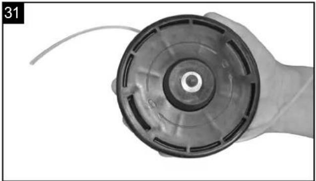
Replacing the line spool/cutting line Fig. 31 - 36
- Pull off the line guard cap from the line spool (5) by forcefully pressing between the retaining plates.
- Remove the spool with line remaining and the compression spring.
- Remove the used up spool.
- Take the new line spool and pull out 10 cm at both lines each.
- Now, place the line spool (5) on the tapered spring, and guide both lines each through the round metal lugs at the line spool housing.
- Then place the spool cover on the new line spool (5). Turn it so that the plates of the spool cover are pushed with the springs in the line spool housing.
-
Now, press the spool cover together with the line spool, until it engages in the line spool housing.
-
The knife (A) in the protective hood (18) shortens the trimming line to the correct length, when the engine starts again.
Grinding the safety hood blade Fig. 25 A
The safety hood blade can become blunt over time.
- When you notice this, undo the screw holding the safety hood blade on the safety hood.
- Clamp the blade in a vise.
- Sharpen the blade with a flat file and make sure that the angle of the cutting edge is not altered in the process. File in one direction only.
- Important! Install the cutting knife again
Replacing and resharpening the cutting blade at the end of the mowing season
Grinding the cutting blade (17)
If the blades become slightly dull, you can sharpen them yourself.
- Fasten the blade in a vice.
- Grind all 3 cutting unit blades using a flat file and make sure to maintain the angle of the cutting edge. ( 25^ ) Only file in one direction.
- Replace the blades after sharpening them five times at the latest.
Replacing and resharpening the cutting blade at the end of the mowing season always resharpen the cutting blade or, if required, replace the cutting blade with a new one.
Unbalanced blades will cause the brush cutter to vibrate violently-risk of accident!
Lubricate angle transmission, Brush cutter Fig. 8 (O)
Lubricate with lithium-based grease. Remove the screw and put in the grease, turning the shaft manually until grease emerges, then replace the screw.
Attention! Fill only a small amount of grease. Do not overfill.
Change and clean the spark plug Fig. 37 - 38
Check the spark plug air gap at least once a year or when the engine starts poorly. The correct gap between ignition flag and ignition contact is 0.25"/0.63 mm.
- Wait until the engine has cooled down completely.
- Pull the spark plug cap off the spark plug, and use the supplied spark plug wrench to remove the spark plug by turning.
- When the electrode is severely worn out or reveals a strong incrustation, the spark plug must be replaced with an equivalent plug.
- A strong incrustation of the spark plug can be caused by: Amount of oil is too high in the gasoline mix, poor oil quality, old gasoline mix, or plugged up air filter.
-
Screw the spark plug by hand completely into the thread. (Avoid jamming it)
-
Use the supplied spark plug wrench to tighten the spark plug.
- When using a torque wrench, the tightening torque is 12-15 Nm.
- Plug the spark plug socket correctly on the plug.
Clean the air filter Fig. 39 - 42
Soiled air filters reduce the engine power by supplying too little air to the carburetor. Dust and pollen plug up the pores of the filter made of foamed plastic. Regular checks are therefore essential.
- Unclip the air filter cover and remove the sponge filter element.
- To avoid objects falling into the air tank, replace the air filter cover.
- Wash the filter element in warm soap water, rinse and allow drying naturally.
Important: Never clean the air filter with petrol or inflammable solvents.
In order not to shorten the service life of the engine, a damaged air filter must be replaced at once.
⚠ Warning!
Never run the engine without the air filter element installed.
Care of the guide rail
Turn the rail around every time you have the chain sharpened or replaced. This will avoid a one-sided wear of the rail, especially at the top and bottom.
Regularly clean
1 = the opening for the oil supply
2 = the oil passage
3 = the raceway groove of the rai
Servicing and sharpening of saw chain
The correct sharpened chain
A properly sharpened chain goes way through the wood and it requires very little pressure. Do not work with a dull or damaged chain. It increases physical exertion, increase the vibrations and leads to unsatisfactory results and higher wear.
- Clean the chain.
- Check it.
- Replace damaged or worn parts with matching spare parts they are in the shape and size of the original parts as necessary.
- Sharpening a chain should be performed only by experienced users!
Notice. Below the angle and dimensions If the chain is not properly sharpened or the depth is too small, there is a higher risk of reversion effects and resulting injuries! The chain cannot be fixed on the
guide rail. It is therefore best to remove the chain from the rail and then sharpen.
- Select the appropriate tools for the chain pitch sharpening tool. See "Specifications" for the allowed chain pitches.
The chain pitch (for example 3/8") is highlighted in the depth of each blade.
Use only special files for chain saws! Other files have the wrong shape and the wrong cut.
Select the file according to the diameter of your chain pitch. Make sure to observe the following angle when sharpening the chain diameter.
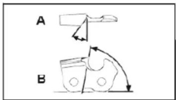
A = filing angle
B = the angle of the side plate
The angle must also be maintained for all knives.
For irregular angles, the chain is run irregularly, wear quickly and break down prematurely.
Since these requirements can only be met with sufficient and regular exercise:
- A File Holder must be used when sharpening the saw chain by hand. The correct filing angle marked on it.
- Hold the file horizontally (at a right angle to the guide rail) and file according to the angle mark on the file holder. Support the file holder on the top plate and depth gauge.
- File down. The knife is always from the inside to the outside
- The file sharpens only in forward motion. Lift it off in the backward motion.
- Do not touch the dynamic links with the file.
- Turn the file regularly continue to avoid a onesided wear.
- Remove to remove a piece of hard wood, bones raw edges.
All knives must have the same length, otherwise they will also vary. As a result, the chain is irregular and it increases the risk of going broke.
Lubricate the drive, pole pruner
Lubricate the drive every 10 to 20 operating hours.
-
Apply the grease gun to the grease nipple Fig .54 (Q).
-
Squeeze some grease into it.
Attention! Fill only a small amount of grease. Do not overfill.
Check the hedge trimmer for obvious faults such as:
- loose attachments
- worn or damaged components
- bent, broken or damaged cutting tools
- correctly attached and working covers and safety devices
- wear, in particular, cutting tool play
Immediately replace damaged or blunt cutting tools, even in the event of minor damage.
Oiling the gears
Oil the gears every 10 to 20 operating hours.
1 Position the grease gun at the lubricating nipples
Fig. 48 (P).
2 Insert some grease.
Attention! Fill only a small amount of grease. Do not overfill.
Oil the cutting tools and the angle adjustment with environmentally friendly lubricant.
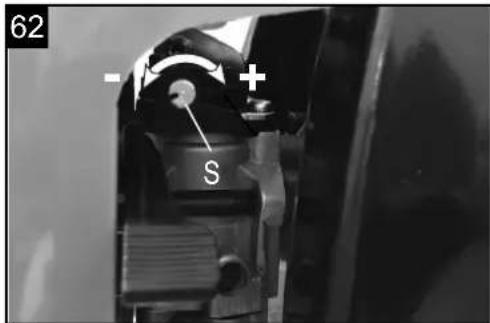
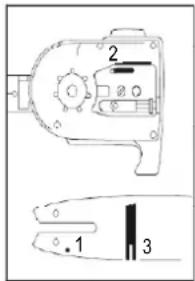
Setting the idle speed Fig. 50
If the cutting tool is still moving when the device is in idle, change the idle speed.
- Let the motor warm up for 3-5 minutes (not at high speed!).
- Turn the adjusting screw (S): clockwise
-- The idle speed will increase (+) anti-clockwise
-- The idle speed will decrease (-)
The idle speed is 3000 min ^-1 .
Contact the manufacturer if the cutting tool still continues to move in idle. Do not continue working with the tool!
The user is responsible for all damages caused by non-compliance with instructions in this manual. This also applies to non-authorized modifications of the tool, use of non-authorized spare parts, accessories, working tools, unrelated and not intended use, secondary damages due to use of faulty components.
Wear Parts
Even when used in the intended way, some components are subject to normal wear. They have to be replaced depending on the kind of duration of usage.
These parts include, among others, the cutting tool and the retaining disk.
⚠ Warning!
Use only original manufacturer's replacement parts, accessories and attachments. Failure to do so can cause poor performance, possible injury and may void your warranty.
Important hint in case of sending the equipment to a service station:
Due to security reasons please see to it that the equipment is sent back free of oil and gas!
Ordering replacement parts
Please quote the following data when ordering replacement parts:
- Type of machine
• Article number of the machine
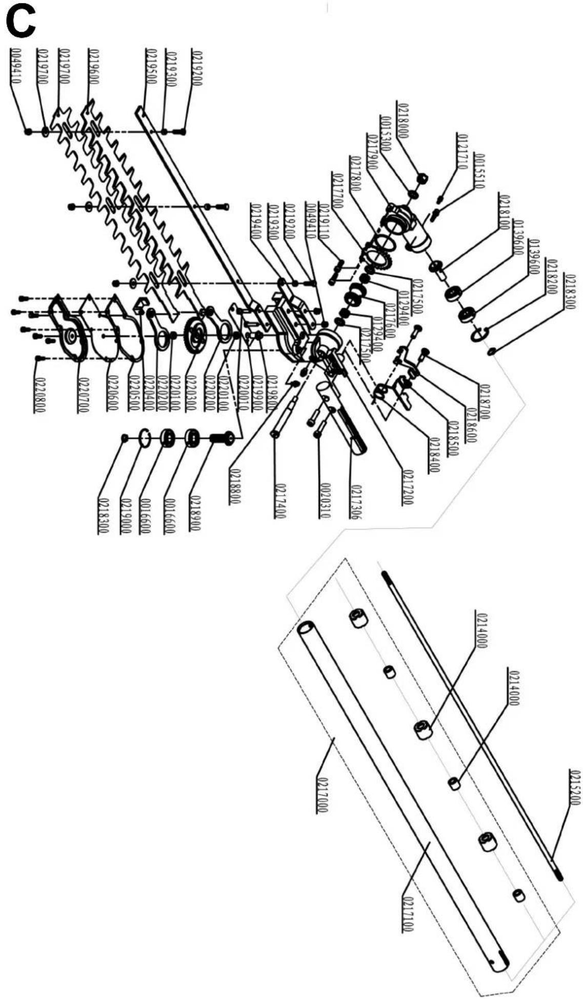
Replacement parts / accessories:
For the cutting equipment listed here, you can always use the safety guards provided with the unit.
Grass trimmer/brush cutter:
Spool with ∅ 450 7910700707
Blade with 3 teeth ∅ 255 x 1,4 7910700702
Transport guard for blade 3 teeth 3904801065
Blade with 4 teeth ∅ 255 x 1,5 7910700705
Transport guard for blade 4 teeth 3904801066
Blade with 8 teeth ∅ 255 x 1,5 7910700711
Transport guard for blade 8 teeth 3904801066
Safety shield for grass trimmer 3904803034
Pole pruner:
Saw chain Oregon 91PJ040X 7910700704
Guide rail Oregon 100SDEA318 3904801037
Transport guard for chain 3904801039
Extension for pole pruner 7910700710
Hedge trimmer:
Blade for hedge trimmer 400 mm 7910700703
Transport guard for blade 400 mm 3904801043
11. Storage
Cleaning
- Keep handles free of oil, so you always have a secure hold.
- Clean the equipment as required with a damp cloth and, if necessary, mild washing up liquid.
⚠️ Important!
• Always pull out the spark boot plug each time before carrying out any cleaning.
- Never immerse the equipment in water or other liquids in order to clean it.
- Store the petrol multi garden tool in a safe and dry place out of the reach of children.
Storage
Important: Never put the equipment into storage for longer than 30 days without carrying out the following steps.
Storing the equipment
If you intend to store the equipment for longer than 30 days, the equipment must be prepared accordingly. Otherwise the fuel still remaining in the carburetor will evaporate and leave a rubbery sediment. This can cause problems when starting up the equipment and may require expensive repairs.
1 Slowly remove the fuel tank cap to release any
pressure that may have formed in the tank. Carefully empty the tank. Only empty the tank outdoors or in well-ventilated rooms. Make sure that no fuel or chain oil is released into the soil (environmental protection). Use a suitable surface.
2 To remove the fuel from the carburetor, start the engine and let it run until the equipment stops.
3 Leave the engine to cool (approx. 5 minutes).
4 Remove the spark plug (see section 10 Change and clean the spark plug).
5 Add one teaspoon of 2-stroke engine oil into the combustion chamber. Slowly pull the starter cord several times to apply a layer of oil to all internal components. Fit the spark plug again.
Note: Store the equipment in a dry place and far away from possible ignition sources such as an oven, a gas fired hot water boiler, a gas fired dryer, etc.
Putting the equipment back into operation
1 Remove the spark plug (see section 10 Change and clean the spark plug).
2 Quickly tug on the starter cord to remove excess oil from the combustion chamber.
3 Clean the spark plug and check that the electrode gap is correct, or insert a new spark plug with the correct electrode gap.
4 Prepare the equipment for operation.
Transport
To transport the machine, empty the petrol tank as described in section 8 draining fuel. Clean coarse dirt off the equipment with a brush or hand brush.
Always attach the transport guard to all cutting tools. Fig. 1 (14a, 15a, 17a)
In order to prevent damage and injury, secure the tool against tipping over and sliding when transporting it in vehicles.
12. Disposal and recycling
The equipment is supplied in packaging to prevent it from being damaged in transit. The raw materials in this packaging can be reused or recycled. The equipment and its accessories are made of various types of material, such as metal and plastic. Defective components must be disposed of as special waste. Ask your dealer or your local council.
13. Troubleshooting
The table below contains a list of fault symptoms and explains what you can do to remedy the problem if your equipment fails to work properly. If the problem still persists after working through the list, please contact your nearest service workshop.
| Fault Possible cause Remedy | ||
| Machine does not start. | Air filter is contaminated.Fuel filter is blocked.Lack of fuel supply.Fault in the fuel line.Starting device is faulty.Engine stalled.Spark plug cap not attached.No spark.Engine faulty.Carburetor faulty | Clean/replace the air filter.Clean or renew the fuel filter.Re-fuel.Check the fuel line for kinks or damage.Contact the service centre.Remove the spark plug, clean and dry it; then pull the starter rope several times; re-fix the spark plug.Check the correct position of the spark plug cap.Clean the spark plug or replace it, if applicable.Check the ignition cable for damage.Contact the service centre.Contact the service centre. |
| Machine starts but stops again. | Wrong carburetor setting (idle speed). | Contact the service centre. |
| Engine starts but the cutting tool stops. | Cutting tool blocked.Internal fault (drive shaft, gearbox).Clutch faulty. | Turn off engine and remove object.Contact the service centre.Contact the service centre. |
| Machine works with interruptions (sputtering). | Carburetor set up incorrectly.Spark plug is sooty.On/off switch faulty. | Contact the service centre.Clean the spark plug or replace it.Contact the service centre. |
| Smoke is generated. | Wrong fuel mix.Carburetor set up incorrectly. | Use two-stroke mixture at a ratio of 40:1.Contact the service centre. |
| Machine does not work at full power. | Machine is overloaded.Air filter is contaminated.Carburetor set up incorrectly.Silencer is blocked. | Do not use force during mowing/trimming.Clean the air filter or replace it.Contact the service centre.Check the exhaust. |
| Brush cutter does not work at full power. | Blades are blunt or damaged.Cut material is too high (machine overload). | Sharpen or replace blades.Cut the grass in phases. |
| Grass trimmer does not work at full power. | Cutting line too short or damaged.Machine is overloaded because the grass is too high. | Feed more cutting line through or replace it.Cut the grass in phases. |
| Cutting line cannot be fed through. | Spool empty. Replace spool. | |
| Pole saw does not saw, it plucks or vibrates. | Chain tension too high.Chain blunt.Chain attached incorrectly.Chain worn. | Check and reset chain tension.Have the chain sharpened or replace it.Re-attach the chain.Replace the chain. |
| Saw chain becomes hot or saw chain lubrication does not work. | No oil in the tank.Oil line blocked.Chain tension too high.Chain blunt. | Refill oil.Clean the oil line.Set the chain tension.Have the chain sharpened or replace it. |
Table des matières: Page:
Günzburger Straße 69
D-89335 Ichenhausen
CHER CLIENT,
Günzburger Straße 69
D-89335 Ichenhausen
EGREGIO CLIENTE,
Günzburger Straße 69
D-89335 Ichenhausen
ESTIMADO CLIENTE,
D
E
| CE - KonformitätserklärungCE - Declaration of ConformityCE - Déclaration de conformité | Originalkonformitätserklärung |  | ||||
| scheppach Fabrikation von Holzbearbeitungsmaschinen GmbH • Günzburger Str. 69 • 89335 Ichenhausen / Germany | ||||||
| DE | erklärt folgende Konformität gemäß EU-Richtlinie und Normen für den Artikel | PL | deklaruje, ze produkt jest zgodny z nastepujacymi dyrektywami UE i normami | |||
| GB | hereby declares the following conformity under the EU Directive and standards for the following article | LT | pareiškia, taip atitiktis pagal ES direktyvos ir standartai šj straips-nj | |||
| FR | déclare la conformité suivante selon la directive UE et les normes pour l'article | HU | az EU-irányelv és a vonatkozó szabványok szerinti következo megfeleloségi nyilatkozatot teszi a termékre | |||
| IT | dichiara la seguente conformità secondo le direttive e le normative UE per l'articolo | SI | izjavlja sledeco skladnost z EU-direktivo in normami za artikel | |||
| ES | declara la conformidad siguiente según la directiva la UE y las normas para el articulo | CZ | prohlašuje následující shodu podle smernice EU a norem pro výrobek | |||
| PT | declara o seguinte conformidade com a Directiva da UE e as normas para o seguinte artigo | SK | prehlasuje nasledujúcu zhodu podla smernice EU a noriem pre výrobok | |||
| DK | erklærer hermed, at følgende produkt er i overensstemmelse med nedenstäende EUdirektiver og standarder | HR | ovime izjavljuje da postoji sukladnost prema EU-smjernica i nor-mama za sljedece artikle | |||
| NL | verklaart hierbij dat het volgende artikel voldoet aan de daarop betrekking hebbende EG-richtlijnen en normen | RS | potvrđuje sledeću usklađenost prema smernicama EZ i normama za artikal | |||
| FI | vakuuttaa täten, että seuraava tuote täyttää ala esitetyt EU-direktiivit ja standardit | RO | declară următoarea conformitate corespunzător directivelor și normelor UE pentru articolul | |||
| SE | försäkrar härmed följande överensstämmelse enligt EU-direktiv och standarder för följande artikeln | BG | декларира съответното съответствие съгласно Дирек-тива на ЕС и норми за артикул | |||
| Marke / Brand: SCHEPPACHArt.-Bezeichnung / Article name: BENZIN MULTIFUNKTIONSGERÄTPETROL MULTI GARDEN TOOLMACHINE THERMIQUE MULTI-OUTILS POUR LE JARDINTyp / Type: MTC53-5PArt.-Nr. / Art. no.: 5804805903Serien Nr. / Serial. No.: 0169-01001 - 0169-03001 | ||||||
| 2014/29/EU | 2004/22/EC | 89/686/EC_96/58/EC | X 2000/14/EC_2005/88/EC | |||
| 2014/35/EU | 2014/68/EU | 90/396/EC | Annex V | |||
| X | 2014/30/EU | 2011/65/EU* | Annex VINoise: MFH5200-4P: measured L_WA = 114,9 dB(A);guaranteed L_WA = 117 dB(A)Notified Body: SGS-CSTC Standards Technical Services Co., Ltd.Notified Body No.: 0890 | |||
| X 2006/42/EC | ||||||
| x | Annex IVNotified Body: SGS-CSTC Standards Technical Services Co., Ltd.Notified Body No.: 0890Certificate No.: | X 2010/26/EC | ||||
| Emission. No: e11*97/68SA*2012/46*3184*01 | ||||||
| Standard references: | ||||||
| EN ISO 10517 : 2009+A:2013; EN ISO 11806-1:2011 ; EN ISO 11680-1:2011;EN ISO 15503-1:2009+A2:2015;EN ISO 14982 :2009 ; ISO 22868:2011, EN ISO 3744:1995 | ||||||
| Die alleinige Verantwortung für die Ausstellung dieser Konformitätserklärung trägt der Hersteller.This declaration of conformity is issued under the sole responsibility of the manufacturer.Le fabricant assume seul la responsabilité d'établir la présente déclaration de conformité. | ||||||
| Ichenhausen, den 23.04.2018Unterschrift / Markus Bindhammer / Technical Director | ||||||
| First CE: 2017Subject to change without notice | Documents registar: Stefan HartingerGünzburger Str. 69, D-89335 Ichenhausen | |||||
Garantie DE
Apparent defects must be notified within 8 days from the receipt of the goods. Otherwise, the buyer's rights of claim due to such defects are invalidated. We guarantee for our machines in case of proper treatment for the time of the statutory warranty period from delivery in such a way that we replace any machine part free of charge which provably becomes unusable due to faulty material or defects of fabrication within such period of time. With respect to parts not manufactured by us
we only warrant insofar as we are entitled to warranty claims against the upstream suppliers. The costs for the installation of the new parts shall be borne by the buyer. The cancellation of sale or the reduction of purchase price as well as any other claims for damages shall be excluded. The saw blade is a consumable item and explicitly excluded from any warranty.