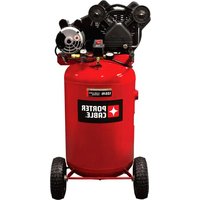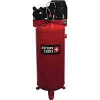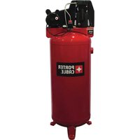
PXCMLC3706056 - Compressor Porter-Cable - Free user manual and instructions
Find the device manual for free PXCMLC3706056 Porter-Cable in PDF.


User questions about PXCMLC3706056 Porter-Cable
0 question about this device. Answer the ones you know or ask your own.
Ask a new question about this device
Download the instructions for your Compressor in PDF format for free! Find your manual PXCMLC3706056 - Porter-Cable and take your electronic device back in hand. On this page are published all the documents necessary for the use of your device. PXCMLC3706056 by Porter-Cable.
USER MANUAL PXCMLC3706056 Porter-Cable
Single Stage, Belt Drive, Electric Air Compressors
natural_image
Technical line drawing of a cylindrical industrial pressure vessel with internal components and mounting feet (no text or symbols)TABLE OF CONTENTS
SAFETY GUIDELINES 3-6
SPECIFICATION CHART 6
OVERVIEW 6
Basic Air Compressor Components......6
ASSEMBLY....7
Assembling the Compressor ....7
TYPICAL INSTALLATION....8-9
COMPRESSOR CONTROLS....10
ELECTRICAL POWER REQUIREMENTS .....11
Electrical Wiring 11
Main Power Panel....11
Main Power Disconnect Switch....11
Low Voltage Problems....11
Grounding Instructions ......11
MOTOR RESET SWITCH 12
OPERATING INSTRUCTIONS 12-14
Break-in of the Pump....12
Daily Startup 14
Shutdown....14
MAINTENANCE....15-18
Draining the Tank....15
Checking the Oil 15
Changing the Oil 15
Belt Tension 16
Pulley Alignment....17
Cleaning the Air Filter 18
Checking the Relief Valve 18
Testing for Leaks....18
Storage 18
SERVICE INTERVAL....18
TROUBLESHOOTING CHART 19-20
PARTS DRAWINGS AND PARTS LISTS.....21-25
WARRANTY 26-28
GLOSSARY OF TERMS 29
PARTS AND SERVICE....30
TABLE DES MATIÈRES
CONSIGNES DE SÉCURITÉ ...... 3, 31-33
TABLEAU DES SPÉCIFICATIONS ....33
VUE D'ENSEMBLE....34
The following information relates to protecting YOUR SAFETY and PREVENTING EQUIPMENT PROBLEMS. To help you recognize this information, we use the following symbols. Please read the manual and pay attention to these sections.

DANGER
Indicates an imminently hazardous situation which, if not avoided, will result in death or serious injury.

WARNING
Indicates a potentially hazardous situation which, if not avoided, could result in death or serious injury.

CAUTION
Indicates a potentially hazardous situation which, if not avoided, may result in minor or moderate injury.
CONSIGNES DE SÉCURITÉ
Read and understand all safety precautions in this manual before operating. Failure to comply with instructions in this manual could result in personal injury, property damage, and/or voiding of your warranty. The manufacturer WILL NOT be liable for any damage because of failure to follow these instructions.

- RISK OF FIRE OR EXPLOSION. Never spray flammable liquids in a confined
area. It is normal for the motor and pressure switch to produce sparks while operating. If sparks come into contact with vapors from gasoline or other solvents, they may ignite, causing fire or explosion. Always operate the compressor in a well-ventilated area. Do not smoke while spraying. Do not spray where sparks or flame are present. Keep compressor as far from spray area as possible.

- RISK OF BURSTING. Do not weld, drill or modify the air tank of this compressor. Welding or modifications on the air
compressor tank can severely impair tank strength and cause an extremely hazardous condition. Welding or modifying the tank in any manner will void the warranty.

- RISK OF ELECTRICAL SHOCK. Never use an electric air compressor outdoors when it is raining or on a wet surface,
as it may cause an electric shock.

- RISK OF INJURY. This unit starts automatically. ALWAYS shut off the main power disconnect, and bleed all
pressure from the system before servicing the compressor, and when the compressor is not in use. Do not use the unit with the shrouds or belt guard removed. Serious injury could occur from contact with moving parts.

- RISK OF BURSTING. Check the manufacturer's maximum pressure rating for air tools and accessories. Compressor outlet
pressure must be regulated so as to never exceed the maximum pressure rating of the tool. Relieve all pressure through the hose before attaching or removing accessories.

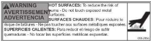
- RISK OF BURNS. High temperatures are generated by the pump and manifold. To prevent burns or other injuries,
DO NOT touch the pump, manifold or transfer tube while the pump is running. Allow them to cool before handling or servicing. Keep children away from the compressor at all times.

- RISK TO BREATHING. Be certain to read all labels when you are spraying paints or toxic materials, and follow the safety
instructions. Use a respirator mask if there is a chance of inhaling anything you are spraying. Read all instructions and be sure that your respirator mask will protect you. Never directly inhale the compressed air produced by a compressor. It is not suitable for breathing purposes.

- RISK OF EYE INJURY.
Always wear ANSI Z87.1 approved safety goggles when
using an air compressor. Never point any nozzle or sprayer toward a person or any part of the body. Equipment can cause serious injury if the spray penetrates the skin.

- RISK OF BURSTING. Do not adjust the relief valve for any reason. Doing so voids all warranties. The relief valve has
been pre-set at the factory for the maximum pressure of this unit. Personal injury and /or property damage may result if the relief valve is tampered with.

- RISK OF BURSTING.Do not use plastic or pvc pipe for compressed air. Use only gavanized steel pipe and fittings ssed air distribution lines.

- RISK OF BURSTING. Failure to properly drain condensed water from air tank, causing rust and thinning of the steel air
tank. Drain air tank daily or after each use. If air tank develops a leak, replace it
immediately with a new air tank or replace the entire compressor.
- RISK TO HEARING. Always wear hearing protection when using an air compressor. Failure
to do so may result in hearing loss.
NOTE: ELECTRICAL WIRING. Refer to the air compressor's serial label for the unit's voltage and amperage requirements. Ensure that all wiring is done by a licensed electrician, in accordance with the National Electrical code.

WARNING: CONTAINS
LEAD. May be harmful if eaten or chewed. May generate dust
containing lead. Wash hands after use. Keep out of reach of children.

WARNING: This product can expose you to chemicals including Lead, which is known to the State of California to cause cancer and birth defects or other reproductive harm. For more information go to www.P65Warnings.ca.gov.
⚠️ DANGER

RISK OF BURSTING.
Air Tank: On February 26, 2002, the U.S. Consumer Product Safety Commission published Release # 02-108 concerning air compressor tank safety:
Air compressor receiver tanks do not have an infinite life. Tank life is dependent upon several factors, some of which include operating conditions, ambient conditions, proper installations, field modifications, and the level of maintenance. The exact effect of these factors on air receiver life is difficult to predict.
If proper maintenance procedures are not followed, internal corrosion to the inner wall of the air receiver tank can cause the air tank to unexpectedly rupture allowing pressurized air to suddenly and forcefully escape, posing risk of injury to consumers.
Your compressor air tank must be removed from service by the end of the year shown on your tank warning label.
The following conditions could lead to a weakening of the air tank, and result in a violent air tank explosion:
WHAT CAN HAPPEN HOW TO PREVENT IT
- Failure to properly drain condensed water from air tank, causing rust and thinning of the steel air tank.
- Modifications or attempted repairs to the air tank.
-
Unauthorized modifications to the safety valve, or any other components which control air tank pressure.
-
Drain air tank daily or after each use. If air tank develops a leak, replace it immediately with a new air tank or replace the entire compressor.
- Never drill into, weld or make any modifications to the air tank or its attachments. Never attempt to repair a damaged or leaking air tank. Replace with a new air tank.
- The air tank is designed to withstand specific operating pressures. Never make adjustments or parts substitutions to alter the factory set operating pressures.
WARNING
- Drain the moisture from the tank on a daily basis. A clean, dry tank will help prevent corrosion.
-
Pull the pressure relief valve ring daily to ensure that the valve is functioning properly, and to clear the valve of any possible obstructions.
-
To provide proper ventilation for cooling, the compressor must be kept a minimum of 12 inches (31 cm) from the nearest wall, in a well-ventilated area.
- To prevent damage to tank and compressor on stationary models, the tank must be shimmed so the pump base is level within 1/8" to distribute oil properly. All feet must be supported, shimming where necessary, prior to attaching to the floor. Fasten all feet to floor. We also recommend the use of vibration pads (094-0137) under tank feet.
- Fasten the compressor down securely if transporting is necessary. Pressure must be released from the tank before transporting.
- Protect the air hose from damage and puncture. Inspect them weekly for weak or worn spots, and replace if necessary.
- To reduce the risk of electric shock, do not expose to rain. Store indoors.
SPECIFICATION CHART
| MODEL NO. | RUNNING H.P. | TANK CAPACITY GALLONS | VOLTAGE/AMPS/PHASE | KICK-IN PRESSURE | KICK-OUT PRESSURE |
| PXCMLC3706056 3.7 | 60 (227, 1) | 240/15/1 | 105 (7,24 bar) | 135 (9,31 bar) |
BASIC AIR COMPRESSOR COMPONENTS
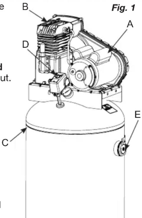
The basic components of the air compressor are the electric motor, pump, pressure switch and tank (see Fig. 1). The tank may be vertical or horizontal, varying in size and capacity.
The electric motor (see A) powers the pump. The electric motor is equipped with an overload protector to help prevent possible motor burnout. If the motor becomes overheated, the overload protector will shut it down. Should this occur, allow the motor to cool for 10-15 minutes, then press (never force) the motor reset switch to restart the motor.
The pump (see B) compresses the air and discharges it into the tank.
The tank (see C) stores the compressed air.
The pressure switch (see D) shuts down the motor and relieves air pressure in the pump and transfer tube when the air pressure in the tank reaches the kick-out pressure. As compressed air is used and the pressure level in the tank drops to the kick-in pressure, the pressure switch restarts the motor automatically, without warning and the pump resumes compressing air.
text_image
Fig. 1 A B D C E I ut.NOTE: See pages 8 & 9 for typical installation of the 60 gallon model.
The air line outlet (see E). Connect 1/4" NPT air hose to this outlet.
ASSEMBLING THE COMPRESSOR
- Unpack the air compressor. Inspect the unit for damage. If the unit has been damaged in transit, contact the carrier and complete a damage claim. Do this immediately because there are time limitations to damage claims.
The carton should contain:
-
air compressor
• operator and parts manuals -
Check the compressor's serial label to ensure that you have received the model ordered, and that it has the required pressure rating for its intended use.
- Locate the compressor according to the following guidelines:
a. For optimum performance, locate the compressor close to the power panel, as specified in ELECTRICAL POWER REQUIREMENTS, and as close as possible to the place where the air will be used. This ensures maximum power to the compressor and maximum air pressure to the tool. If both of these conditions cannot be met, it is better to locate the compressor close to the power panel, and use a longer air hose to reach the usage area.
b. The flywheel side of the compressor must be at least 12 inches (31 cm) from any wall or obstruction, in a clean, well-ventilated area, to ensure sufficient air flow and cooling.
c. In cold climates, locate the compressors in a heated building when not in use. This will reduce problems with lubrication, motor starting and freezing of water condensation.
d. Remove the compressor from the shipping pallet and place it on the floor or a hard, level surface. The compressor must be level to ensure proper lubrication of the pump and good drainage of the moisture in the tank.
WARNING
Risk of injury: The shipping pallet is not designed as a base for compressor. Operating the compressor while it is on the pallet will ranty.
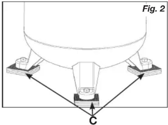
e. To prevent damage to tank and pump, the tank must be shimmed so the pump is level within 1/8" per lineal foot maximum to distribute oil properly. Fasten to floor and NEVER force tank feet to floor without shims when tightening. We also recommend the use of vibration pads (094-0137) under tank feet (C).
- Connect an air hose (not included) to the compressor.
text_image
Fig. 2 C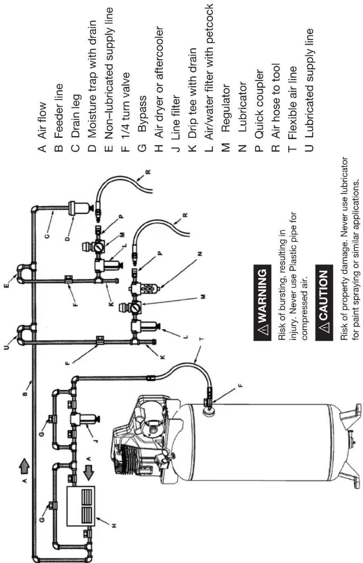
text_image
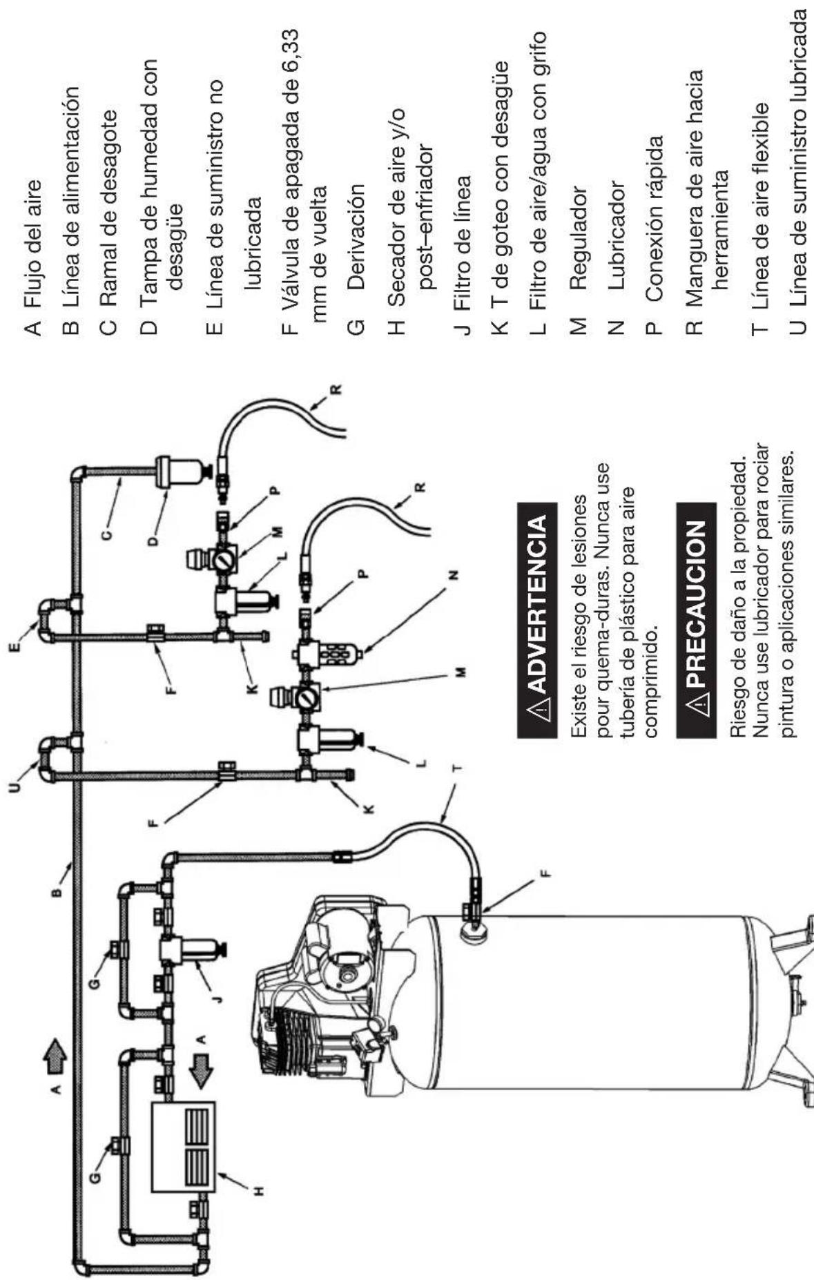
A Air flow B Feeder line C Drain leg D Moisture trap with drain E Non-lubricated supply line F 1/4 turn valve G Bypass H Air dryer or aftercooler J Line filter K Drip tee with drain L Air/water filter with petcock M Regulator N Lubricator P Quick coupler R Air hose to tool T Flexible air line U Lubricated supply line WARNING Risk of bursting, resulting in injury. Never use Plastic pipe for compressed air. CAUTION Risk of property damage. Never use lubricator for paint spraying or similar applications.TYPICAL INSTALLATION
AIR DRYERS AND AFTER COOLERS
An air dryer or aftercooler is installed directly in the air line.
MOISTURE REMOVAL AND AIR FILTRATION
As the air cools, moisture will condense in the lines. This moisture must be removed before it reaches the tool being used. To remove this moisture, run the main air line downhill to a moisture trap and drain. Air/water filters should also be installed in the positions shown.
AIR PRESSURE REGULATION
Install an air regulator in the drop line for each tool, to regulate air pressure to that tool. Never exceed the maximum pressure rating of the tool.
AIR LUBRICATION
Install an air lubricator only for those tools requiring lubrication. Do not use a lubricator for paint spraying or similar applications. The oil will contaminate the paint and ruin the job.
SHUT-OFF VALVES
Install shut-off valves in each drop line, to isolate the tool and its accessories for servicing. You can also install a bypass line around an accessory.
COMPRESSOR CONTROLS
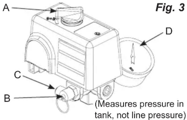
Refer to Fig. 3.
Pressure switch (see A)
This switch turns on the compressor. It is operated manually, but when in the ON position, it allows the compressor to start up or shut down automatically, without warning, upon air demand. ALWAYS set this switch to OFF when the compressor is not being used.

WARNING
For your safety, tank pressure is preset within the switch
and must never be tampered with.
This switch must not be adjusted by the operator; doing so will void the warranty. The pressure switch controls the level of air pressure in the tank by automatically starting and stopping the motor, as required to maintain the factory preset pressure level.
The pressure switch also automatically bleeds pressure from the pump head when the pump stops. This feature eliminates back pressure in the pump, ensuring easier starting.
Tank Safety Valve (see B)
Used to allow tank pressure to escape into the atmosphere. If the pressure switch does not shut off the compressor at it's “cut-out” pressure setting, the safety valve will protect against high pressure by releasing tank pressure at it's factory set pressure (slightly higher than the pressure switch “cut-out” setting). To operate manually, pull the ring on the valve to relieve air pressure in the tank.
Pressure Release Valve (see C)
The pressure release valve (located on the bottom of the pressure switch), is designed to release compressed air from the compressor head and outlet tube when the compressor reaches “cut-out” or is shut off. The pressure valve allows the motor to restart freely. When the motor stops running, air will be heard escaping from this valve for a few seconds. No air should be heard leaking when the motor is running or after brief release after reaching “cut-out” pressure.
Tank Pressure Gauge (see D)
This gauge measures the pressure level of the air stored in the tank. It is not adjustable by the operator, and does not indicate line pressure.
text_image
Fig. 3 A D C B (Measures pressure in tank, not line pressure)ELECTRICAL POWER REQUIREMENTS

WARNING
Risk of electrical shock. Improper electrical grounding electrical shock. The wiring should be done by a qualified
ELECTRICAL WIRING
Refer to the air compressor's serial label for the unit's voltage and amperage requirements. Ensure that all wiring is done by a licensed electrician, in accordance with the National Electrical Code..
MAIN POWER PANEL
For best performance and reliable starting, the air compressor must be installed on a dedicated circuit, as close as possible to the electrical power panel. Provide circuit breaker or fuse protection at your main power panel. Use time delay fuses on the circuit, because the compressor will momentarily draw several times its specified amperage when first started.
NOTE: A circuit breaker is recommended. If the air compressor is connected to a circuit protected by a fuse, use dual element time delay fuses (Buss Fusetron type "T" only).
MAIN POWER DISCONNECT SWITCH
Install a main power disconnect switch in the line from the panel to the compressor. The main power disconnect switch must be located near the compressor, for ease of use and safety. When turned OFF, the main power disconnect switch shuts off all power to the compressor. When it is turned ON, the compressor will start and stop automatically, controlled by the pressure switch.
LOW VOLTAGE PROBLEMS
Low voltage will cause difficult starting or an overload. Low voltage can be caused by a low supply voltage from the local power company, other equipment running on the same line, or inadequate wiring. If any other electrical devices are drawing from the compressor's circuit, it may fail to start.
Low voltage to the compressor can be caused by a supply wire of insufficient gauge for the distance between the compressor and the power source. The longer the distance, the larger the wire gauge (lower the number) must be, to overcome the inherent voltage loss caused by the wire resistance. Refer to the National Electrical Code to determine proper wire size for your circuit.
If the wiring is not adequate, the input voltage will drop by 20 to 40 volts at startup. Low voltage or an overloaded circuit can result in sluggish starting that causes the circuit breaker to trip, especially in cold conditions.
GROUNDING INSTRUCTIONS
This product must be connected to a grounded, metallic, permanent wiring system, or an equipment - grounding terminal or lead on the product.
MOTOR RESET SWITCH AND WIRING
WARNING
Ensure that all guards and shrouds are in place before
pressing the reset switch to restart the motor.
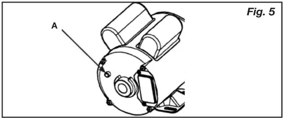
If the motor shuts down because of overload, wait 10–15 minutes so the motor can cool down, then press (NEVER force) the reset switch (see A) to restart the motor (see Fig. 5).
Note: On stationary models not supplied with a power cord, the electrical power must be wired into the pressure switch by a Licensed Electrician.
natural_image
Technical line drawing of a mechanical assembly with labeled component A, no readable text or symbols beyond labelOPERATING INSTRUCTIONS
BREAK-IN OF THE PUMP (Fig. 6)
- Make sure the power is connected at the power panel.
- Check the oil level in the pump (see "Checking the Oil" in the maintenance section).
- Open the petcock (see F).

WARNING
Escaping air and moisture can propel debris that injury. Wear safety goggles when opening petcock.
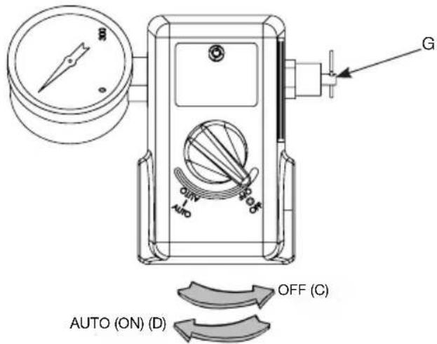
- Turn ON the main power disconnect switch. Turn the pressure switch to the AUTO position (see D). The motor should start. Allow the compressor to run for 30 minutes, to break in the internal parts.
NOTE: After about 30 minutes, if the unit does not operate properly, SHUT DOWN IMMEDIATELY, and contact a qualified service center. DO NOT return the unit to the store where it was purchased.
- Shut OFF the main power disconnect. Close the petcock (see E). Connect your air hose(s) to the tank outlet(s).
NOTE: As compressed air is used, the pressure switch will restart the motor automatically to supply more compressed air to the tank.
Fig. 6
text_image
G ON AFO OFF (C) AUTO (ON) (D)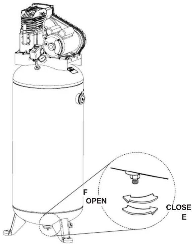
text_image
F OPEN CLOSE EOPERATING INSTRUCTIONS
DAILY START-UP (Fig. 6)
- Check the oil level in the pump (see "Checking the Oil" in the maintenance section).
- Make sure the main power disconnect switch is shut OFF.
- Close the tank petcock (see E).
- Turn ON the main power disconnect switch. Turn the pressure switch to the AUTO position (see D). The pump will start filling the tank with air. When the air pressure in the tank reaches the level preset at the factory, the pressure switch will turn off the electric motor. As air is used and the pressure level in the tank drops, the pressure switch will start the motor and the pump will begin refilling the tank.

WARNING
High temperatures are generated by the pump. To prevent burns or other injuries, DO NOT touch the pump or transfer tube while the pump is running. Allow it to cool before handling or servicing. Keep children away from the compressor at all times.
NOTE: If the unit does not operate properly, SHUT DOWN IMMEDIATELY, and contact a qualified service center.
SHUTDOWN (Fig. 6)
- Turn the pressure switch to the OFF position (see C).
- Shut OFF the main power disconnect switch.
- Reduce pressure in the tank through the outlet hose. You can also pull the tank safety valve ring (see G) and keep it open to relieve pressure in the tank.

WARNING
Escaping air and moisture can propel debris that injury. Wear safety goggles when opening petcock.
- Open the petcock (see F) to allow moisture to drain from the tank.
MAINTENANCE
MAINTENANCE
WARNING
To avoid personal injury, always shut off and unplug the compressor and relieve all air pressure from the system
before performing any service on the air compressor.
Regular maintenance will ensure trouble-free operation. Your electric powered air compressor represents high-quality engineering and construction; however, even high-quality machinery requires periodic maintenance. The items listed below should be inspected on a regular basis
DRAINING THE TANK (Fig. 6)

WARNING
Condensation will accumulate in the tank. To find of the tank from the inside, this moisture must be found at the end of every workday.

WARNING
Be sure to wear protective eyewear. Relieve the air pressure in the system and open the petcock on the bottom of the tank to drain.
CHECKING THE OIL
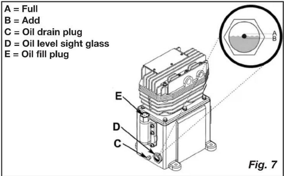
Check the level of oil in the pump with the sight glass. The pump oil level must be between A and B (See Fig. 7). Do not overfill or underfill.
NOTE: Use full synthetic, non-detergent air compressor oil.
CHANGING THE OIL
Remove the oil plug (C) (Fig. 7) and drain the oil until it slows to a drip, then close. Add oil to the pump by first removing the breather plug (E). Add oil until the level viewed through the sight glass (D) is between FULL (A) and ADD (B). Never overfill or underfill the pump.
NOTE: The compressor is pre-filled with synthetic oil. Use full synthetic, non-detergent air compressor oil.
text_image
A = Full B = Add C = Oil drain plug D = Oil level sight glass E = Oil fill plug Fig. 7MAINTENANCE
BELT TENSION AND PULLEY ALIGNMENT
WARNING
To avoid personal injury, always shut off and unplug the relieve all air pressure from the system before performing the air compressor.
NOTE: Drive belt tensioning and pulley alignment are done at the same time. They are discussed separately for clarity.
ADJUSTING DRIVE BELT TENSION
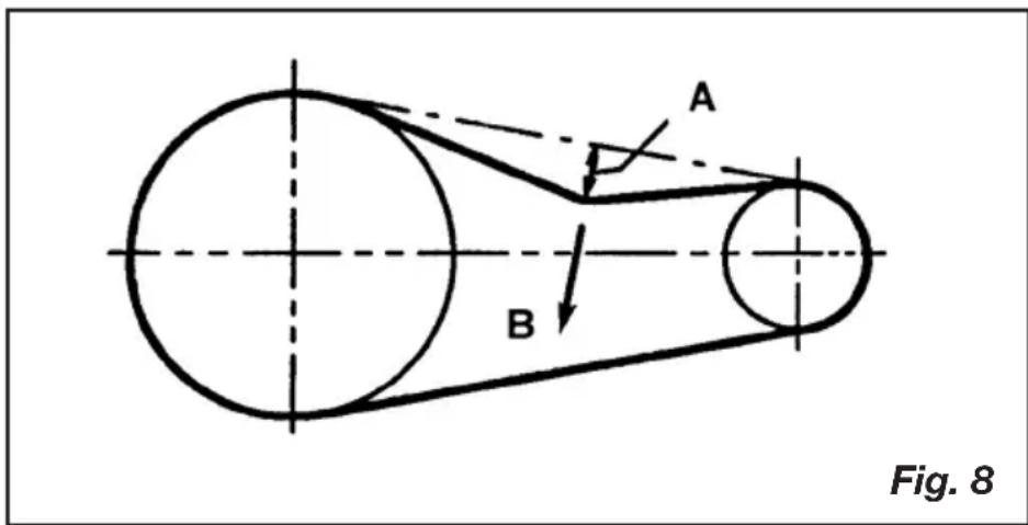
Proper belt tension and pulley alignment must be maintained for maximum drive efficiency and belt life. The correct tension exists if a deflection (see A) of 1/2" (13 mm) occurs by placing 5 lb (2.3 kg) of force (see B) midway between the motor pulley and the pump flywheel (See Fig. 8). This deflection can be adjusted by the following procedure. The pulley should be carefully aligned with the flywheel, and all setscrews should be kept tight.
- Remove the belt guard.
- Loosen the motor mounting bolts.
- Shift the motor to the point where the correct deflection exists.
- Retighten the motor mounting bolts.
- Check to ensure that the tension remained correct.
- Reinstall the belt guard. All moving parts must be guarded.
text_image
A B Fig. 8MAINTENANCE
PULLEY ALIGNMENT
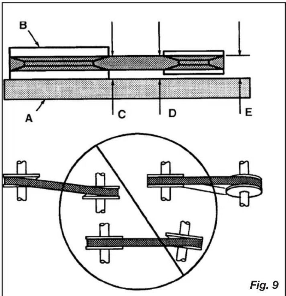
To check pulley alignment, remove the belt guard and place a straightedge (see A) against the pump flywheel (see B) (See Fig. 9). Measure and record the distance from the straightedge to the edge of the drive belt at point C. Then measure the distance from the straightedge to the edge of the drive belt again at points D and E. Both distances should be the same as at point C. If D or E are different from C, there is a misalignment which must be corrected before the compressor is run. To correct a pulley misalignment, use the following procedure.
- Remove the belt guard.
- Loosen the motor mounting bolts.
- Loosen the setscrew on the motor pulley.
- Align the motor pulley with the pump flywheel (C = D = E).
- Retighten the motor pulley setscrew.
- Adjust the proper belt tension.
- Retighten the motor mounting bolts.
- Reinstall the belt guard. All moving parts must be guarded.
text_image
B A C D E Fig. 917-ENG
MAINTENANCE
CLEANING THE AIR FILTER
A dirty air filter will reduce the compressor's performance and life. To avoid any internal contamination of the pump, the filter should be cleaned frequently, and replaced on a regular basis. Felt filters should be cleaned in warm, soapy water, rinsed, and allowed to air dry before reinstallation. Paper filters should be replaced when dirty. Do not allow the filter to become filled with dirt or paint. If the filter becomes filled with paint, it should be replaced. Direct exposure to dirty conditions or painting areas will void your warranty.
CHECKING THE RELIEF VALVE
Pull the relief valve daily to ensure that it is operating properly and to clear the valve of any possible obstructions.
TESTING FOR LEAKS
Check that all connections are tight. A small leak in any of the hoses, transfer tubes, or pipe connections will substantially reduce the performance of your air compressor. If you suspect a leak, spray a small amount of soapy water around the area of the suspected leak with a spray bottle. If bubbles appear, repair or replace the faulty component. Do not overtighten any connections.
STORAGE
Before storing the compressor for a prolonged period, use an air blow gun to clean all dust and debris from the compressor. Disconnect the power cord and coil it up. Pull the pressure relief valve to release all pressure from the tank. Drain all moisture from the tank. Clean the filter element and filter housing; replace the element if necessary. Drain the oil from the pump crankcase and replace it with new oil. Cover the entire unit to protect it from moisture and dust.
SERVICE INTERVAL
| Perform the following maintenance at the intervals indicated below. | Daily or after each use | Monthly or Every 50 Hours | 1 Year or 200 Hours | After first 8 hours and then every 500 operating hours |
| Inspect air filters (clean or replace as necessary) | ● | |||
| Check pump oil level | ● | |||
| Change pump oil (Use full synthetic, non-detergent air compressor oil.) | ● | |||
| Operate the tank safety valve | ● | |||
| Check belt tension | ● | |||
| Drain tank | ● | |||
| Check and tighten all bolts (do not over tighten) | ● |
TROUBLESHOOTING
Note: Troubleshooting problems may have similar causes and solutions.
| PROBLEM POSSIBLE | CAUSE SOLUTION | |
| Excessive current draw trips circuit breaker of motor reset switch | Low voltage/motor overload | Check that power supply is adequate and that compressor is on a dedicated circuit. If using extension cord, try using without. If compressor is connected to a circuit protected by a fuse, use dual element time delay fuses (Buss Fusetron type “T” only). |
| Drive belt too tight Readjust | st belt tension | |
| Restricted air passages In | spect and replace transfer tubes or check valve, as required. | |
| Compressor stalls Low voltage motor Furnish adequate power. | ||
| Low discharge pressure | Air leaks Tighten or replace | leaking fittings or connections. Do not overtighten. |
| Leaking valves Contact authorized service center. | ||
| Restricted air intake Clean or replace air filter element(s). | ||
| Blown gaskets Contact authorized service center. | ||
| Worn piston rings or cylinder | Contact authorized service center. | |
| Compressor pump knocking | Loose engine pulley or compressor flywheel | Retighten pulley and flywheel. Check alignment. |
| Low oil level in pump crankcase | Keep oil at proper level at all times. | |
| Excess carbon on valves or top of piston | Contact authorized service center. | |
TROUBLESHOOTING
| PROBLEM POSSIBLE | CAUSE SOLUTION | |
| Oil in discharge air Worn | piston rings or cylinder | Contact authorized service center. |
| Restricted air intake Clean | or replace the air filter element(s). | |
| Oil level too high Reduce to proper level. | ||
| Overheating Poor ventilation | tion Relocate compressor to | an area with cool, dry, well circulated air, at least 12 in. from nearest wall. |
| Dirty cooling surfaces Clean | an all cooling surfaces thoroughly. | |
| Restricted air passages Re | replace transfer tubes and/or unloader. | |
| Excessive belt wear Pulley out of alignment Realign | pulley with compressor flywheel. | |
| Improper belt tension Readjust. | ||
| Pulley wobbles Replace the pulley and check for a damaged crankshaft or flywheel. | ||
| Compressor won't start in cold temperatures | Too much back pressure in tank | Open petcock when starting motor. |
| 40W oil in crankcase Use | full synthetic, non-detergent air compressor oil. | |
| Compressor too cold Move | compressor to a warmer location. | |
PARTS DRAWING
text_image
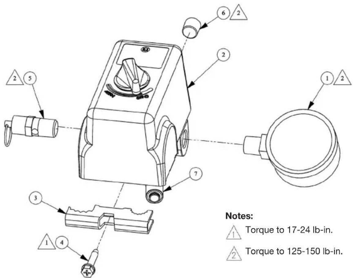
Notes: 1 Torque to 17-24 lb-in. 2 Torque to 125-150 lb-in.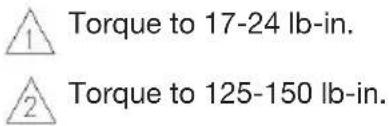
text_image
Torque to 17-24 lb-in. Torque to 125-150 lb-in.PARTS LIST
Item Part No Qty Description
1 032-0144 1 Gauge, 300# 1/4" bottom connect
2 034-0226 1 Switch, pressure includes items 3-4 & 7
3 071-0033 1 Strain relief
4 061-0216 1 Screw
5 136-0005 1 Valve, ASME
6 062-0035 1 Plug, 1/4"
7 136-0090 1 Valve, bleeder
text_image
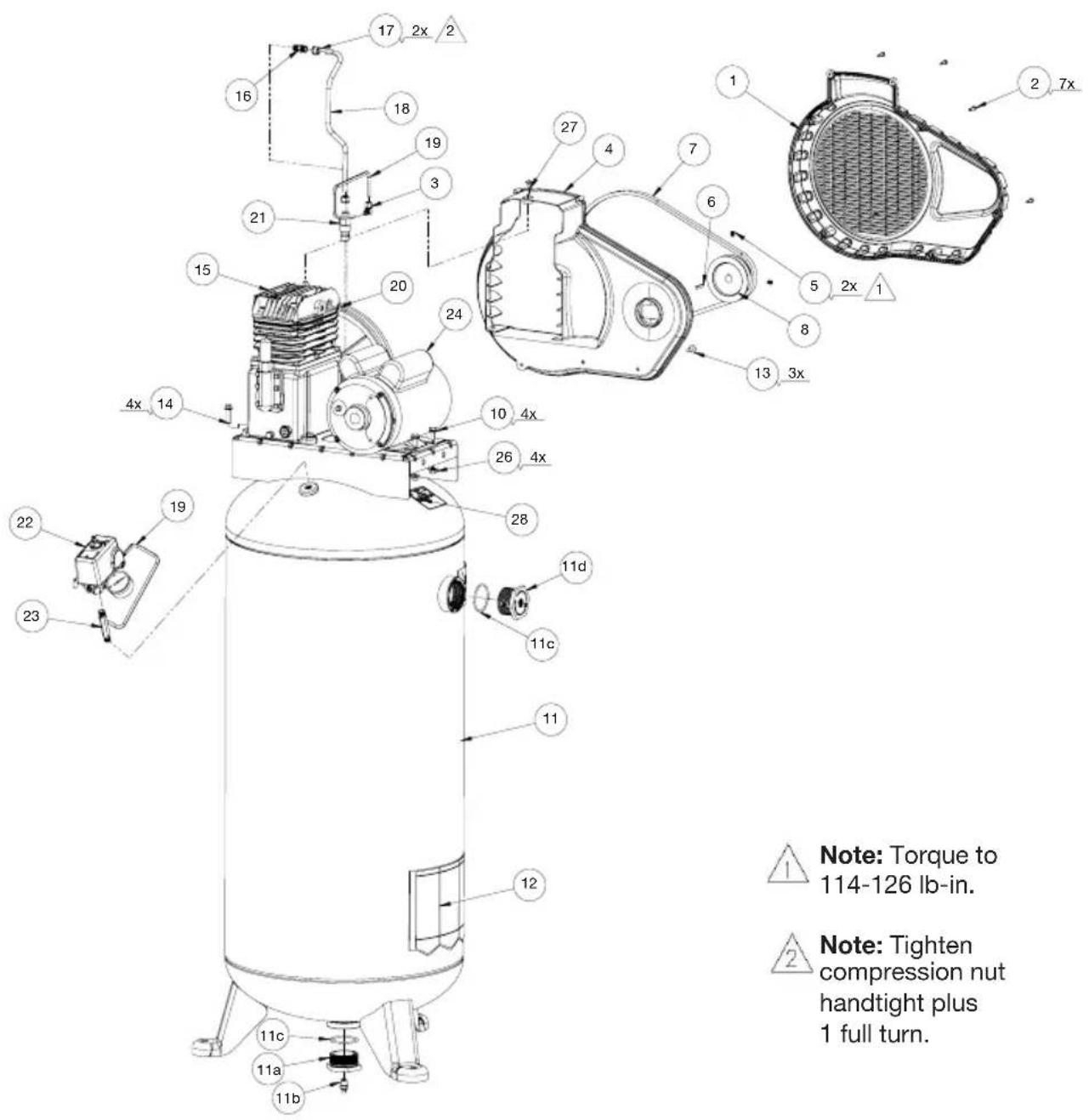
17 2x 2 16 18 19 3 21 15 20 24 27 4 7 6 1 2 7x 5 2x 1 8 13 3x 4x 14 10 4x 26 4x 28 11d 11c 11 12 11c 11a 11b 22 19 23 Note: Torque to 114-126 lb-in. Note: Tighten compression nut handtight plus 1 full turn.
Note: Torque to 114-126 lb-in.

Note: Tighten compression nut handtight plus 1 full turn.
PARTS LIST
Item Part No Qty Description
1 125-0256 1 Beltguard (outer).
2 061-0152 7 Plastite screw
3 064-0003 1 Elbow, 90°
4 125-0257 1 Beltguard (inner)
5 061-0238 2 Setscrew, 5/16-18 x .38
6 146-0016 1 Key
7 007-0079 1 V-Belt, A44
8 006-0173 1 Pulley
9 026-0233 1 Cord, interconnect
10 059-0474 4 Bolt, 3/4" whiz lock hex
11b 072-0006 1 Petcock
11c 513-0001 2 O-Ring 2"
12 098-3870 1 Label, warning
13 059-0475 3 Screw, 1/4-20
14 059-0473 4 Bolt, .315-18 x 1.25"
16 068-0092 1 Connector
17 058-0007 2 Nut, 3/8" O.D. tube
18 S145-0730 1 Tube, transfer
19 S145-0731 1 Tube, bleeder
20 062-0001 1 Plug, 1/8" x 5/16"
21 031-0037 1 Check Valve, 1/2" x 3/8"
22 See page 21 1 Switch assembly
23 065-0004 1 Nipple, 1/4"-18 x 2.36"
25 098-2856 1 Label, warning (not shown)
26 058-0125 4 Nut, 5/16-18
27 059-0477 1 Screw, 1/4-20 UNC x .50
28 098-3031 1 Label, warning
11 021-0486 1 Tank assembly (includes items 11A-12)
11a 512-0041 1 Bushing, 2" NPSM x 1/4" NPT
11d 512-0043 1 Bushing, 2" NPSM x 3/4" NPT
15 S040-0354 1 Pump assembly, 755H (for pump
replacement parts see pages 25 and 25)
24 160-0342 1 Motor (Marathon/Regal) (See capacitor
table below)
CAPACITORS
| Start capacitor $start capacitor cover | Run capacitor Run capacitor cover | |||
| A.O. Smith motor capacitors | 166-0055A.O. Smith p/n - 16230135 | 166-029A.O. Smith p/n - 103987-01 | 166-0120A.O. Smith p/n - 17586325 | 166-0121A.O. Smith p/n - 174589-005 |
| Better motor capacitors | 166-0184Better p/n - 4080038 | 166-0186Better p/n - 1020002 | 166-0185Better p/n - 4080011 | 166-0186Better p/n - 1020002 |
| Marathon/Regal motor capacitors | 166-0218Marathon/Regal p/n - 81.409.4.19 | 166-0220Marathon/Regal p/n - 178210-003 | 166-0219Marathon/Regal p/n - 81.409.2.113 | 166-0221Marathon/Regal p/n - 81.14.1.17 |
PARTS DRAWING
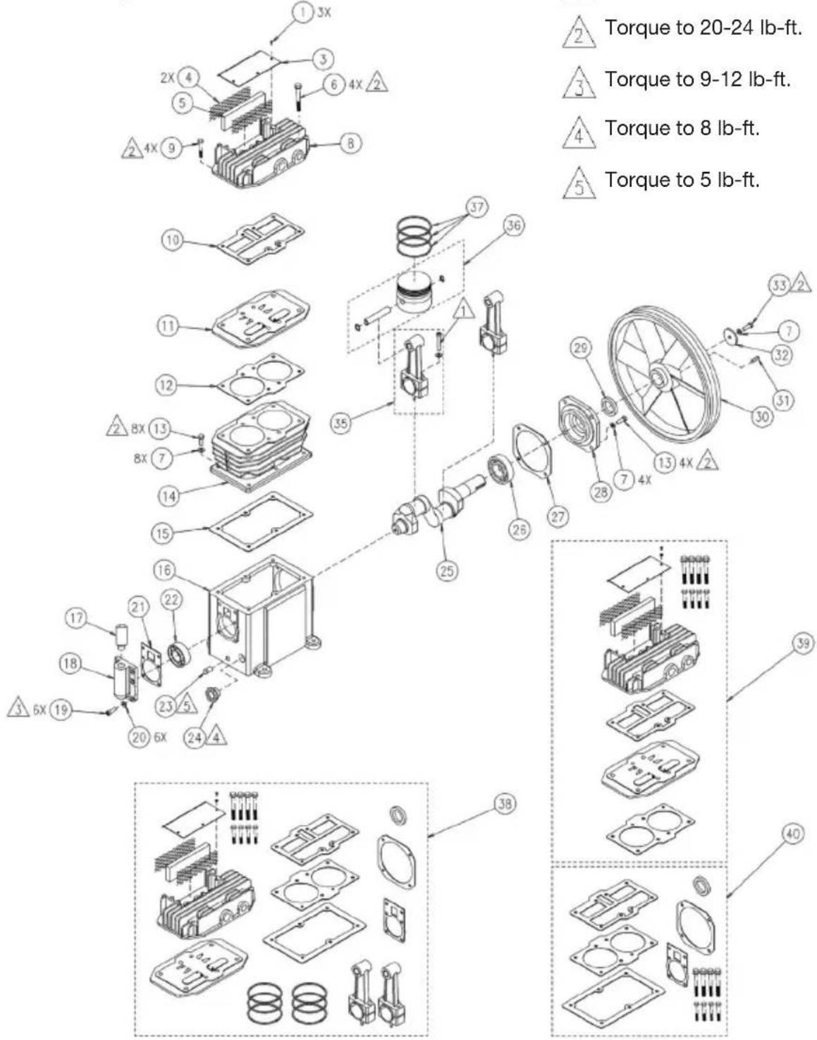
755H Pump Assembly
text_image
Torque to 20-24 lb-ft. Torque to 9-12 lb-ft. Torque to 8 lb-ft. Torque to 5 lb-ft.Notes:
Torque to 25-27 lb-ft.
Torque to 20-24 lb-ft.
3 Torque to 9-12 lb-ft.
4 Torque to 8 lb-ft.
5 Torque to 5 lb-ft.
text_image
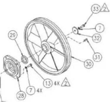
Technical diagram of a wheel assembly with numbered components and cross-sectional views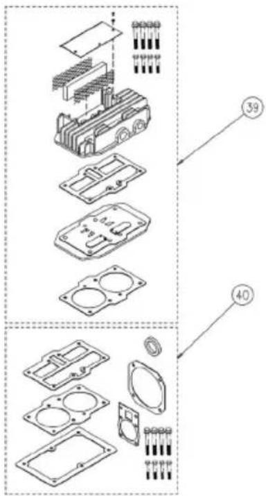
text_image
Exploded view diagram of an electronic component with numbered parts and exploded viewsPARTS LIST
Item Part No Qty Description
| 1 | 059-0424 3 Screw, M4x12 |
| 3 | 042-0112 1 Inlet cover |
| 4 | 118-0032 2 Screen |
| 5 | 019-0220 1 Filter, felt |
| 6 | 059-0412 4 Screw, M8x65 |
| 7 | 060-0222 9 Lock washer, M8 |
| 8 | 042-0108 1 Head assembly |
| 9 | 059-0465 4 Screw, M8x40 |
| 10 | 046-0283 1 Gasket, head |
| 11 | 043-0180 1 Valve plate assy (includes items 10 & 12) |
| 12 | 046-0282 1 Gasket, cylinder |
| 13 | 059-0415 12 Screw, M8x20 |
| 14 | 050-0061 1 Cylinder |
| 15 | 046-0281 1 Gasket, crankcase |
| 16 | 049-0048 1 Crankcase (includes item 22) |
| 17 | 056-0096 1 Breather |
| 18 | 077-0185 1 Cap (includes items 17 & 21) |
| 19 | 059-0418 6 Screw, M6 x 20 |
| 20 | 060-0220 6 Lock washer, M6 |
| 21 | 046-0280 1 Gasket |
| 22 | 051-0099 1 Bearing 205 |
| 23 | 062-0075 1 Oil drain plug, 3/8” NPT |
| 24 | 032-0126 1 Oil sight glass w/o-ring |
| 25 | 053-0100 1 Crankshaft |
| 26 | 051-0100 1 Bearing 206 |
| 27 | 046-0284 1 Gasket |
| 28 | 077-0172 1 Carrier |
| 29 | 046-0285 1 Oil seal |
| 30 | 044-0064 1 Flywheel, 12” A groove |
| 31 | 146-0026 1 Key, 5MM x 5 MM |
| 32 | 060-0228 1 Flywheel washer |
| 33 | 059-0419 1 Screw, M8 x 25 |
| 35 | 047-0086 2 Rod |
| 36 | 048-0116 2 Piston assembly |
| 37 | 054-0235 2 Ring Set |
Available Service Kits
| Part No | Description | |
| 38 | 165-0264 | Overhaul kitincludes items 1-6, 8-9, 11, 35, 37 and 40 |
| 39 | 042-0116 | Head and valve plate assyincludes items 1-6, 8-9, 10, 11 and 12 |
| 40 | 046-0279 | Gaskets, complete setincludes items 6, 9-10, 12, 15, 21, 27 and 29 |
| S040-0354 | Pump assemblyincludes items 1-37 excluding 30-33 |
LIMITED WARRANTY
Porter-Cable Industrial Tools are warranted from date of purchase.
2 Year – Limited warranty on oil-lubricated air compressor pumps.
1 Year – Limited warranty on all other air compressor components.
This warranty is not transferable to subsequent owners.
Porter-Cable will repair or replace, without charge, at Porter-Cable's option, any defects due to faulty materials or workmanship. For further detail of warranty coverage and warranty repair information, call 1-(888)-895-4549 or visit portercable.com. This warranty does not apply to accessories or damage caused where repairs have been made or attempted by others. This warranty also does not apply to merchandise sold by PORTER-CABLE which has been manufactured by and identified as the product of another company, such as gasoline engines. Such manufacturer's warranty, if any, will apply. ANY INCIDENTAL, INDIRECT OR CONSEQUENTIAL LOSS, DAMAGE OR EXPENSE THAT MAY RESULT FROM ANY DEFECT, FAILURE OR MALFUNCTION OF THE PRODUCT IS NOT COVERED BY THIS WARRANTY. Some states do not allow the exclusion of limitation of incidental or consequential damages, so the above limitation or exclusion may not apply to you. IMPLIED WARRANTIES, INCLUDING THOSE OF MERCHANTABILITY OR FITNESS FOR A PARTICULAR PURPOSE, ARE LIMITED TO ONE YEAR FROM THE DATE OF ORIGINAL PURCHASE. Some states do not allow limitations on how long an implied warranty lasts, so the above limitations may not apply to you.
What the Company Will Do: (the company) will cover parts and labor to remedy substantial defects due to materials and workmanship during the first year of ownership, with the exceptions noted below. Parts used in repair of whole goods or accessories are warranted for the balance of the original warranty period.
What is not covered Under This Warranty? Failures by the original retail purchaser to install, maintain, and operate said equipment in accordance with standard industry practices. Modifications to the product, or tampering with components, or failure to comply with the specific recommendations of the Company set forth in the owner's manual, will render this warranty null and void. The Company shall not be liable for any repairs, replacements, or adjustments to the equipment, or any costs for labor performed by the purchaser without the Company's prior written approval. The effects of corrosion, erosion, surrounding environmental conditions, cosmetic defects, and routine maintenance items, are specifically excluded from this warranty. Routine maintenance items such as: oil, lubricants, and air filters, as well as changing oil, air filters, belt tensioning, etc... fall under the owner's responsibility. Additional exclusions include: freight damage, failures resulting from neglect, accident, or abuse, induction motors when operated from a generator, oil leaks, air leaks, oil consumption, leaky fittings, hoses, petcocks, bleeder tubes, and transfer tubes.
- The following components are considered normal wear items and are not covered after the first year of ownership: Belts, sheaves, flywheels,
check valves, pressure switches, air unloaders, throttle controls, electric motors, brushes, regulators, o-rings, pressure gauges, tubing, piping, fittings, fasteners, wheels, quick couplers, gaskets, seals, air filter housings, piston rings, connecting rods, and piston seals.
- Labor, service calls, and travel charges, are not covered after the first year of ownership on stationary compressors (compressors without handles, or wheels). Repairs requiring overtime, weekend rates, or any other charges beyond the standard shop labor rate are not covered.
- Time required for orientation training for the service center to gain access to the product, or additional time due to inadequate egress.
- Damage caused by incorrect voltage, improperly wired, or failure to have a certified licensed electrician install the compressor, will render this warranty null and void.
- Damage caused from inadequate filter maintenance.
- Pump wear or valve damage caused by using oil not specified.
- Pump wear or damage caused by any oil contamination.
- Pump wear or valve damage caused by failure to follow proper maintenance guidelines.
• Operation below proper oil level or operation without oil. - Gas Engines, if product is equipped with a gas engine, see engine manual for specific engine manufacturer's warranty coverage.
Parts purchased separately: The warranty for parts purchased separately such as: pumps, motors, etc., are as follows:
From Date of Purchase
- All single & two stage pumps 1 year
• Electric motors
90
• Universal motor/pump 30 days
• All other parts 30 days
- No return authorization will be issued for electrical components once items are installed.
How do You Get Service? In order to be eligible for service under this warranty you must be the original retail purchaser, and provide proof of purchase from one of the Company's dealers, distributors, or retail outlet stores. Portable compressors or components must be delivered, or shipped, to the nearest Authorized Service Center. All associated freight costs and travel charges must be borne by the consumer. Please call our toll free number 1-888-895-4549 for assistance.
THIS WARRANTY GIVES YOU SPECIFIC LEGAL RIGHTS, AND YOU MAY ALSO HAVE OTHER RIGHTS WHICH VARY FROM STATE TO STATE. THE COMPANY MAKES NO OTHER WARRANTY OR REPRESENTATION OF ANY KIND WHATSOEVER, EXPRESSED OR IMPLIED, EXCEPT THAT OF TITLE. ALL IMPLIED WARRANTIES, INCLUDING ANY WARRANTY OF
MERCHANTABILITY AND FITNESS FOR PARTICULAR PURPOSE ARE HEREBY DISCLAIMED. LIABILITY FOR CONSEQUENTIAL AND INCIDENTAL DAMAGES UNDER ANY AND ALL WARRANTIES, OTHER CONTRACTS, NEGLEGENCE, OR OTHER TORTS IS EXCLUDED TO THE EXTENT EXCLUSION IS PERMITTED BY LAW.
FREE WARNING LABEL REPLACEMENT: If your warning labels become illegible or are missing, call 1-(888)-895-4549 for a free replacement.
text_image
WARNING AVERTISSEMENT ADVERTENCIA HOT SURFACES: To reduce the risk of rums - Do not touch exposed metal surfaces. SURFACES CHAUDES: Pour reducir le risque de brûlures - Ne pas touch aux surfaces métaliques exposées. SUPERFICIES CALIENTES: Para reducir el riesgo de sufrir quemaduras - No tocar las superficies metálicas expuestas.
text_image
WARNING: CONTAINS LEAD. May be harmful to order or chewed. May generate cold con learning lead. Wash hands after use. Keep out of reach of children. WARNING: This product can expose you to chemicals including Lead, which is known to the Store of California to cause cancer and birth defects or other reproductive harm. For more information go to www.PSSWarnings.ca.gov. ADVERTISSEMENT : CONTENT DU PLOME. Pour time model of astrogues de micrhe. Pour generator on la passable container du clone. Se lavantes maras, après usage. Garden hors de la portanto des enfants. ADVERTISSEMENT : Ce product journal vous expector à des produits chimiques, y compris Panib, recompi, par l'Etat de Californie comme cause de cancer, informations congénitales au autres prénomies ou système de reproduction. Pour obtenir plus d'information, visée www.PSSWarnings.ca.gov. ADVERTENCIA: CONTINE PLOME. Fauche sur caline si su ingente se maîche. Piedre generator plave que contarge pome. Àlvesse les manes descubés de uso. Manigelo fuore de alcance de les niños. ADVERTENCIA: Este coudere se cord la exponer à producteur culture suivierung Plame, reconduire por el Estado de California como causante de cancer, defectes de incendro etros carlos del sistema reproductive. Para obtenir más informació, visée www.PSSWarnings.ca.gov. 069-0173_A-218
text_image
WARNING For supply connection, use wires acceptable for at least 90°C. AVERTISSEMENT Pour la connexion d'alimentation, utilissez des fils pouvant supporter ou moins 90°C. ADVERTENCIA La connexion del suministro debe elec- urse con cables homologados para una temperatura de 90°C o mayor.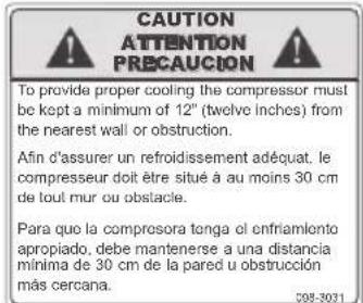
text_image
CAUTION ATTENTION PRECAUCTION To provide proper cooling the compressor must be kept a minimum of 12" (twelve inches) from the nearest wall or obstruction. Afin d'assurer un refroidissement adéquat. le compresseur doit être situé à au moins 30 cm de tout mur ou obstacle. Para que la compresora tenga el enfriamiento apropiado, debe mantenerse a una distancia minima de 30 cm de la pared u obstrucción más cercana.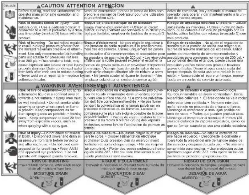
Cubic feet per minute; a unit of measure of air flow.
PSI
Pounds per square inch; a unit of measure of air pressure.
Kick-in pressure
Factory set low pressure point that starts the compressor to repressurize the tank to a higher pressure.
Kick-out pressure
Factory set high pressure point that stops the compressor from increasing the pressure in the tank above a certain level.
Well-ventilated
A means of providing fresh air in exchange for dangerous exhaust or vapors.
Dedicated circuit
An electrical circuit reserved for the exclusive use of the air compressor.
ASME
American Society of Mechanical Engineers.
Indicates that the components are manufactured, tested and inspected to the specifications set by ASME.
CSA

Canadian Standards Association
Indicates that the products that have this marking have been manufactured, tested and inspected to standards that are set by CSA.

Canadian Standards Association (USA)
Indicates that the products that have this marking have been
c US manufactured, tested and inspected to standards that are set by CSA. These products also conform to U.L. standard 1450.
PARTS AND SERVICE
Replacement parts and service are available from your nearest authorized Service Center. If the need arises, contact Product Service as listed at right.
When consulting with a Service Center or Product Service, refer to the model number and serial number located on the serial label of the compressor. Proof of purchase is required for all transactions and a copy of your sales receipt may be requested.
Record the model number, serial number, and date purchased in the spaces provided below. Retain your sales receipt and this manual for future reference.
When needing service, please contact the nearest authorized Service Center or call:
PRODUCT SERVICE
In U.S.A. or Canada
Toll-Free 1-888-895-4549
Fax 1-507-723-5013
Model No. Serial No. Date Purchased
Made in USA with domestic and foreign components
© 2020-2021 Sanborn Mfg.
Division of MAT Industries, LLC.
Springfield, MN 56087
1-888-895-4549
All Rights Reserved.
⚠️ AVERTISSEMENT
text_image
G OFF (C) AUTO (ON) (D)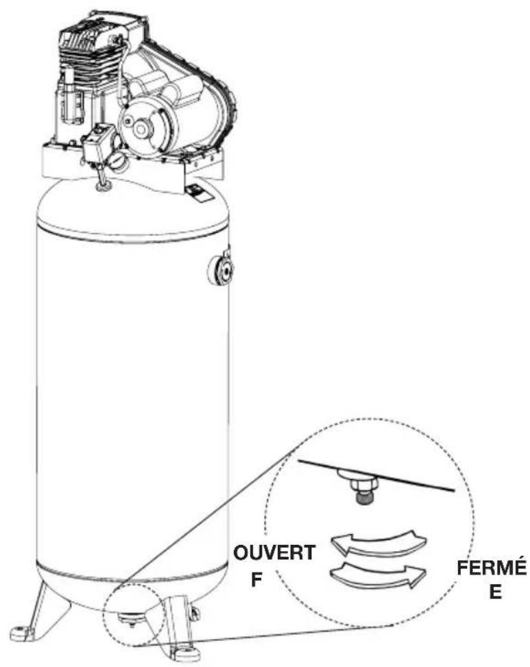
text_image
OUVERT F FERMÉ EMODE D'EMPLOI
MISE EN MARCHE QUOTIDIENNE (Fig. 6)
text_image
Exploded view diagram of a mechanical assembly with numbered parts and component labelsLISTE DE PIÈCES
Art N 0 / P Qté Description
| 1 | 059-0424 | 3 | Vis |
| 3 | 042-0112 | 1 | Couvercle |
| 4 | 118-0032 | 2 | Crépine |
| 5 | 019-0220 | 1 | Filtre |
| 6 | 059-0412 | 4 | Vis |
| 7 | 060-0222 | 9 | Rondelle |
| 8 | 042-0108 | 1 | Tête |
| 9 | 059-0465 | 4 | Vis |
| 10 | 046-0283 1 Joint, tête | ||
| 11 | 043-0180 1 Ensemble du plaque(inclut les éléments 10 et 12) | ||
| 12 | 046-0282 1 Joint, cylindre | ||
| 13 | 059-0415 | 12 | Vis |
| 14 | 050-0061 | 1 | Cylindre |
| 15 | 046-0281 | 1 | Joint, carter |
| 16 | 049-0048 | 1 | Carter (inclut les élément 22) |
| 17 | 056-0096 | 1 | Reniflard |
| 18 | 077-0185 | 1 | Chapeau (inclut les éléments 17 et 21) |
| 19 | 059-0418 | 6 | Vis |
| 20 | 060-0220 | 6 | Rondelle |
| 21 | 046-0280 | 1 | Joint |
| 22 | 051-0099 | 1 | Roulement |
| 23 | 062-0075 | 1 | Bouchon |
| 24 | 032-0126 1 Verre de vue de niveau d’huile | ||
| 25 | 053-0100 | 1 | Vilebrequin |
| 26 | 051-0100 | 1 | Roulement |
| 27 | 046-0284 | 1 | Joint |
| 28 | 077-0172 | 1 | Support |
| 29 | 046-0285 | 1 | Joint |
| 30 | 044-0064 1 Volant-moteur, A | ||
| 31 | 146-0026 | 1 | Clé |
| 32 | 060-0228 | 1 | Rondelle |
| 33 | 059-0419 | 1 | Vis |
| 35 | 047-0086 | 2 | Tige |
| 36 | 048-0116 2 Ensemble du piston | ||
| 37 | 054-0235 2 Jeu d’anneaux | ||
Available Service Kits
Model No. Serial No. Date Purchased
© 2020-2021 Sanborn Mfg.
Division of MAT Industries, LLC.
Springfield, MN 56087
1-888-895-4549
natural_image
Technical diagram of a mechanical assembly with three base platforms and a central component labeled 'C' (no text or symbols beyond label)Fig. 2
INSTALACION TIPICA
natural_image
Technical line drawing of a mechanical assembly with labeled component A, no readable text or symbols beyond labeltext_image
Exploded view diagram of a mechanical assembly with numbered parts and component labelsLISTE DE PIÈCES
Item Part No Qty Description
| 1 | 059-0424 | 3 | Tornillo |
| 3 | 042-0112 | 1 | Tapa |
| 4 | 118-0032 | 2 | Malla |
| 5 | 019-0220 | 1 | Filtro |
| 6 | 059-0412 | 4 | Tornillo |
| 7 | 060-0222 | 9 | Arandela |
| 8 | 042-0108 | 1 | Cabezal |
| 9 | 059-0465 | 4 | Tornillo |
Available Service Kits
American Society of Industrial Engineers.
Sanborn Mfg., Division of MAT Industries, LLC.
118 West Rock Street
Springfield, MN 56087
Model No. Serial No. Date Purchased
© 2020-2021 Sanborn Mfg.
Division of MAT Industries, LLC.
Springfield, MN 56087
1-888-895-4549