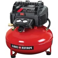
PXCM301 - Compressor Porter-Cable - Free user manual and instructions
Find the device manual for free PXCM301 Porter-Cable in PDF.


User questions about PXCM301 Porter-Cable
0 question about this device. Answer the ones you know or ask your own.
Ask a new question about this device
Download the instructions for your Compressor in PDF format for free! Find your manual PXCM301 - Porter-Cable and take your electronic device back in hand. On this page are published all the documents necessary for the use of your device. PXCM301 by Porter-Cable.
USER MANUAL PXCM301 Porter-Cable
Single Stage, Belt Drive, Electric Air Compressors
natural_image
Line drawing of a portable air compressor with visible wheels and control panel (no text or symbols)PXCM301
E107925 Rev. A 5-1-14
table of contents
SAFETY GUIDELINES 3-6
SPECIFICATION CHART 6
OVERVIEW 6
Basic Air Compressor Components....6
ASSEMBLY....7
Assembling the Compressor ....7
COMPRESSOR CONTROLS......8
ELECTRICAL POWER REQUIREMENTS ......9
Electrical Wiring 9
Extension Cords 9
Grounding Instructions 9-10
MOTOR 10-11
Motor Reset Switch 10-11
BREAK-IN OF THE PUMP....11
OPERATING INSTRUCTIONS 13
Daily Startup 13
Shutdown....13
MAINTENANCE....14-17
Draining the Tank....14
Checking the Oil 14
Changing the Oil....14
Belt Tension 15
Pulley Alignment....16
Cleaning the Air Filter 17
Checking the Relief Valve ....17
Testing for Leaks....17 Storage....17
SERVICE INTERVAL....17
TROUBLESHOOTING CHART 18-19
PARTS DRAWINGS AND PARTS LISTS.....20-21
WARRANTY....22-24
GLOSSARY OF TERMS 25
PARTS AND SERVICE 26
table Des MatlÈRes
CONSIGNES DE SÉCURITÉ ...... 3, 27-29
TABLEAU DES SPÉCIFICATIONS ......29
VUE D'ENSEMBLE....29
The following information relates to protecting YOUR SAFETY and PREVENTING EQUIPMENT PROBLEMS. To help you recognize this information, we use the following symbols. Please read the manual and pay attention to these sections.
DANGER
Indicates an imminently hazardous situation which, if not avoided, will result in death or serious injury.
WARNING
Indicates a potentially hazardous situation which, if not avoided, could result in death or serious injury.
CAUTION
Indicates a potentially hazardous situation which, if not avoided, may result in minor or moderate injury.
CONSIGNES DE SÉCURITÉ
Read and understand all safety precautions in this manual before operating. Failure to comply with instructions in this manual could result in personal injury, property damage, and/or voiding of your warranty. The manufacturer WILL NOT be liable for any damage because of failure to follow these instructions.

1. RIsK of fIRe oR
eXPloslon. Never spray flammable liquids in a confined area. It is normal for the motor and pressure switch to produce sparks while operating. If sparks come into contact with vapors from gasoline or other solvents, they may ignite, causing fire or explosion. Always operate the compressor in a well-ventilated area. Do not smoke while spraying. Do not spray where sparks or flame are present. Keep compressor as far from spray area as possible.

2. RIsK of electRlcal
sHocK. Never use an electric air compressor outdoors when it is raining or on a wet surface, as it may cause an electric shock.

- RIsK of InJuRy. This unit starts automatically. ALWAYS shut off the compressor, remove the plug from the outlet, and bleed all pressure from the system before servicing the compressor, and when the compressor is not in use. Do not use the unit with the shrouds or beltguard removed. Serious injury could occur from contact with moving parts.

- RIsK of buRstIng. Check the manufacturer's maximum pressure rating for air tools and accessories. Compressor outlet pressure must be regulated so as to never exceed the maximum pressure rating of the tool. Relieve all pressure through the hose before attaching or removing accessories.

- RIsK of buRns. High temperatures are generated by the pump and manifold. To prevent burns or other injuries, DO NOT touch the pump, manifold or transfer tube while the pump is running. Allow them to cool before handling or servicing. Keep children away from the compressor at all times.

- RIsK to bReatHIng. Be certain to read all labels when you are spraying paints or toxic materials, and follow the safety instructions. Use a respirator mask if there is a chance of inhaling anything you are spraying. Read all instructions and be sure that your respirator mask will protect you. Never directly inhale the compressed air produced by a compressor. It is not suitable for breathing purposes.

7. RIsK of eye InJuRy.
Always wear ANSI Z87.1 approved safety goggles when using an air compressor. Never point any nozzle or sprayer toward a person or any part of the body. Equipment can cause serious injury if the spray penetrates the skin.

- RIsK of buRstIng. Do not adjust the relief valve for any reason. Doing so voids all warranties. The relief valve has been pre-set at the factory for the maximum pressure of this unit. Personal injury and /or property damage may result if the relief valve is tampered with.

- RIsK of buRstIng.Do not use plastic or pvc pipe for compressed air. Use only gavanized steel pipe and fittings for compressed air distribution lines.
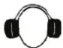
- RIsK to HeaRIng. Always wear hearing protection when using an air compressor. Failure to do so may result in hearing loss.

- The power cord on this product contains lead, a chemical known to the State of California to cause cancer, and birth defects or other reproductive harm. Wash hands after handling.
note: electRlcal wIRIng. Refer to the air compressor's serial label for the unit's voltage and amperage requirements.
Ensure that all wiring is done by a licensed electrician, in accordance with the National Electrical code.
DangeR

RIsK of buRstIng.
Air Tank: On February 26, 2002, the U.S. Consumer Product Safety Commission published Release # 02-108 concerning air compressor tank safety:
Air compressor receiver tanks do not have an infinite life. Tank life is dependent upon several factors, some of which include operating conditions, ambient conditions, proper installations, field modifications, and the level of maintenance. The exact effect of these factors on air receiver life is difficult to predict.
If proper maintenance procedures are not followed, internal corrosion to the inner wall of the air receiver tank can cause the air tank to unexpectedly rupture allowing pressurized air to suddenly and forcefully escape, posing risk of injury to consumers.
Your compressor air tank must be removed from service by the end of the year shown on your tank warning label.
The following conditions could lead to a weakening of the air tank, and result in a violent air tank explosion:
wHat can HaPPen How to PReVent It
- Failure to properly drain condensed water from air tank, causing rust and thinning of the steel air tank.
- Modifications or attempted repairs to the air tank.
- Unauthorized modifications to the safety valve, or any other components which control air tank pressure.
- Drain air tank daily or after each use. If air tank develops a leak, replace it immediately with a new air tank or replace the entire compressor.
- Never drill into, weld or make any modifications to the air tank or its attachments. Never attempt to repair a damaged or leaking air tank. Replace with a new air tank.
- The air tank is designed to withstand specific operating pressures. Never make adjustments or parts substitutions to alter the factory set operating pressures.
⚠waRnIng
- Drain the moisture from the tank on a daily basis. A clean, dry tank will help prevent corrosion.
- Pull the pressure relief valve ring daily to ensure that the valve is functioning properly, and to clear the valve of any possible obstructions.
- To provide proper ventilation for cooling, the compressor must be kept a minimum of 12 inches (31 cm) from the nearest wall, in a well-ventilated area.
- To prevent damage to tank and compressor on stationary models, the tank must be shimmed so the pump base is level within 1/8" to distribute oil properly. All feet must be supported, shimming where necessary, prior to attaching to the floor. Fasten all feet to floor. We also recommend the use of vibration pads (094-0137) under tank feet.
-
Fasten the compressor down securely if transporting is necessary. Pressure must be released from the tank before transporting.
-
Protect the air hose from damage and puncture. Inspect them weekly for weak or worn spots, and replace if necessary.
-
To reduce the risk of electric shock, do not expose to rain. Store indoors.
WARNING
CALIFORNIA PROPOSITION 65 WARNING: This product contains chemicals known to the State of California to cause cancer, birth defects and/or reproductive harm.
SPECIFICATION CHART
| MODEL NO. | RUNNING H.P. | TANK CAPACITY GALLONS | VOLTAGE/AMPS/PHASE | KICK-IN PRESSURE | KICK-OUT PRESSURE |
| PXCM301 | 1.6 30 (113,6) | 120151 | 125(8,6 bar) | 155(10,7 bar) |
BASIC AIR COMPRESSOR COMPONENTS
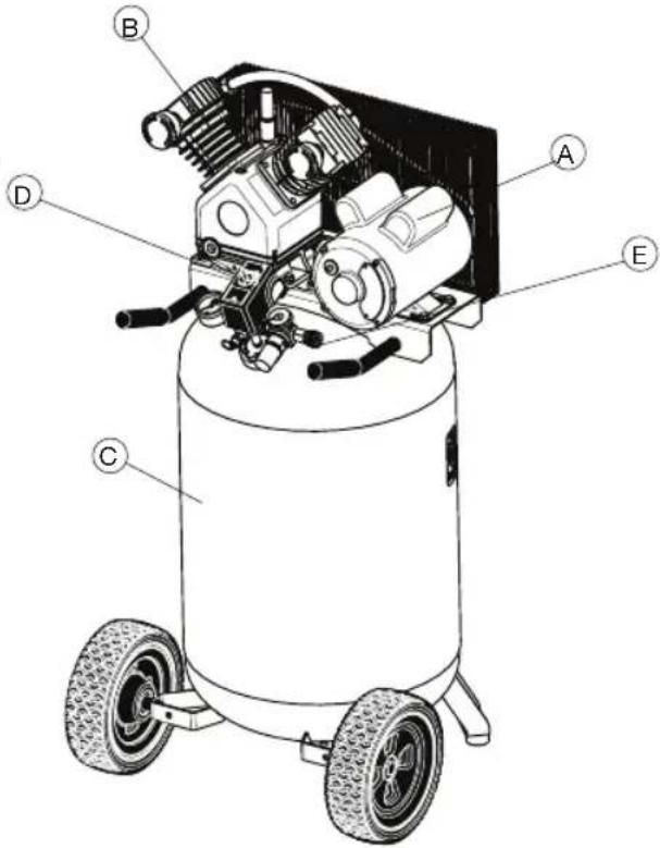
The basic components of the air compressor are the electric motor, pump, pressure switch and tank (see Fig. 1).
The electric motor (see A) powers the pump. The electric motor is equipped with an overload protector to help prevent possible motor burnout. If the motor becomes overheated, the overload protector will shut it down. Should this occur, allow the motor to cool for 10-15 minutes, then press (never force) the motor reset switch to restart the motor.
The pump (see B) compresses the air and discharges it into the tank.
The tank (see C) stores the compressed air.
The pressure switch (see D) shuts down the motor and relieves air pressure in the pump and transfer tube when the air pressure in the tank reaches the kick-out pressure. As compressed air is used and the pressure level in the tank drops to the kick-in pressure, the pressure switch restarts the motor automatically, without warning and the pump resumes compressing air.
The air line outlet (see E). Connect 1/4" NPT air hose to this outlet.
text_image
Technical diagram of an air compressor with labeled parts A through EFig. 1
ASSEMBLY
- Unpack the air compressor. Inspect the unit for damage. If the unit has been damaged in transit, contact the carrier and complete a damage claim. Do this immediately because there are time limitations to damage claims.
The carton should contain:
-
air compressor
• operator/parts manual -
Check the compressor's serial label to ensure that you have received the model ordered, and that it has the required pressure rating for its intended use.
-
Locate the compressor according to the following guidelines:
a. Position the compressor near a grounded electrical outlet (see GROUNDING INSTRUCTIONS). Avoid using an extension cord; use a longer hose instead.
b. The flywheel side of the compressor must be at least 12 inches (31 cm) from any wall or obstruction, in a clean, well-ventilated area, to ensure sufficient air flow and cooling.
c. In cold climates, store portable compressors in a heated building when not in use. This will reduce problems with lubrication, motor starting and freezing of water condensation.
d. The compressor must be level to ensure proper lubrication of the pump and good drainage of the moisture in the tank.
- Connect an air hose (not included) to the manifold outlet.
COMPRESSOR CONTROLS
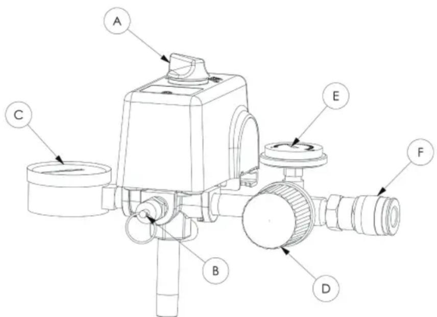
Refer to Fig. 3.
PRESSURE switch (see A)
This switch turns on the compressor. It is operated manually, but when in the ON position, it allows the compressor to start up or shut down automatically, without warning, upon air demand. ALWAYS set this switch to OFF when the compressor is not being used, and before unplugging the compressor.
Pressure Relief Valve (see B)
If the pressure switch does not shut down the motor when pressure reaches the preset level, this valve will pop open automatically to prevent over pressurization. To operate manually, pull the ring on the valve to relieve air pressure in the tank.
Tank Pressure Gauge (see C)
This gauge measures the pressure level of the air stored in the tank. It is not adjustable by the operator, and does not indicate line pressure.
Air Pressure Regulator (see D)
This air pressure regulator enables you to adjust line pressure to the tool you are using.
WARNING
Never exceed the maximum working pressure of the tool.
Turn the knob clockwise to increase pressure, and counterclockwise to decrease pressure.
Regulated pressure gauge (see E)
This gauge measures the regulated outlet pressure.
Air line outlet (see F)
Connect 1/4" NPT air hose to this outlet.
text_image
Technical diagram of a mechanical device with labeled parts A through FFig. 3
ELECTRICAL POWER REQUIREMENTS
ELECTRICAL WIRING
Refer to the air compressor's serial label for the unit's voltage and amperage requirements.
Use a dedicated circuit
For best performance and reliable starting, the air compressor must be plugged into a dedicated circuit, as close as possible to the fusebox or circuit breaker. The compressor will use the full capacity of a typical 15 amp household circuit. If any other electrical devices are drawing from the compressor's circuit, the compressor may fail to start. Low voltage or an overloaded circuit can result in sluggish starting that causes the motor overload protection system or circuit breaker to trip, especially in cold conditions.
NOTE: A circuit breaker is recommended. If the air compressor is connected to a circuit protected by a fuse, use dual element time delay fuses (Buss Fusetron type "T" only).
EXTENSION CORDS
NOTE: Avoid use of extension cords.
For optimum performance, plug the compressor power cord directly into a grounded wall socket. Do not use an extension cord unless absolutely necessary. Instead, use a longer air hose to reach the area where the air is needed.
If use of an extension cord cannot be avoided, the cord should be no longer than 50 feet and be a minimum wire size of 12 gauge (AWG). Do not use a 16 or 14 gauge extension cord.
Use only a 3-wire extension cord that has a 3-blade grounding plug, and a 3-slot receptacle that will accept the plug on the product. Make sure your extension cord is in good condition. An undersized cord will cause a drop in line voltage, resulting in loss of power and overheating. The smaller the gauge number, the heavier the cord.
GROUNDING INSTRUCTIONS
FOR CORD-CONNECTED MODELS:
This product should be grounded. In the event of an electrical short circuit, grounding reduces the risk of electric shock by providing an escape wire for the electric current.
This product is equipped with a cord having a grounding wire with an appropriate grounding plug. The plug must be plugged into an outlet that is properly installed and grounded in accordance with all local codes and ordinance.
Note: Not all units shipped with power cord.

⚠️ DANGER Improper installation of the grounding plug can result in a risk of electric shock. If repair or replacement of the cord or plug is necessary, do not connect the grounding wire to flat blade terminal. The wire insulation having an outer face that is green with or without yellow stripes is the winding wire.
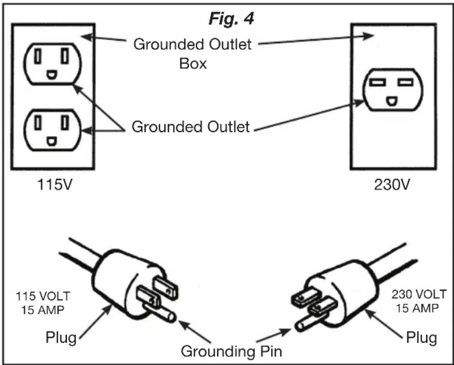
This product is for use on a nominal 115 volt circuit. A cord with a grounding plug, as shown here, shall be used.
Make sure that the product is connected to an outlet having the same configuration as the plug (see Fig. 4). No adapter should be used with this product.
Check with a licensed electrician if the grounding instructions are not completely understood, or if in doubt as to whether the product is properly grounded. Do not modify the plug provided; if it will not fit the outlet, have the proper outlet installed by a licensed electrician.
FOR PERMANENTLY CONNECTED MODELS OR MODELS SHIPPED
WITHOUT POWER CORD: This product must be connected to a grounded metallic, permanent wiring system, or an equipment grounding terminal or lead on the product.
text_image
Fig. 4 Grounded Outlet Box 115V Grounded Outlet 230V 115 VOLT 15 AMP Plug Grounding Pin 230 VOLT 15 AMP PlugMOTOR RESET SWITCH AND WIRING
⚠ WARNING Ensure that all guards and shrouds are in place before pressing the reset switch to restart the motor.
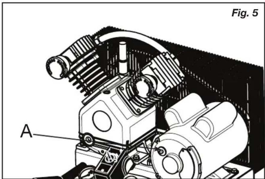
If the motor shuts down because of overload, wait 10–15 minutes so the motor can cool down, then press (NEVER force) the reset switch (see A) to restart the motor (see Fig. 5).
NOTE: Some models are equipped with a dual voltage motor 115/230 volt. Most models are factory wired for 115 volt operation. If conversion from 115 volt to 230 volt is required, refer to the motor nameplate and have the conversion completed by a Licensed Electrician.
Note: On stationary models not supplied with a power cord, the electrical power must be wired into the pressure switch by a Licensed Electrician.
natural_image
Technical illustration of a mechanical assembly with labeled component A, no readable text or symbols presentBREAK-IN OF THE PUMP
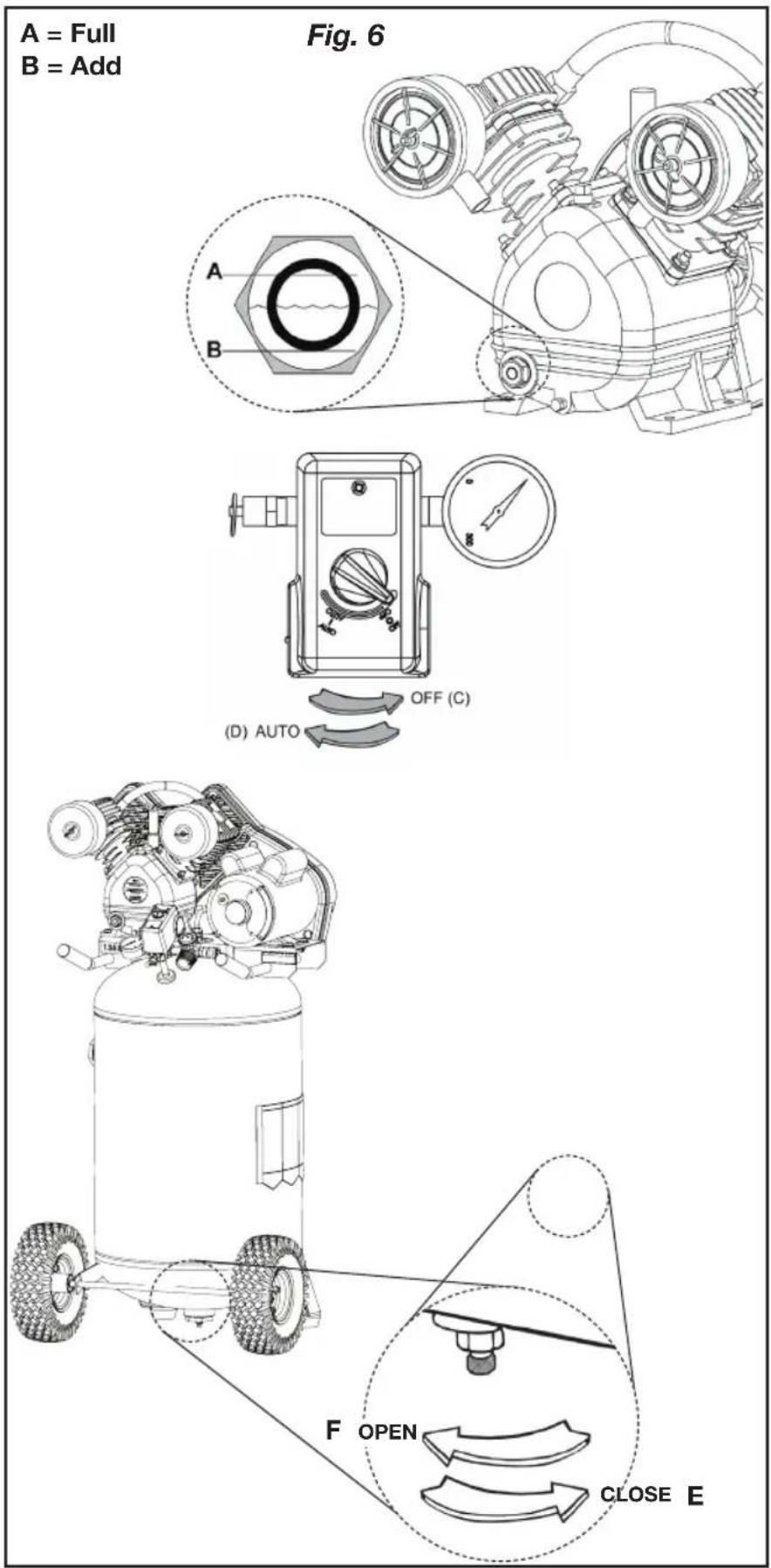
- Check the level of oil in the pump with the sight glass. The pump oil level must be between A and B (See Fig. 6). Do not overfill or underfill.
- Turn the pressure switch to the OFF position (see C).
- Open the petcock (see F).
- Plug in the power cord.
- Turn the pressure switch to the ON position (see D). The compressor will start. Allow the compressor to run for 30 minutes, to break in the internal parts.
NOTE: After about 30 minutes, If the unit does not operate properly, SHUT DOWN IMMEDIATELY, and contact Product Service.
-
After about 30 minutes, turn the pressure switch to the OFF position.
-
Close the petcock (see E).
-
Turn the pressure switch to the ON position. The compressor will start and fill the tank to the kick-out pressure and stop.
NOTE: As compressed air is used, the pressure switch will restart the motor automatically.
text_image
A = Full B = Add Fig. 6 A B (D) AUTO OFF (C) F OPEN CLOSE EOPERATING INSTRUCTIONS
DAILY STARTUP
- Every day check the sight glass to ensure that the level of oil in the pump is at the required level. The pump oil level must be between A and B (see Fig. 6). Do not overfill or underfill.
- Turn the pressure switch to the OFF position (see C).
- Close the tank petcock (see E).
- Plug in the power cord.

⚠ WARNING High temperatures are generated by the electric motor and the pump. To prevent burns or other injuries, DO NOT touch the compressor while it is running. Allow it to cool before handling or servicing. Keep children away from the compressor at times.
- Turn the pressure switch to the ON position (see D).

⚠ WARNING When adjusting from a higher to a lower pressure, turn the knob counterclockwise past the desired setting, then turn clockwise to reach the desired pressure. Do not exceed operating pressure of the tool or accessory being used.
- If a pressure regulator is present on your compressor, adjust it to the working pressure of the tool.
SHUTDOWN
- Turn the pressure switch to the OFF position (see C).
- Unplug the power cord.
- Reduce pressure in the tank through the outlet hose. You can also pull the relief valve ring (see G) and keep it open to relieve pressure in the tank.

⚠ WARNING Escaping air and moisture can propel debris that may cause eye injury. Wear safety goggles when opening petcock.
- Open the petcock (see F) to allow moisture to drain from the tank.
MAINTENANCE
MAINTENANCE
⚠ WARNING To avoid personal injury, always shut off and unplug the compressor and relieve all air pressure from the system before performing any service on the air compressor.
Regular maintenance will ensure trouble-free operation. Your electric powered air compressor represents high-quality engineering and construction; however, even high-quality machinery requires periodic maintenance. The items listed below should be inspected on a regular basis
DRAINING THE TANK

WARNING
moisture must be
Condensation will accumulate in the tank. To prevent corrosion of the tank from the inside, this is drained at the end of every workday.

WARNING
WARNING Be sure to wear protective eyewear. Relieve the air pressure in the system and open the petcock on the bottom of the tank to drain.
CHECKING THE OIL
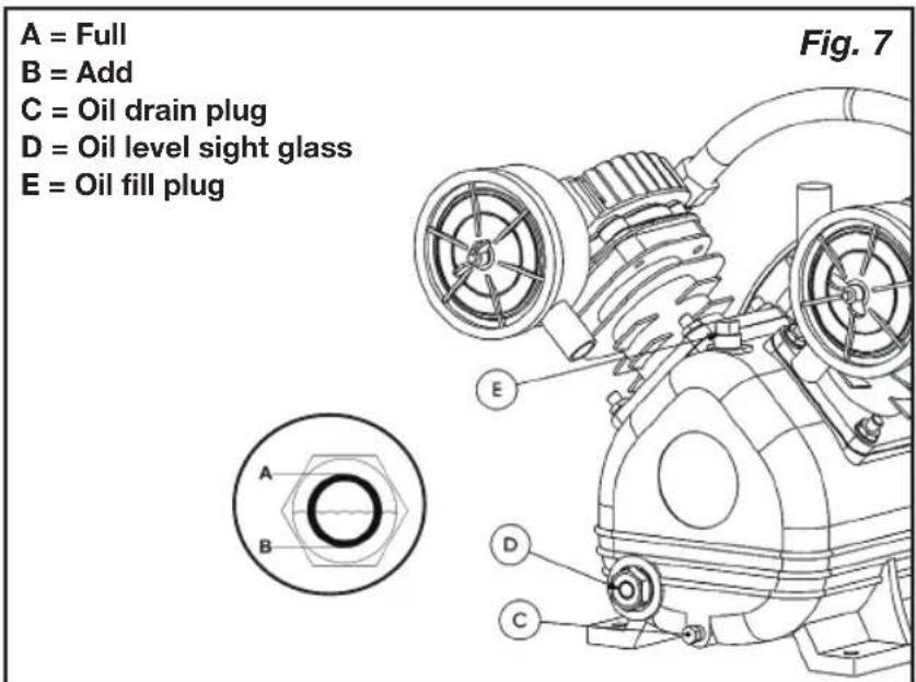
Check the level of oil in the pump with the sight glass. The pump oil level must be between A and B (See Fig. 7). Do not overfill or underfill.
CHANGING THE OIL
NOTE: Use synthetic blend, nondetergent air compressor oil.
Remove the oil plug (C) (Fig. 7) and drain the oil until it slows to a drip, then close. Add oil to the pump by first removing the breather plug (E). Add oil until the level viewed through the sight glass (D) is between FULL (A) and ADD (B) (approx. 11.35 oz). Never overfill or underfill the pump.
NOTE: The compressor is pre-filled with synthetic oil. Use synthetic blend, nondetergent air compressor oil.
text_image
A = Full B = Add C = Oil drain plug D = Oil level sight glass E = Oil fill plug Fig. 7BELT TENSION AND PULLEY ALIGNMENT
WARNING
To avoid personal injury, always shut off and unplug the compressor and relieve all air pressure from the system
before performing any service on the air compressor.
NOTE: Drive belt tensioning and pulley alignment are done at the same time.
They are discussed separately for clarity.
ADJUSTING DRIVE BELT TENSION
Proper belt tension and pulley alignment must be maintained for maximum drive efficiency and belt life. The correct tension exists if a deflection (see A) of 1/2" (13 mm) occurs by placing 5 lb (2.3 kg) of force (see B) midway between the motor pulley and the pump flywheel (See Fig. 8). This deflection can be adjusted by the following procedure. The pulley should be carefully aligned with the flywheel, and all setscrews should be kept tight.
- Remove the belt guard.
- Loosen the motor mounting bolts.
- Shift the motor to the point where the correct deflection exists.
- Retighten the motor mounting bolts.
- Check to ensure that the tension remained correct.
- Reinstall the belt guard. All moving parts must be guarded.
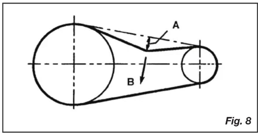
text_image
A B Fig. 8Pulley alignMent
To check pulley alignment, remove the belt guard and place a straightedge (see a) against the pump flywheel (see b) (See Fig. 9). Measure and record the distance from the straightedge to the edge of the drive belt at point C. Then measure the distance from the straightedge to the edge of the drive belt again at points D and E. Both distances should be the same as at point C. If D or E are different from C, there is a misalignment which must be corrected before the compressor is run. To correct a pulley misalignment, use the following procedure.
- Remove the belt guard.
- Loosen the motor mounting bolts.
- Loosen the setscrew on the motor pulley.
- Align the motor pulley with the pump flywheel (c = D = e).
- Retighten the motor pulley setscrew.
- Adjust the proper belt tension.
- Retighten the motor mounting bolts.
- Reinstall the belt guard. All moving parts must be guarded.
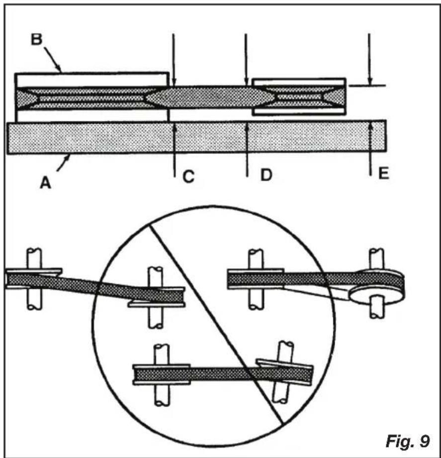
text_image
B A C D E Fig. 9MAINTENANCE
CLEANING THE AIR FILTER
A dirty air filter will reduce the compressor's performance and life. To avoid any internal contamination of the pump, the filter should be cleaned frequently, and replaced on a regular basis. Felt filters should be cleaned in warm, soapy water, rinsed, and allowed to air dry before reinstallation. Paper filters should be replaced when dirty. Do not allow the filter to become filled with dirt or paint. If the filter becomes filled with paint, it should be replaced. Direct exposure to dirty conditions or painting areas will void your warranty.
CHECKING THE RELIEF VALVE
Pull the relief valve daily to ensure that it is operating properly and to clear the valve of any possible obstructions.
TESTING FOR LEAKS
Check that all connections are tight. A small leak in any of the hoses, transfer tubes, or pipe connections will substantially reduce the performance of your air compressor. If you suspect a leak, spray a small amount of soapy water around the area of the suspected leak with a spray bottle. If bubbles appear, repair or replace the faulty component. Do not overtighten any connections.
STORAGE
Before storing the compressor for a prolonged period, use an air blow gun to clean all dust and debris from the compressor. Disconnect the power cord and coil it up. Pull the pressure relief valve to release all pressure from the tank. Drain all moisture from the tank. Clean the filter element and filter housing; replace the element if necessary. Drain the oil from the pump crankcase and replace it with new oil. Cover the entire unit to protect it from moisture and dust.
SERVICE INTERVAL
Perform the following maintenance at the intervals indicated below.
Inspect and clean air filter ....Daily
Check pump oil level....Daily
Change pump oil ...... Every 100 operating hours
Use synthetic blend, nondetergent air compressor oil.
Operate the pressure relief valves....Daily
Check belt tension ...... Every 50 operating hours
Drain tank....Daily
Check and tighten all bolts
(Do not overtighten) .... Every 100 operating hours
TROUBLESHOOTING
Note: Troubleshooting problems may have similar causes and solutions.
| PROBLEM POSSIBLE | CAUSE SOLUTION | |
| Excessive current draw trips circuit breaker of motor reset switch | Low voltage/motor overload | Check that power supply is adequate and that compressor is on a dedicated circuit. If using extension cord, try using without. If compressor is connected to a circuit protected by a fuse, use dual element time delay fuses (Buss Fusetron type “T” only). |
| Drive belt too tight Readjust belt tension | ||
| Restricted air passages Inspect and replace transfer tubes or check valve, as required. | ||
| Compressor stalls | Low voltage motor Furnish adequate power. | |
| Bad check valve Replace the check valve. | ||
| Seized pump Contact authorized service center. | ||
| Low discharge pressure | Air leaks Tighten or replace leaking fittings or connections. Do not overtighten. | |
| Leaking valves Contact authorized service center. | ||
| Restricted air intake Clean or replace air filter element(s). | ||
| Blown gaskets Contact authorized service center. | ||
| Worn piston rings or cylinder | Contact authorized service center. | |
| Compressor pump knocking | Loose engine pulley or compressor flywheel | Retighten pulley and flywheel. Check alignment. |
| Low oil level in pump crankcase | Keep oil at proper level at all times. | |
| Excess carbon on valves or top of piston | Contact authorized service center. | |
| Oil in discharge air | Worn piston rings or cylinder | Contact authorized service center. |
| Restricted air intake Clean | or replace the air filter element(s). | |
| Oil level too high Reduce to proper level. | ||
| Overheating | Poor ventilation Relocate | compressor to an area with cool, dry, well circulated air, at least 12 in. from nearest wall. |
| Dirty cooling surfaces Clean all cooling surfaces thoroughly. | ||
| Restricted air passages Replace transfer tubes and/or unloader. | ||
| Excessive belt wear | Pulley out of alignment Realign pulley with compressor flywheel. | |
| Improper belt tension Readjust. | ||
| Pulley wobbles Replace the pulley and check for a damaged crankshaft or flywheel. | ||
| Compressor won't start in cold temperatures | Too much back pressure in tank | Open petcock when starting motor. |
| 40W oil in crankcase Use synthetic blend, nondetergent air compressor oil. | ||
| Compressor too cold Move compressor to a warmer location. | ||
LIMITED WARRANTY
Porter-Cable Industrial Tools are warranted from date of purchase.
2 Year – Limited warranty on oil-lubricated air compressor pumps.
1 Year – Limited warranty on all other air compressor components.
This warranty is not transferable to subsequent owners.
Porter-Cable will repair or replace, without charge, at Porter-Cable's option, any defects due to faulty materials or workmanship. For further detail of warranty coverage and warranty repair information, call 1-(888)-895-4549 or visit portercable.com. This warranty does not apply to accessories or damage caused where repairs have been made or attempted by others. This warranty also does not apply to merchandise sold by PORTER-CABLE which has been manufactured by and identified as the product of another company, such as gasoline engines. Such manufacturer's warranty, if any, will apply. ANY INCIDENTAL, INDIRECT OR CONSEQUENTIAL LOSS, DAMAGE OR EXPENSE THAT MAY RESULT FROM ANY DEFECT, FAILURE OR MALFUNCTION OF THE PRODUCT IS NOT COVERED BY THIS WARRANTY. Some states do not allow the exclusion of limitation of incidental or consequential damages, so the above limitation or exclusion may not apply to you. IMPLIED WARRANTIES, INCLUDING THOSE OF MERCHANTABILITY OR FITNESS FOR A PARTICULAR PURPOSE, ARE LIMITED TO ONE YEAR FROM THE DATE OF ORIGINAL PURCHASE. Some states do not allow limitations on how long an implied warranty lasts, so the above limitations may not apply to you.
What the Company Will Do: (the company) will cover parts and labor to remedy substantial defects due to materials and workmanship during the first year of ownership, with the exceptions noted below. Parts used in repair of whole goods or accessories are warranted for the balance of the original warranty period.
What is not covered Under This Warranty? Failures by the original retail purchaser to install, maintain, and operate said equipment in accordance with standard industry practices. Modifications to the product, or tampering with components, or failure to comply with the specific recommendations of the Company set forth in the owner's manual, will render this warranty null and void. The Company shall not be liable for any repairs, replacements, or adjustments to the equipment, or any costs for labor performed by the purchaser without the Company's prior written approval. The effects of corrosion, erosion, surrounding environmental conditions, cosmetic defects, and routine maintenance items, are specifically excluded from this warranty. Routine maintenance items such as: oil, lubricants, and air filters, as well as changing oil, air filters, belt tensioning, etc... fall under the owner's responsibility. Additional exclusions include: freight damage, failures resulting from neglect, accident, or abuse, induction motors when operated from a generator, oil leaks, air leaks, oil consumption, leaky fittings, hoses, petcocks, bleeder tubes, and transfer tubes.
- The following components are considered normal wear items and are not covered after the first year of ownership: Belts, sheaves, flywheels,
check valves, pressure switches, air unloaders, throttle controls, electric motors, brushes, regulators, o-rings, pressure gauges, tubing, piping, fittings, fasteners, wheels, quick couplers, gaskets, seals, air filter housings, piston rings, connecting rods, and piston seals.
- Labor, service calls, and travel charges, are not covered after the first year of ownership on stationary compressors (compressors without handles, or wheels). Repairs requiring overtime, weekend rates, or any other charges beyond the standard shop labor rate are not covered.
- Time required for orientation training for the service center to gain access to the product, or additional time due to inadequate egress.
- Damage caused by incorrect voltage, improperly wired, or failure to have a certified licensed electrician install the compressor, will render this warranty null and void.
• Damage caused from inadequate filter maintenance. - Pump wear or valve damage caused by using oil not specified.
- Pump wear or damage caused by any oil contamination.
- Pump wear or valve damage caused by failure to follow proper maintenance guidelines.
• Operation below proper oil level or operation without oil.
Gas Engines, if product is equipped with a gas engine, see engine manual for specific engine manufacturer's warranty coverage.
Parts purchased separately: The warranty for parts purchased separately such as: pumps, motors, etc., are as follows:
From Date of Purchase
• All single & two stage pumps 1 year
• Electric motors 90 days
• Universal motor/pump 30 days
• All other parts 30 days
- No return authorization will be issued for electrical components once items are installed.
How do You Get Service? In order to be eligible for service under this warranty you must be the original retail purchaser, and provide proof of purchase from one of the Company's dealers, distributors, or retail outlet stores. Portable compressors or components must be delivered, or shipped, to the nearest Authorized Service Center. All associated freight costs and travel charges must be borne by the consumer. Please call our toll free number 1-888-895-4549 for assistance.
THIS WARRANTY GIVES YOU SPECIFIC LEGAL RIGHTS, AND YOU MAY ALSO HAVE OTHER RIGHTS WHICH VARY FROM STATE TO STATE.
THE COMPANY MAKES NO OTHER WARRANTY OR REPRESENTATION OF ANY KIND WHATSOEVER, EXPRESSED OR IMPLIED, EXCEPT THAT OF TITLE. ALL IMPLIED WARRANTIES, INCLUDING ANY WARRANTY OF
MERCHANTABILITY AND FITNESS FOR PARTICULAR PURPOSE ARE HEREBY DISCLAIMED. LIABILITY FOR CONSEQUENTIAL AND INCIDENTAL DAMAGES UNDER ANY AND ALL WARRANTIES, OTHER CONTRACTS, NEGLEGENCE, OR OTHER TORTS IS EXCLUDED TO THE EXTENT EXCLUSION IS PERMITTED BY LAW.
fRee waRnIng label RePlaceMent: If your warning labels become illegible or are missing, call 1-(888)-895-4549 for a free replacement.

text_image
WARNING HOTSURFACE. RISK OF BURNS. DO NOT TOUCH. ADVERTENCIA SUPERFICIECALIENTE. RIESGO DE QUEMADURAS. NO TOCAR. AVERTISSEMENT SURFACETRÈSCHAUDE. RISQUES DE BRÛLURES. NE PAS TOUCHER. N008806
text_image
CAUTION LEER EL MANUAL DEL OPERADOR. ANTES DE ARRANCAR EL COMPRESOR, LEER LAS INSTRUCCIONES DE SEGURIDAD, OPERACIÓN Y MANTENIMIENTO EN EL MANUAL DEL OPERADOR. RISK OF BURRITING, BEFORE STARTING COMPRESSOR, PULL SAFETY VALVE RING TO MAKE SURE THE VALVE MOVES FREELY, DO NOT EXCEED RATED PRESSURE OF ATTACHMENTS AIR TOOLS, ACCESSORIES, INFATABLES, ETCI, INSTALL REGULATOR BEFORE USING MOST ATTACHMENTS, AND ADJUST AIR PRESSURE BELOW MAXIMUM RATED PRESSURE OF ATTACHMENT. IF A REGULATOR IS NOT SUPPLIED. USE ONLY ATTACHMENTS RATED AT 200 PSI OR HIGHER, DRAIN TANK DAILY, CONDENSED WATER WILL. CAUSE RUSTING AND RISK OF TANK RUCTURE OR EXPLOSION, DO NOT REPAIR, MODIFY OR WELD TANK, RETURN TO AUTHORIZED SERVICE CENTER IF REPLACEMENT IS REQUIRED. DO NOT USE PLASTIC PIPE FOR AIR REGARDLESS OF ITS PRESSURE RATING. RISK OF ELECTRIC SHOCK, DISCONNECT AIR COMPRESSOR FROM ELECTRICAL SUPPLY CIRCUIT BEFORE SERVENCING, DO NOT EXPOSE COMPRESSOR TO RAW OR OPERATE IN A WET AREA, STORE INDOORS. RISIGO DE ESTALLIDO. ANTES DE ARRANCAR EL COMPRESOR, TRAR DEL ANLLO DE LA VALVULA PARA SEGUARÍNE QUE ESTA SE VUEVA LIBRIMENTO, NO EXEDER LA PRESEN ESPECIFICADA PARA LOS ACCESORIOS HERRAMENTAS NEUMATICAS ARTICULOS INFLABIES, ETCI., LA MAYNÍA DE ACCESORIOS REQUEREN QUE SE INSTALE UN REGULADOR Y QUE LA PRESNIÓN DE ARE SE GRADUE POR DEBALO DE LA PRESNIÓN MAXIMA ESPECIFICADA PARA EL ACCESORIO. SINO SE INSTALA UN REGULADOR, USO SOLÚ ESCECOSORIOS ESPECIFICADOS PARA 200 PSI O VÁS DRENAR EL TANQUE DANIAMIENTO. LA CONDENSACIÓN DE AGUA PUEDE OXIDAR EL TANQUE Y CREAR UN RIESGO DE RUPTURA O ESTALJADO. NO REPAIR, MODIFICAR NO SOLDER EL TANQUE, LLEVIVILDA A UN CENTRO DE SERVICIO AUTORIZADO PARA QUE LD CAMBIEN, NO USAU TUBENA PLASTICA PARA EL ARE AVANQUE ESTÉ CERTIFICADA PARA LA PRESIÓN DEL COMPRESOR. RISIGO DE CHOQUE ELECTRICO. DESCONECTE EL SUMINISTRO ELECTRICO DEL COMPRESOR DE ARE ANTES DE DARLE SERVICIO. NO EXPONGA EL COMPRESOR DE ARE A LA LLUVA NÓ OPERARLO EN AREAS MOJADAS, ALMAGENAR EN INTEDIORES. WARNING ADVERTENCIA RIESGO DE LESIONES PERSONALES, EL ARE COMPRIMIDO PUEDE SER PELLIGRIDO, EL CHORDO DE ARE Y LOS OBJETOS O PARTICULAS QUE PRODUZ SA PUEDEN CANAL LEONINES, USE ANTEUDOS DE SEGURIDAD ANIZ ZKT. NO DIRIGER EL CHORDO DE ARE AL CUERPO N A LA CASA, DRENAR LA PRESIÓN DEL TANQUE ANTES DE DARLE SERVICIO AL COMPRESOR, RIESGO DE PIEZAS MOVILES, DESCONECTE EL COMPRESOR DEL SUMINISTRO DE ARE ANTES DE DARLE SERVICIO, LA UNIDAD ARRANGA AUTOMÁTICAMENTE, NO OPERAR LN LAS CUVERTAS PROTECTORAS O SE ESTÁN ROTAS, EL MATERIAL ROCADO PUEDE SER TÓVICO. COMO PROTECCIÓN SEMPRE USE MÁSCARAS OR RESPRADORES APROBADOS POR NSHA/MOSH. NO USE EL ARE COMPRIMIDO PARA RESPRAR. RISIGO DE INCENDIO O EXPLOSHÓN LOS COMPRESORES ELECTRICOS PRODUCEN ARCOS ELECTRICOS, NO ROCAR, LIQUIDS INFLAMABLES NI COMBUSTIBLES CERCA DE CHISPAS, LLAMAS, PILLOT PILOT O EN AREAS CONFRANDAS, ROCAR EN AREAS BIENVITILADAS, MAINTENER EL COMPRESOR A POR LO MENOS 20 PES DEL AREA DE PULVERIZADO. NO FUMAR MENTRAS SE ESTÁ NUE PERVEZANDO, UVAR UNA MANGUERA DE MINIMO DE 15 PES DE LARGO PARA CONECTIVA LA PISTOLA VOPERIZADORA AL COMPRESOR. RISIGO D'ÉCLATEMENT PREVENIR LA CORROSION EN DRAINANT TOUTE HUMIDITÉ DU RÉSERVOIR APRÉS CHAQUE USAGE. DRENAR LA VALVULA UBICADA DEBAJO DEL TANQUE. RISIGO DE EXPLOSIÓN PREVENIR LA CORROSION DEL TANQUE. DESPUÉS DE CADA USO DRENAR TODA HUMEDAD DEL TANQUE. SOUPAPE DE VIDANGE SITUÉE SUR LE DESSOUS DU RÉSERVOI.glossaRy of teRMs
CFM
Cubic feet per minute; a unit of measure of air flow.
PSI
Pounds per square inch; a unit of measure of air pressure.
Kick-in pressure
Factory set low pressure point that starts the compressor to repressurize the tank to a higher pressure.
Kick-out pressure
Factory set high pressure point that stops the compressor from increasing the pressure in the tank above a certain level.
Well-ventilated
A means of providing fresh air in exchange for dangerous exhaust or vapors.
Dedicated circuit
An electrical circuit reserved for the exclusive use of the air compressor.
ASME
American Society of Mechanical Engineers.
Indicates that the components are manufactured, tested and inspected to the specifications set by ASME.

Canadian Standards Association
Indicates that the products that have this marking have been manufactured, tested and inspected to standards that are set by CSA.

c US Canadian Standards Association (USA)
Indicates that the products that have this marking have been manufactured, tested and inspected to standards that are set by CSA. These products also conform to U.L. standard 1450.
PARTS AND SERVICE
Replacement parts and service are available from your nearest authorized Service Center. If the need arises, contact Product Service as listed below.
When consulting with a Service Center or Product Service, refer to the model number and serial number located on the serial label of the compressor. Proof of purchase is required for all transactions and a copy of your sales receipt may be requested.
Record the model number, serial number, and date purchased in the spaces provided below. Retain your sales receipt and this manual for future reference.
When needing service, please contact the nearest authorized Service Center or call:
PRODUCT SERVICE
In U.S.A. or Canada
Toll-Free 1-888-895-4549
Fax
1-507-723-5013
Model No. Serial No. Date Purchased
Made in USA with domestic and foreign components
© 2014 MAT Industries, LLC
Jackson, TN 38301
1-888-895-4549
All Rights Reserved.
aVeRtIsseMent
natural_image
Technical illustration of an internal combustion engine assembly (no text or symbols visible)RoDage De la PoMPe
© 2014 MAT Industries, LLC
Jackson, TN 38301
1-888-895-4549
natural_image
Technical illustration of an internal combustion engine assembly (no text or symbols visible)RoDaJe De la boMba
American Society of Industrial Engineers.
© 2014 MAT Industries, LLC
Jackson, TN 38301
1-888-895-4549