60883 - Electronic module Märklin - Free user manual and instructions
Find the device manual for free 60883 Märklin in PDF.

| Product type | Electronic feedback module (S88 Link) |
| Brand | Märklin |
| Model | 60883 |
| Power supply | Märklin cutoff power supply 66361 or 66201 (5V or 12V depending on configuration) |
| Number of contacts | 16 signaling contacts (expandable to 64 in matrix mode) |
| Central Station compatibility | Central Station 60213/60214/60215 (software version 3.8.xx or later) and Terminal 60125 |
| Supported S88 buses | Up to 31 S88 modules and/or 62 S88AC/S88DC modules |
| Use | Track feedback (center conductor H0 or 2L), track contact, key matrix (switchboard) |
| Connection | Booster socket of the Central Station or terminal, RJ45 connection for S88 bus |
| Configuration | Via the Central Station: Setup/Info menu, then advanced configuration (tool icon) |
| Addressing | Automatic upon connection; default addresses: contacts 1-16, keys 101-164, bus 1-3 |
| Safety | Do not open the housing; use only in dry rooms; disconnect before any wiring |
| Maintenance and cleaning | No special maintenance; clean with a dry, lint-free cloth |
| Spare parts and repairability | Contact a specialized Märklin dealer for any repairs; legal and contractual warranty (see certificate) |
| General information | Operating instructions to be kept and passed on with the product; proper disposal (www.maerklin.com/imprint) |
Frequently Asked Questions - 60883 Märklin
User questions about 60883 Märklin
0 question about this device. Answer the ones you know or ask your own.
Ask a new question about this device
Download the instructions for your Electronic module in PDF format for free! Find your manual 60883 - Märklin and take your electronic device back in hand. On this page are published all the documents necessary for the use of your device. 60883 by Märklin.
USER MANUAL 60883 Märklin
Using the Product as Intended 14
Safety Notes 14
Important Notes 14
Inputs and Outputs for the Link 88 14
Connect 15
Overview of Connections 16
Configuration for the L88 18
Use as a Button Matrix 22
Inhoudsopgave :
Pagina
Beoogd gebruik 34
Using the Product as Intended
- The L88 feedback module is designed for connection to the L88 (60883) and the 60213/60214/60215 Central Stations (CS2) with Software Version 3.8.xx and higher.
- Connections from the 6088/60880/60881 and 60882 feedback modules to the Central Station units mentioned above.
- The L88 Link feedback module is a position indicator with 16 indicator contacts for Märklin H0 center conductor track or for 2-rail track (1 Gauge, Trix H0, Minitrix) with reed contacts.
- Or connections to 64 button controllers.
Safety Notes
- The voltage supply for the L88 Link is done only by means of the 66361/66365 or 66201 switched mode power pack.
- Connections to the L88 Link feedback module may only be done with no voltage present.
- WARNING! Sharp edges and points required for operation.
• The housing must not be opened. - The L88 Link feedback module is designed only for use in dry areas.
Important Notes
- The operating instructions are a component part of the product and must therefore be kept in a safe place as well as included with the product, if the latter is given to someone else.
- Please see your authorized Märklin dealer for repairs
- The warranty card included with this product specifies the warranty conditions.
- Disposing: www.maerklin.com/en/imprint.html
Inputs and Outputs for the Link 88
Current supply: 66361/66365 or 66201 switched mode power pack. Connections to the Central Station / Terminal
Ground return (when used as a position indicator)
1-16 Contact connections (Märklin H0 center conductor track or button controllers)
Bus 1 60881 or 60882
Bus 2 60881 or 60882
Bus 3 6088 and/or 60880
Switches for current supply to the S88 Module with 5 volts or 12 volts.

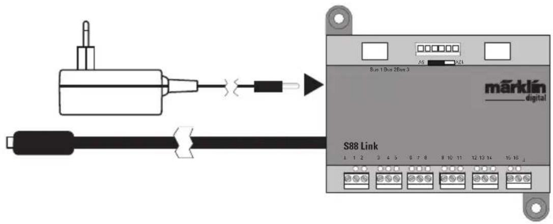
Connect
Connections to the Central Station
Connect the Link 88 directly to the Booster connection on the CS2 or to the 60125
Terminal. After that plug in the 66361/66365 or 66201 power supply.
Central Station / Terminal
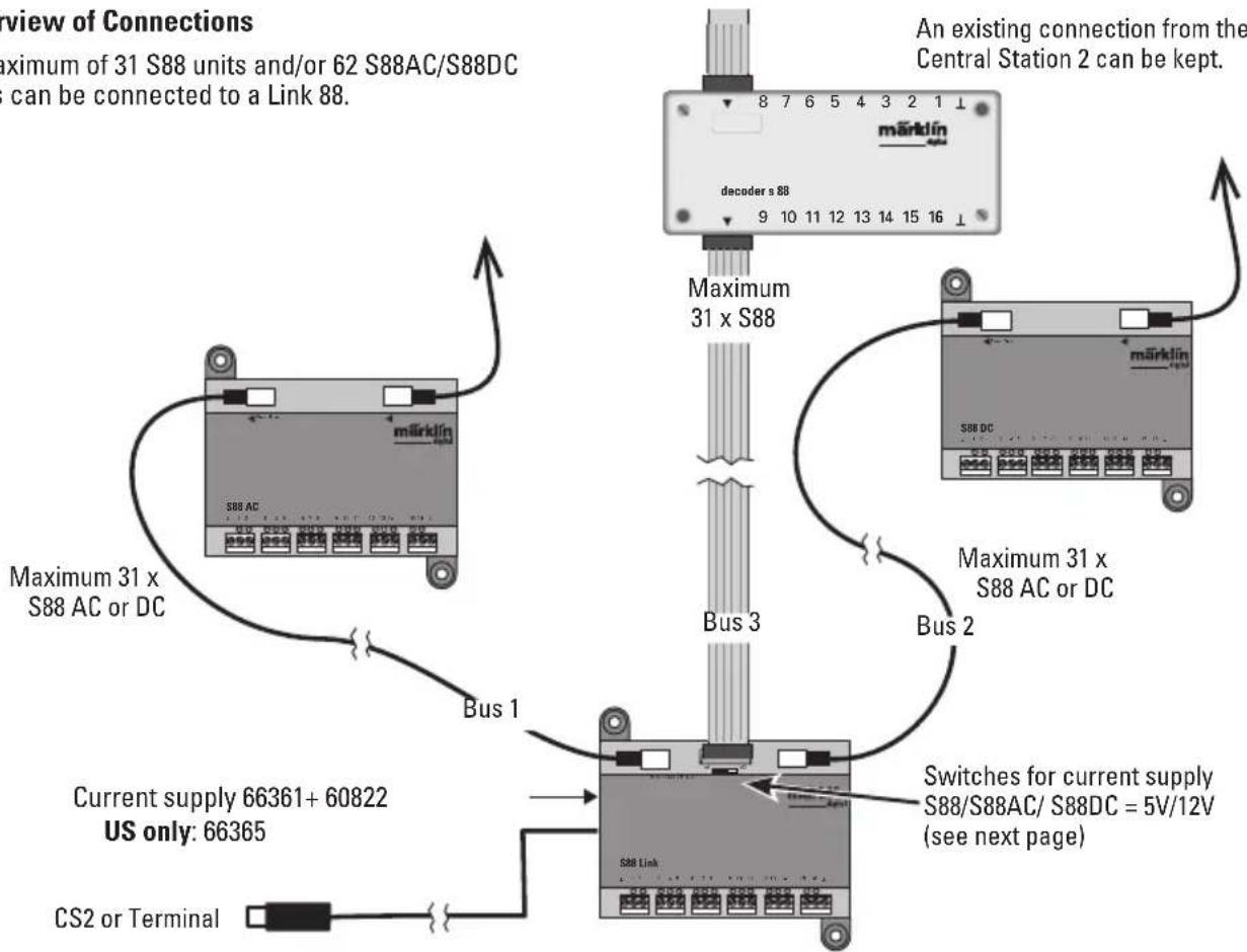
Overview of Connections
A maximum of 31 S88 units and/or 62 S88AC/S88DC units can be connected to a Link 88.
An existing connection from the S88 to the Central Station 2 can be kept.
flowchart
graph TD
    A["Current supply 66361+60822\nUS only: 66365"] --> B["Bus 1"]
    B --> C["S88 Link"]
    C --> D["Bus 2"]
    D --> E["Maximum 31 x S88 AC or DC"]
    E --> F["An existing connection from the Central Station 2 can be kept."]
    C --> G["Maximlín S88 DC"]
    G --> H["decoder s 88"]
    H --> I["8 7 6 5 4 3 2 1 ↑"]
    C --> J["Current Supply 66361+60822"]
    C --> K["CS2 or Terminal"]
    style A fill:#f9f,stroke:#333
    style B fill:#ccf,stroke:#333
    style C fill:#cfc,stroke:#333
    style D fill:#fcc,stroke:#333
    style E fill:#cff,stroke:#333
    style F fill:#ffc,stroke:#333
    style G fill:#fcf,stroke:#333
    style H fill:#cff,stroke:#333
    style I fill:#ffc,stroke:#333
    style J fill:#cfc,stroke:#333
    style K fill:#fcc,stroke:#333
Current Supply:
5volts in mixed operation of S88 and S88 AC/DC Märklin products (as shown in the illustration), as well as products of other makes.
12 volts only in conjunction with the S88 AC/DC. The susceptibility to interruptions is reduced with a 12 volt power supply.
PIN Assignment for the RJ45 Plug
| S88 Pin | Name Description | PIN RJ45 | ColorEIA/TIA 568A | |
| 1 DATA Readout Data 2 green | ||||
| 2 GND Ground for signals and voltage supply 3 white/orange | ||||
| 2 GND 5 white/blue | ||||
| 3 CLOCK Clock signal for the synchronization 4 blue | ||||
| 4 PS (LOAD) Load the data into the bus 6 orange | ||||
| 5 RESET Reset the input memory 7 white/brown | ||||
| 6 | +5V/+12V | Voltage supply for the feedback module | 1 | white/green |
| — | SHIELD | Cable shield, not connected | — | — |
Märklin assumes no liability for joint use of Märklin products and products of other makes.
We therefore urgently recommend that you check the PIN assignments of the RJ45 plug you may be using.
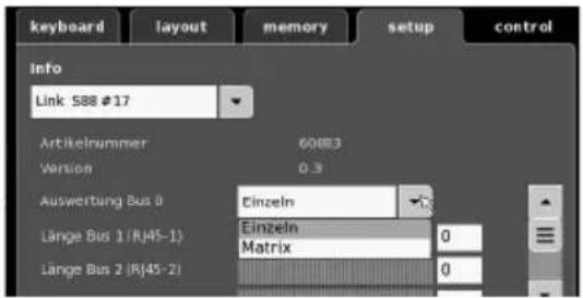
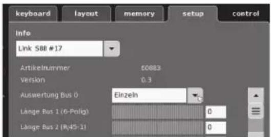
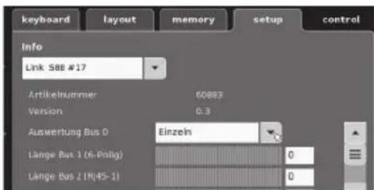
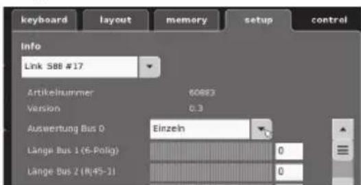
Configuration for the L88
The L88 must first be configured before using it for the first time. To do this go into the CS to setup/Info and with the tool symbol 🖼 go into the configuration mode. All of the following images are examples:
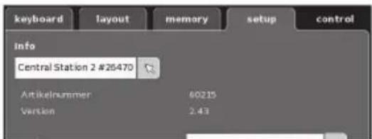
Open up Info
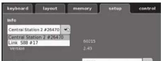
Select Link S88 #17.
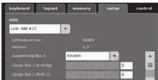
Now the individual data can be set..
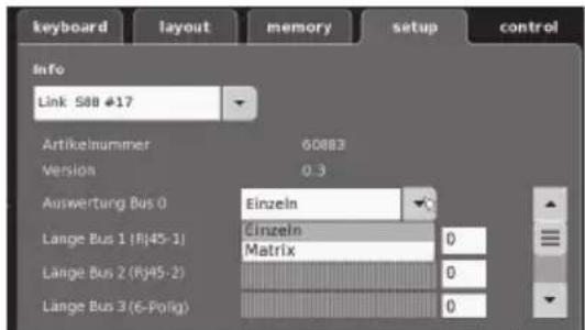
- Evaluation of Bus 0 (direct bus for the L88), Setting for individual units = 16 indicator contacts Setting for matrix = up to 64 button controllers
- Length of Bus 1-3 Here you enter how many S88 units are connected to each bus (max. 31).
- Cycle period for Bus 1-3 Enter query cycles for the S88 busses in milliseconds (ms) (min 10 ms - max. 1000 msm, factory setting 100 ms).
- Bit time for the S88 Set the cycle for the answer (factory setting 167 μs)
- Cycle period for (Link 88) Contacts 1 - 16 Query cycles for the Link contacts when used as track contacts 1 - 16.
- Cycle period for keyboard Query cycle when used as a keyboard (factory setting 67 ms).
- Columns for the keyboard Entering the columns (max. 8) for the keyboard matrix
- Rows for the keyboard Entering the rows (max. 8) for the keyboard matrix
Addresses for the Module:
The module automatically get an address when it is plugged in. You will find below the addresses for settings in the Central Station.
Contacts (track): 1-16
Button controller addresses: 101-164
Bus 1: 1001 -1496 (ex. 1005 = 1st module, Contact 5)
Bus 2: 2001 - 2496
Bus 3: 3001 - 3496
Examples of Settings on the Central Station:
Settings on the Central Station:
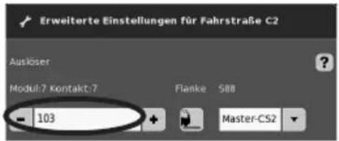
- Use as a track contact:
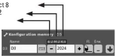
1.1 Use in the Memory (example)
Go into the Configuration mode
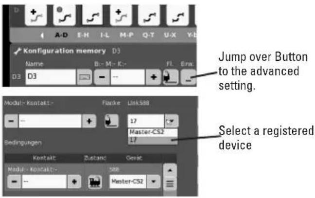
e.g. Contact 8
Modul 2
Bus 2
1.2 Use in the Layout (example)
Go into the Configuration mode and define the contact
Swapping Devices.
If a device swap becomes necessary, the new L88 can be switched to the previous device number. The switch takes place after the Link S88 registers in the CS at setup -Tool -Devices - edit. Enter the new Link S88 there with the previous device number and confirm this number. After that, the CS needs to be rebooted. All of the contacts will function as usual.
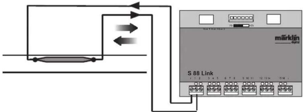
Sample Connections for the Different Feedback Contacts
Only one ground return is required for all track contacts.
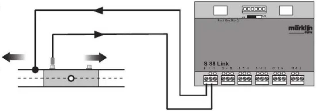
Connections to the Märklin H0 track system with the Circuit Track

= Direction of training back
Feedback is dependent on the direction of travel
flowchart
graph TD
    A["Device"] --> B["S 88 Link"]
    B --> C["Pin 1"]
    B --> D["Pin 2"]
    B --> E["Pin 3"]
    B --> F["Pin 4"]
    B --> G["Pin 5"]
    B --> H["Pin 6"]
    B --> I["Pin 7"]
    B --> J["Pin 8"]
    B --> K["Pin 9"]
    B --> L["Pin 10"]
    B --> M["Pin 11"]
    B --> N["Pin 12"]
    B --> O["Pin 13"]
    B --> P["Pin 14"]
    B --> Q["Pin 15"]
    B --> R["Pin 16"]
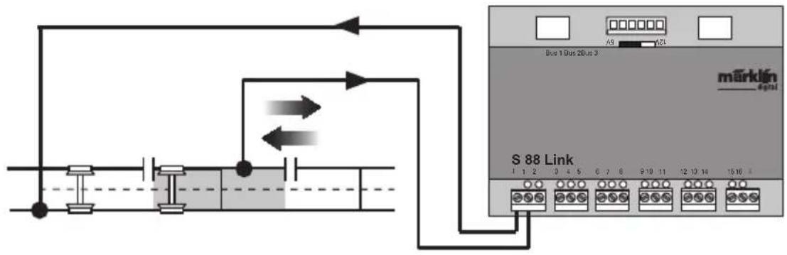
Connections to the Märklin H0 track system with Contact Tracks
Feedback is independent of the direction of travel
flowchart
graph TD
    A["Start"] --> B["Switch"]
    B --> C["Terminal Bus 1 Dus 2 Bus 3"]
    C --> D["Terminal Bus 2 L"]
    D --> E["Terminal Bus 3"]
    E --> F["Terminal Bus 4"]
    F --> G["Terminal Bus 5"]
    G --> H["Terminal Bus 6"]
    H --> I["Terminal Bus 7"]
    I --> J["Terminal Bus 8"]
    J --> K["Terminal Bus 9"]
    K --> L["Terminal Bus 10"]
    L --> M["Terminal Bus 11"]
    M --> N["Terminal Bus 12"]
    N --> O["Terminal Bus 13"]
    O --> P["Terminal Bus 14"]
    P --> Q["Terminal Bus 15"]
    Q --> R["Terminal Bus 16"]
    R --> S["Terminal Bus 17"]
    S --> T["Terminal Bus 18"]
    T --> U["Terminal Bus 19"]
    U --> V["Terminal Bus 20"]
    V --> W["Terminal Bus 21"]
    W --> X["Terminal Bus 22"]
    X --> Y["Terminal Bus 23"]
    Y --> Z["Terminal Bus 24"]
    Z --> AA["Terminal Bus 25"]
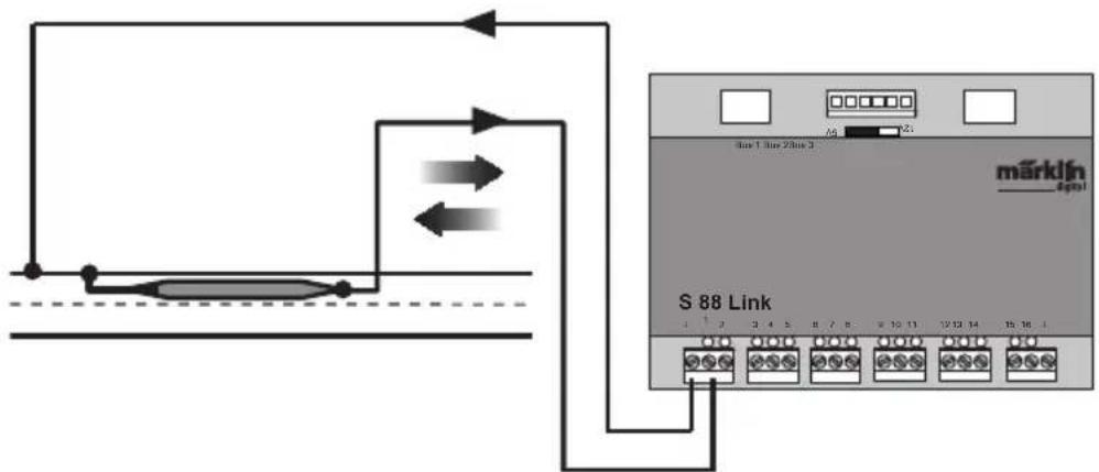
Connections to the Märklin H0 track system with Reed Switches
Feedback is independent of the direction of travel
flowchart
graph TD
    A["Microcontroller"] --> B["S 88 Link"]
    B --> C["Port 1"]
    B --> D["Port 2"]
    B --> E["Port 3"]
    B --> F["Port 4"]
    B --> G["Port 5"]
    B --> H["Port 6"]
    B --> I["Port 7"]
    B --> J["Port 8"]
    B --> K["Port 9"]
    B --> L["Port 10"]
    B --> M["Port 11"]
    B --> N["Port 12"]
    B --> O["Port 13"]
    B --> P["Port 14"]
    B --> Q["Port 15"]
Ground return is required per reed switch
Connections to two-rail track systems, independent of the gauge only with Reed Switches.
Feedback is independent of the direction of travel
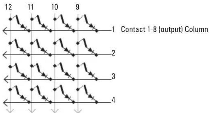
Use as a Button Matrix (Control Box):
If you want to use the L88 for a button matrix, then the following setting must be done.
A maximum of 64 button controllers (32 solenoid devices or 64 routes) can be supported by the setting Matrix. A 1N4148 diode per button is required for the setup. Pay attention to the installation direction.
Contact 9-16 (input) line
flowchart
graph TD
    A["1"] --> B["2"]
    B --> C["3"]
    C --> D["4"]
    style A fill:#f9f,stroke:#333
    style B fill:#f9f,stroke:#333
    style C fill:#f9f,stroke:#333
    style D fill:#f9f,stroke:#333
    subgraph "Contact 1-8 (output) Column"
        direction LR
        A --> B --> C --> D
        B --> C --> D
    end
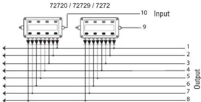
Connections for a Control Box
A maximum of 8 control boxes (Inputs 9 - 16) can be connected.
Now every button must be assigned to a route. Make sure, that the routes in the Memory are set for automatic operation.
The settings are done in the configuration mode for the Memory (see instructions for the Central Station). The assignment is done by means of the button ... in the advanced settings for a route.
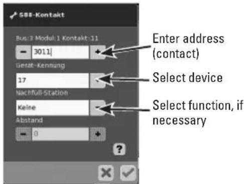
You first enter the address for the button (see table page 23).
After that enter the assigned device (here 17).
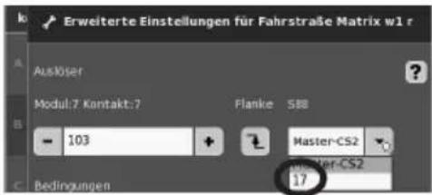
If everything has been entered correctly, confirm it with the green check mark. Store in memory along the way with the blue arrow on the display now appearing in the image. After that edit or process other routes or confirm with the green check mark and end the process.
Addresses the button (Example)
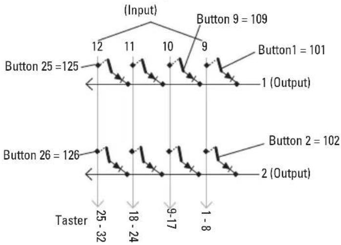
line
| Button | Value | | ---------- | ----- | | Button 25 | 125 | | Button 26 | 126 | | Button 9 | 109 | | Button 1 | 101 | | Button 2 | 102 | | Button 26 | 32 | | Button 2 | 8 |Address Table for the Buttons
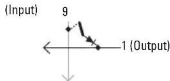
Please note, the diode must be installed in the blocking direction at the output.
Example Button 1: 9 output connected to input 1 is replaced by the address. 101.
| Output\Input | 9 10 | 11 12 | 13 14 | 15 16 | |||
| 1 101 109 | 117 | 125 1 | 33 141 | 149 | 157 | ||
| 2 102 110 | 118 | 126 1 | 34 142 | 150 | 158 | ||
| 3 103 111 | 119 | 127 1 | 35 143 | 151 | 159 | ||
| 4 104 112 | 120 | 128 1 | 36 144 | 152 | 160 | ||
| 5 105 113 | 121 | 129 1 | 37 145 | 153 | 161 | ||
| 6 106 114 | 122 | 130 1 | 38 146 | 154 | 162 | ||
| 7 107 115 | 123 | 131 1 | 39 147 | 155 | 163 | ||
| 8 108 116 | 124 | 132 1 | 40 148 | 156 | 164 |
kies Link S88#17
Vælg Link S88 #17,
Due to different legal requirements regarding electro-magnetic compatibility, this item may be used in the USA only after separate certification for FCC compliance and an adjustment if necessary.
Use in the USA without this certification is not permitted and absolves us of any liability. If you should want such certification to be done, please contact us – also due to the additional costs incurred for this.