
Lamington - Fireplace Klarstein - Free user manual and instructions
Find the device manual for free Lamington Klarstein in PDF.

| Product type | Electric fireplace |
| Brand | Klarstein |
| Model | Lamington |
| Power supply | 220-240 V ~ 50 Hz |
| Nominal heat output | 2.0 kW |
| Minimum heat output | 1.0 kW |
| Control type | Electronic room temperature control with weekly scheduling |
| Control options | Open window detection, operating time limitation |
| Heating modes | Low, high, automatic (timer) |
| Flame effect | Yes, adjustable to 4 brightness levels |
| Control panel | Touch + remote control |
| Remote control battery | CR2025 |
| Mounting | Permanent wall mounting |
| Minimum installation height | 300 mm |
| Recommended height for optimal view | 600 mm above floor |
| Safety distance to flammable materials | 1 meter |
| Overheat protection | Yes, with manual reset (disconnect for 15 min) |
| Glass cleaning | Dry or damp cloth, no abrasive products |
| Manufacturer's country of origin | Germany (Chal-Tec GmbH, Berlin) |
| Article numbers | 10038005, 10038006 |
Frequently Asked Questions - Lamington Klarstein
User questions about Lamington Klarstein
0 question about this device. Answer the ones you know or ask your own.
Ask a new question about this device
Download the instructions for your Fireplace in PDF format for free! Find your manual Lamington - Klarstein and take your electronic device back in hand. On this page are published all the documents necessary for the use of your device. Lamington by Klarstein.
USER MANUAL Lamington Klarstein
Note: The device is not suitable for use as a primary heat source.
INHALTSVERZEICHNIS
Produktdatenblatt 4
natural_image
Pure technical line drawing of a structural beam with evenly spaced supports (no text or symbols)natural_image
Diagram showing a horizontal line with two vertical supports and a close-up of a brick wall structure (no text or symbols)natural_image
Pure diagram of a beam with fixed supports and red arrows indicating direction, no text or symbols presentnatural_image
Technical line drawing of a rectangular electronic device with internal components and mounting holes (no text or symbols)natural_image
Technical line drawing of a server rack unit with ventilation slots and mounting bracket (no text or symbols)natural_image
Technical line drawing of a cabinet or enclosure with internal components and mounting brackets (no text or symbols)natural_image
Technical line drawing of a door panel with control panel and indicator lights, showing alignment and measurement lines (no text or symbols)natural_image
Symbol of a trash bin with crossed lines indicating no waste, and a solid black rectangle below (no text or labels)Congratulations on purchasing this device. Please read the following instructions carefully and follow them to prevent possible damages. We assume no liability for damage caused by disregard of the instructions and improper use. Scan the QR code to get access to the latest user manual and more product information.

CONTENTS
Product Data Sheet 24
Safety Instructions 25
Device Overview 26
Installation 27
Operation 34
Cleaning and Maintenance 37
Disposal Considerations 38
Manufacturer & Importer (UK) 38
TECHNICAL DATA
| Item number 10038005,10038006 | |
| Power supply 220-240 V ~ 50 Hz | |
| Power 2000 W |
PRODUCT DATA SHEET
| Model identifier(s): 10038005, 10038006 | ||||||
| Item Symbol Value Unit Item Unit | ||||||
| Heat output Type of heat input, for electric storage local space | heaters only | |||||
| Nominal heat output P | nom | 2.0 kW | manual heat | heat | charge control, with integrated thermostat | no |
| Minimum heat output (indicative) | P_min | 1.0 kW | manual heat | heat | charge control with room and/or outdoor temperature feedback | no |
| Maximum continuous heat output | P_max,c | 2.0 kW | electronic | heat | charge control with room and/or outdoor temperature feedback | no |
| Auxiliary electricity consumption fan assisted heat output no | ||||||
| At nominal heat output el | max | 0.000 kW | Type of heat | heat | output/room temperature control | |
| At minimum heat output el | min | 0.000 kW | single stage | heat | output and no room temperature control | no |
| In standby mode | el_sb | 0.000 | W | Two or more manual stages, no room temperature control | no | |
| with mechanic thermostat room temperature control | no | |||||
| with electronic room temperature control | no | |||||
| electronic room temperature control plus day timer | no | |||||
| electronic room temperature control plus week timer | yes | |||||
| Other control options | ||||||
| room temperature control, with presence detection | no | |||||
| room temperature control, with open window detection | yes | |||||
| with distance control option | no | |||||
| with adaptive start control | no | |||||
| with working time limitation | yes | |||||
| with black bulb sensor | no | |||||
| Contact details | Chal-Tec GmbH, Mühlenstraße 25, 10243, Berlin, Germany | |||||
SAFETY INSTRUCTIONS
- Before use, check the voltage information on the rating plate and only connect the device to sockets that correspond to the nominal voltage of the device.
- If the power cord is damaged, have it replaced by a trained professional.
- Do not place the fireplace directly under the mains socket.
- Keep a distance of one metre from combustible materials such as furniture, curtains or similar.
- Use the appliance out of the reach of children. Children may only operate the device under supervision.
- The appliance is intended for use in the home and similar environments only. It is not intended for commercial use.
- Do not use the device if it malfunctions or has been damaged in any way.
• Repairs may only be carried out by trained specialists. - Incorrectly or independently performed repairs pose a risk of injury.
- Do not run the power cord under carpets or rugs.
- Make sure that the power cord does not come into contact with sharp edges or hot surfaces.
- To prevent overheating, do not cover the fireplace.
- Do not use the appliance with an external timer, a remote controlled socket or any other device that automatically turns the fireplace on and off.
- Do not immerse the device in water or other liquids.
- Do not use the appliance near bathtubs, showers or swimming pools.
- Do not use the device outdoors.
- Do not use the device with wet hands.
- Do not use the appliance on or near hot surfaces
- Do not use the device with a damaged power cord.
- Before cleaning, unplug the appliance from the wall outlet and allow it to cool completely.
- Do not use abrasive cleaners for cleaning.
- Only use accessories that are expressly approved for this purpose by the manufacturer.
• Children from the age of 8 years and mentally, sensory and physically impaired persons may only use the device if they have been informed in detail about the functions and safety precautions by a supervisor responsible for them beforehand and understand the associated risks. - Make sure that children do not play with the appliance.
CAUTION
Risk of burns! Some parts of the appliance can become very hot.
Be careful not to burn yourself or your children with it.
DEVICE OVERVIEW
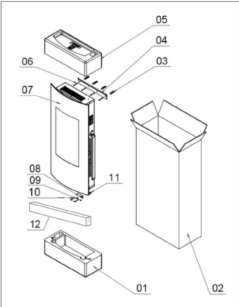
| No. | Description Quantity | No. | Description Quantity | |
| 1 | Lower fuse 1 7 Fireplace | 1 | ||
| 2 | Cardboard 1 8 Mounting | bracket 1 | ||
| 3 | Dowel 4 9 Screw (4 x 8 mm) | 2 | ||
| 4 | Wall mount 1 10 Screw (4 x 35 mm) | 2 | ||
| 5 | Top fuse 1 11 Dowel 2 | |||
| 6 | Screw (4 x 35 mm) | 4 | 12 Sponge strip 1 |
INSTALLATION
First steps
- Remove the unit from the packaging.
- Remove the packaging materials from the unit.
- Store the packaging materials in the packaging or dispose of them properly.
Before installation
- After unpacking, check all components for completeness and only then dispose of the packaging materials.
- The packaging material contains small parts that must be kept at a safe distance from small children.
- Before installation, open the packaging containing small parts such as screws, remove them all together and store them in a box so that the small parts do not get lost before installation.
Important installation instructions
General precautions must be taken when using electrical equipment to reduce the risk of fire, electric shock and injury. This includes the following:
- First remove the glass.
- Do not connect the appliance to the power supply until it has been properly mounted on the wall and you have read the entire operating instructions.
• Minimum distances must be respected. - When installing the unit, be careful not to damage concealed cables.
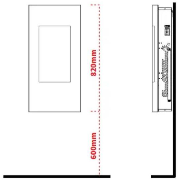
• Take care when drilling the holes. - This unit is intended for permanent wall mounting at a minimum height of 300 mm. The wall bracket must be mounted horizontally and the cable must be routed to the bottom right of the heater.
- For an optimal view of the fuel bed, installation at a height of 600 mm above the floor is recommended.
1. Wall installation
1

natural_image
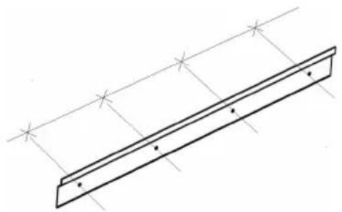
Pure technical line drawing of a beam supported by two parallel supports (no text or symbols)Select the location on the wall where you want to hang up the heater. Use the wall bracket (4) as a table template to draw a horizontal line with a spirit level. Mark 4 drill holes for the 4 anchoring screws.
Note: The holes are for mounting the heater and must be level so that the heater can be mounted properly and horizontally
2
natural_image
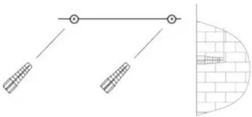
Diagram showing a mechanical linkage system with two springs and a vertical brick wall section (no text or symbols)Drill 4 holes with a diameter of 8 mm and a depth of 43 mm at the marked positions. Remove the dust from the drill holes and insert the dowels into the holes. Carefully tap the dowels into the wall with a hammer until they are aligned with the wall.
3
natural_image
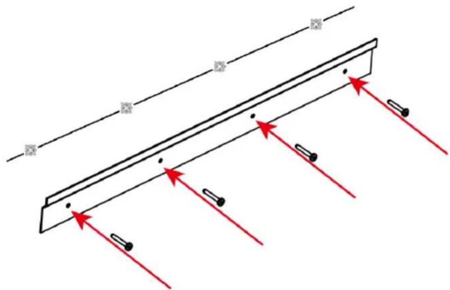
Pure diagram of a beam with fixed supports and red arrows indicating direction, no text or symbols presentSecure the wall bracket to the wall with the 4 anchoring screws.
4
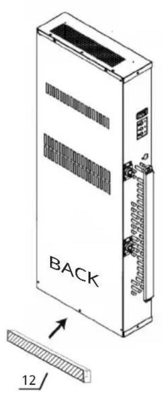
The sponge strip can be applied to the bottom position on the back the product before installation to reduce the resonance caused by the product and the wooden wall.
5
natural_image
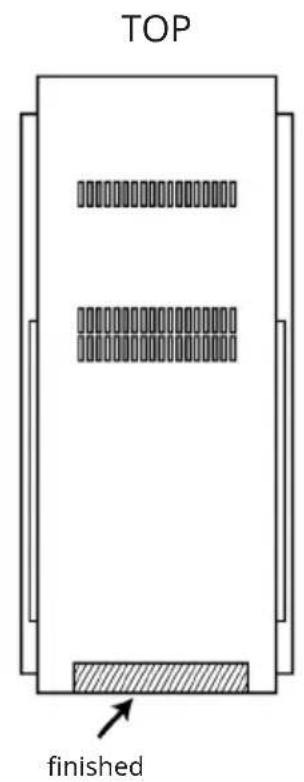
Technical line drawing of a rectangular electronic device with internal components and mounting holes (no text or symbols)Attach the mounting bracket (4) to the bottom of the unit with 2 short screws (3).
6
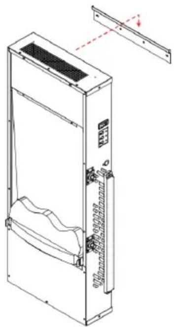
natural_image
Technical line drawing of a server rack unit with ventilation slots and mounting bracket (no text or symbols)Carefully lift the unit and attach it to the metal wall bracket. Do not release the unit until it is securely anchored.
7
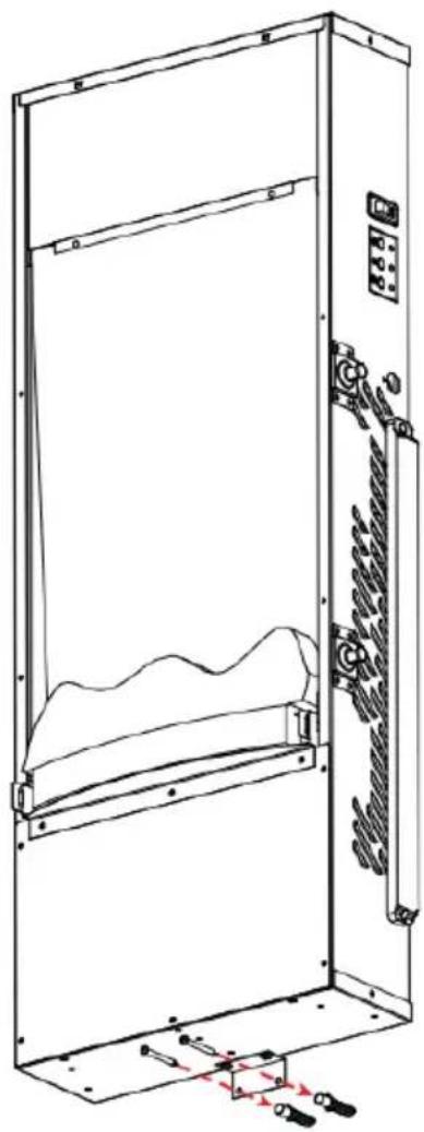
natural_image
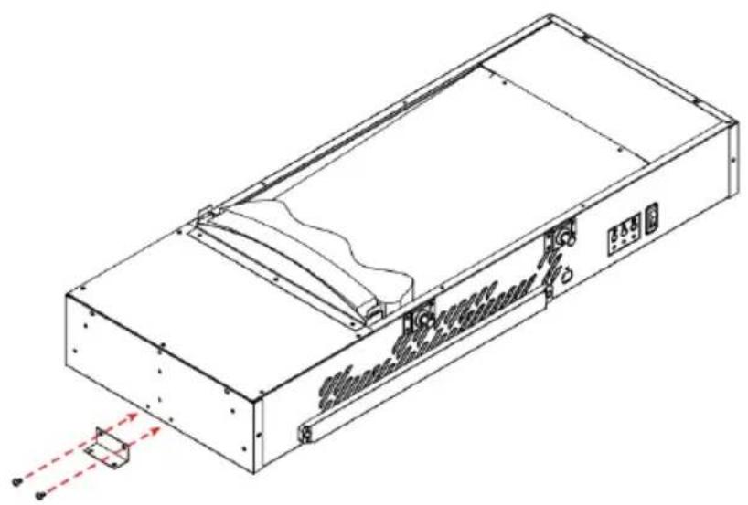
Technical line drawing of a cabinet or enclosure with internal components and mounting brackets (no text or symbols)Now mark the hole position for the fixing bracket. Carefully remove the unit from the cradle. Drill 2 holes 8 mm in diameter and 43 mm deep at the marked locations.
Remove the dust from the drill holes and insert the dowels into the holes.
Carefully tap the dowels into the wall with a hammer until they are aligned with the wall.
Now lift the unit again, attach it to the bracket and finally fix the bracket with the screws.
8
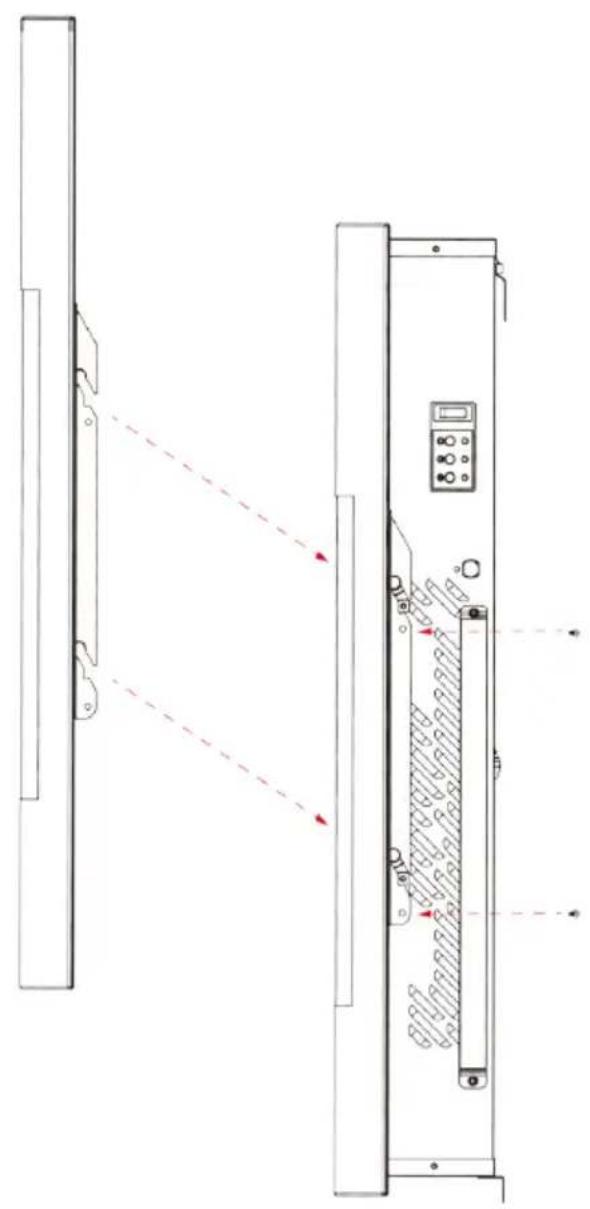
natural_image
Technical line drawing of a device with two vertical panels, one showing red dashed lines and arrows indicating alignment or measurement (no text or symbols present)Replace the front glass panel.
OPERATION
Commissioning
- The unit can be used as soon as it has been properly installed and connected to an earthed socket.
Notes on the operation
- Make sure that the circuit breakers for the power supply are switched on.
- The unit can be used with both the remote control and the touch control.
- Every time you adjust something with the remote control, the appliance makes a sound.
- When the backlight of the touchscreen is off, the unit can be activated and used with the remote control or by touching the touchscreen.
- The temperature setting can only be adjusted when the outdoor temperature is between 10 °C and 25 °C. The heating process depends on the temperature set by the user.
Power switch
 | When the power switch on the top of the unit is turned on, the unit beeps once, the backlight of the touch screen lights up and the unit is now in standby mode. As soon as the power switch is turned off, the power supply to the unit is interrupted. |
- First, the power switch on the upper right side of the unit must be switched on.
| Operation via control panel | |
 | Press this button once to activate the fire and flame effect. An orange indicator lights up to show that the unit is in operating mode. |
 | Press this button once to set the low heating level. Press this button twice to switch off the heating level. |
 | Press this button once to set the high heating level. Press this button twice to switch off the heating level. |
| Operation via remote control | |
 | Press this button once to activate the fire and flame effect. Room temperature, date, time and flame effect light up on the screen. If no button is pressed, the screen turns off after 15 seconds. Press any button to reactivate the screen. |
 | Press this button on the remote control once to switch between °C (Celsius) and °F (Fahrenheit). |
 | Press this button several times to adjust the flame brightness. There are 4 different brightness levels to choose from. |
 | This button has no function. |
 | Press this button to control the heating: low, high or off. |
 | Backlight button: Press the button once to change the light effect. Press again until the desired setting is reached. |
| Automatic heating mode (intelligent control) | |
| AUTO | Press this button once to activate the automatic heating mode according to your timer setting.1. If there is no timer setting for the selected day, the fire will be switched off.2. If the room temperature is higher than the set temperature, the heating is automatically deactivated.3. If the room temperature is 0-5 °C lower than the set temperature, the low heating level will be activated.4. If the room temperature is at least 5 °C lower than the set temperature, the high heating level will be activated. |
| Date and time setting(The setting is made via remote control) | |
 | Press this button once and then press the [+] or [-] button to set the current hour (0 - 23).Press this button again to set the minutes with the [+] and [-] buttons (from 00 - 59).Press the button again to set the date: Sunday - Saturday from left to right. Wait 5 seconds until the setting has been saved. |
| Temperature setting | |
| + | Press the [+] button to increase the temperature. |
| - | Press the [-] button to lower the temperature. |
| Timer setting | |
 | If you press this button for 3 seconds, the indicator flashes on the screen. |
| OK | Press this button to select the first day (set date: Sunday to Saturday). |
| Activate timer:First set the time at which the timer is to be activated. “ON” lights up on the screen.Press the [+] and [-] buttons to set the hour. Press the button “SET” afterwards.Then use the [+] and [-] buttons to set the minutes and press the button . The "ON" indicator goes out and "OFF" is displayed on the screen.Deactivate timer:Now set the time at which the timer is to be deactivated. OFF" lights up on the screen. Press the [+] and [-] buttons to set the hour. Press the button “SET” afterwards.Then use the [+] and [-] buttons to set the minutes and press the button “SET”. The "OFF" indicator switches off.Complete the timer setting:Press the button “SET”and press the buttons [+] and [-] to adjust the temperature.Press the OK button to exit the day setting. Repeat the steps mentioned in the sections "Activating the timer" and "Deactivating the timer" to set the timer for additional weekdays. When you have finished the setting, the display turns off. | |
Activate timer:
- First set the time at which the timer is to be activated. "ON" lights up on the screen.
- Press the [+] and [-] buttons to set the hour. Press the button "SET" afterwards.
- Then use the [+] and [-] buttons to set the minutes and press the button. The "ON" indicator goes out and "OFF" is displayed on the screen.
Deactivate timer:
- Now set the time at which the timer is to be deactivated. OFF" lights up on the screen. Press the [+] and [-] buttons to set the hour. Press the button "SET" afterwards.
- Then use the [+] and [-] buttons to set the minutes and press the button "SET". The "OFF" indicator switches off.
Complete the timer setting:
- Press the button "SET" and press the buttons [+] and [-] to adjust the temperature.
- Press the OK button to exit the day setting. Repeat the steps mentioned in the sections "Activating the timer" and "Deactivating the timer" to set the timer for additional weekdays. When you have finished the setting, the display turns off.
Notes:
- If the indicator does not light up on the screen, the timer setting for the selected date is invalid.
- If you do not press the OK button, the setting is saved for the current day only.
- Press the button for 5 seconds when the appliance is in standby mode to reset all timer and temperature settings to factory settings.
- If no button is pressed for 15 seconds, the backlight turn off.
Changing the battery of the remote control
- Replace an empty battery with a new CR2025 battery. Follow the instructions on the back of the remote control to insert the new battery.
Overheating protection
- This appliance is equipped with an overheating protection which is activated in case the appliance overheats (for example, due to blocked air vents). For safety reasons, the unit is not automatically reset.
- To reset the appliance, disconnect the appliance from the power supply for at least 15 minutes.
CLEANING AND MAINTENANCE
WARNING
Electrocution and fire hazard! Before cleaning or servicing the appliance, switch it off and disconnect the power cord from the wall socket. Maintenance should only be carried out by a qualified specialist.
Cleaning the glass panel
- Wait until the appliance has cooled down completely before cleaning it.
- Remove dust with a dry cloth.
- Remove fingerprints and other dirt with a clean, damp cloth.
- Do not use abrasive cleaners or sprays on the glass surface.
- Metal and painted metal parts should only be cleaned with a clean, damp cloth. Do not use abrasive cleaners or sprays to clean these surfaces.
DISPOSAL CONSIDERATIONS
natural_image
Symbol of a trash bin with crossed lines indicating no waste or discharge, and a solid black rectangle below (no text or labels)If there is a legal regulation for the disposal of electrical and electronic devices in your country, this symbol on the product or on the packaging indicates that this product must not be disposed of with household waste. Instead, it must be taken to a collection point for the recycling of electrical and electronic equipment. By disposing of it in accordance with the rules, you are protecting the environment and the health of your fellow human beings from negative consequences. For information about the recycling and disposal of this product, please contact your local authority or your household waste disposal service.
This product contains batteries. If there is a legal regulation for the disposal of batteries in your country, the batteries must not be disposed of with household waste. Find out about local regulations for disposing of batteries. By disposing of them in accordance with the rules, you are protecting the environment and the health of your fellow human beings from negative consequences.
MANUFACTURER & IMPORTER (UK)
Chal-Tec GmbH, Mühlenstraße 25, 10243 Berlin, Germany. Contact: info@electronic-star.de
Estimado cliente:
ÍNDICE
natural_image
Pure technical line drawing of a structural beam with supports and cross marks (no text or symbols)natural_image
Diagram showing a horizontal line with two vertical supports and a close-up of a brick wall structure (no text or symbols)natural_image
Pure diagram of a beam with red arrows indicating direction, no text or symbols presentnatural_image
Technical line drawing of a rectangular electronic device with internal components and mounting holes (no text or symbols)natural_image
Technical line drawing of a server rack unit with ventilation slots and mounting bracket (no text or symbols)natural_image
Technical line drawing of a cabinet or enclosure with internal components and mounting brackets (no text or symbols)natural_image
Technical line drawing of a server rack with control panel and indicator lights, showing no text or symbolsInterruptor principal
natural_image
Symbol of a trash bin with crossed lines indicating no waste or discharge, and a solid black rectangle below (no text or labels)Cher client, chère cliente,
SOMMAIRE
FICHE DE DONNÉES PRODUIT
1. Installation murale
1
natural_image
Pure technical line drawing of a beam supported by two parallel supports (no text or symbols)natural_image
Diagram showing a horizontal line with two vertical supports and a close-up of a brick wall structure (no text or symbols)natural_image
Pure diagram of a beam with fixed supports and red arrows indicating direction, no text or symbols presentnatural_image
Technical line drawing of a rectangular electronic device with internal components and mounting holes (no text or symbols)natural_image
Technical line drawing of a server rack unit with ventilation slots and mounting bracket (no text or symbols)natural_image
Technical line drawing of a server rack cabinet with internal components and mounting hardware (no text or symbols)natural_image
Technical line drawing of a device panel with red dashed arrows indicating direction, no text or symbols presentnatural_image
Symbol of a trash bin with crossed lines indicating no waste or discharge, and a solid black rectangle below (no text or labels)INDICE
natural_image
Pure technical line drawing of a structural beam with supports and cross marks (no text or symbols)natural_image
Diagram showing a horizontal line with two vertical supports and a close-up of a brick wall structure (no text or symbols)natural_image
Pure diagram of a beam with red arrows indicating direction, no text or symbols presentnatural_image
Technical line drawing of a rectangular electronic device with internal components and mounting points (no text or symbols)natural_image
Technical line drawing of a server rack unit with ventilation slots and mounting bracket (no text or symbols)natural_image
Technical line drawing of a server rack cabinet with internal components and mounting hardware (no text or symbols)natural_image
Technical line drawing of a server rack with control panel and indicator lights, showing no text or symbolsnatural_image
Symbol of a trash bin with crossed lines indicating no waste or discharge, and a solid black rectangle below (no text or labels)

- INHALTSVERZEICHNIS
- CONTENTS
- SAFETY INSTRUCTIONS
- CAUTION
- DEVICE OVERVIEW
- INSTALLATION
- First steps
- Before installation
- Important installation instructions
- Wall installation
- OPERATION
- Commissioning
- Notes on the operation
- Power switch
- Activate timer:
- Deactivate timer:
- Complete the timer setting:
- Notes:
- Changing the battery of the remote control
- Overheating protection
- CLEANING AND MAINTENANCE
- WARNING
- Cleaning the glass panel
- DISPOSAL CONSIDERATIONS
- MANUFACTURER & IMPORTER (UK)
- Estimado cliente:
- ÍNDICE
- Interruptor principal
- Cher client, chère cliente,
- SOMMAIRE
- Installation murale
- INDICE
Brand : Klarstein
Model : Lamington
Category : Fireplace