X2P RTH20B - Thermostat HONEYWELL - Free user manual and instructions
Find the device manual for free X2P RTH20B HONEYWELL in PDF.

User questions about X2P RTH20B HONEYWELL
0 question about this device. Answer the ones you know or ask your own.
Ask a new question about this device
Download the instructions for your Thermostat in PDF format for free! Find your manual X2P RTH20B - HONEYWELL and take your electronic device back in hand. On this page are published all the documents necessary for the use of your device. X2P RTH20B by HONEYWELL.
USER MANUAL X2P RTH20B HONEYWELL
RTH22B/RTHC22B (2H/2C conventional
or 2H/1C HP)
Installation and User Guide
text_image
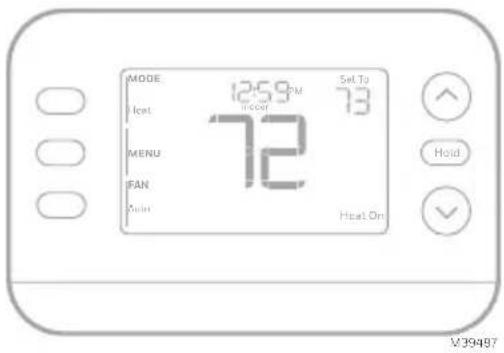
MODE 12:59 PM 73 Heat Floor MENU 72 FAN Joint Heat On V39487This document contains the following sections:
1) Installation and Wiring
2) Configuration
3) System Operation
4) Accent Piece Replacement
5) Troubleshooting
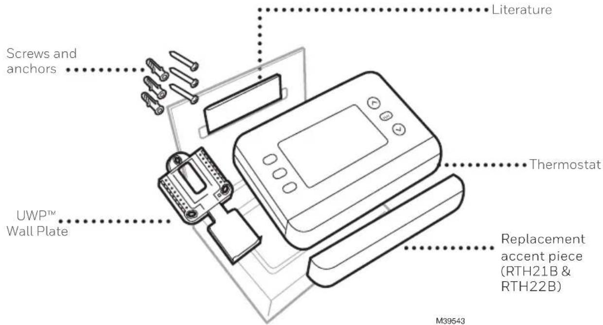
Package includes:
text_image
Literature Screws and anchors UWP™ Wall Plate Thermostat Replacement accent piece (RTH21B & RTH22B) M39543Tools you will need
Phillips screwdriver
Small flat head screwdriver
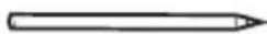
Pencil
Level
M36270
Tools you may need

Wire stripper
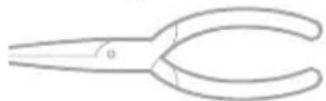
Needle-nose pliers
natural_image
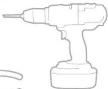
Line drawing of a handheld electric drill (no text or symbols)Drill and drill bit
READ AND SAVE THESE INSTRUCTIONS
Installation and Wiring
Removing the old thermostat
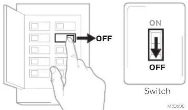
1 Turn power OFF.

To protect yourself and your equipment, turn off the power at the breaker box or switch that controls your heating/ cooling system. Some systems may have separate heating and cooling breakers.
text_image
OFF ON OFF Switch M39530Breaker box
2 Check that your system is off.

Change the temperature on your old thermostat to be above room temperature in heat mode or below it in cool mode. If you don't hear the system turn on within 5 minutes, the power is off. Note: If you have a digital thermostat that has a blank display, skip this step.
3 Remove the old thermostat's faceplate.
On most thermostats, you can take off the faceplate by grasping and gently pulling. Some thermostats may have screws, buttons, or clasps.
Do not remove any wires from your thermostat at this time!
text_image
75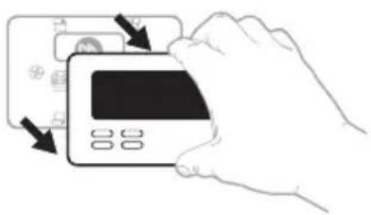
natural_image
Illustration of a hand inserting a credit card into a card slot (no text or symbols visible)4 Make sure there are no 120/240V wires.
Do you have thick black wires with wire nuts?

Is your thermostat 120V or higher?
If you answered yes to either of these questions, you have a line voltage system and the thermostat will not work.
5 Take a picture of how your wiring looks right now.
Be sure to include the letters next to the terminals where the wires are inserted. This will be a helpful reference when wiring your thermostat.
Tip: If the color of your wires has faded or if 2 terminals have the same wire color, use the wire labels provided in the package to label each wire.
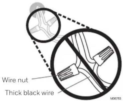
6 Make note of any jumpers
A jumper connects one terminal to another terminal. It may look like a small staple or even a colored wire.
text_image
Wire nut Thick black wire M36753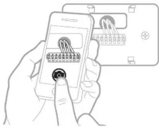
text_image
Illustration showing a hand holding a smartphone displaying a grid-based interface with icons, alongside a device labeled 'M' and a plus button.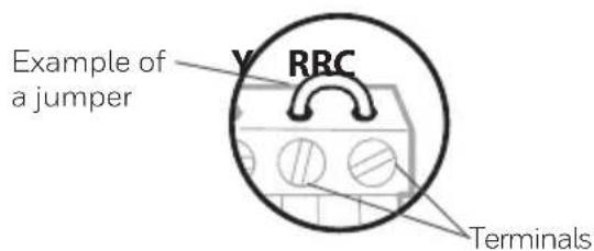
text_image
Example of a jumper Y RRC Terminals7 Record whether you have wires in the following terminals.
Do not include jumpers as a part of your count. This thermostat does not need jumpers.
Terminal Wire Color
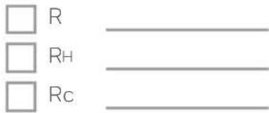
text_image
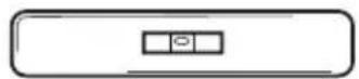
□ R □ RH □ Rc8 Write down the color of the wires.
Check mark the wires that are connected to terminals. Next to the check mark, write down the color of the wire. Do not include jumpers as a part of your count.
Check all that apply (Not all will apply):
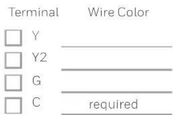
text_image
Terminal Wire Color □ Y ____ □ Y2 ____ □ G ____ □ C required
text_image
Terminal Wire Color □ A or L/A ____ □ O/B ____ □ W2 or AUX ____ □ E ____ □ W ____ □ K ____ M3955/19 Disconnect the wires and remove the old wall plate.
Use a screwdriver to release wires from terminals. Then, use a wire label to identify each wire as it's disconnected. The letter on the wire label should match the letter on the terminal.
Tip: To prevent wires from falling back into the wall, wrap the wires around a pencil.
natural_image
Hand holding a digital timer device with buttons and a display, showing no text or symbols on the device itself.
Installing the thermostat
text_image
Thermostat Screws UWP Wall Plate Anchors Wall M395461 Bundle and insert wires through the UWP.
Pull open the UWP and insert the bundle of wires through the back of the UWP.
Make sure at least 1/4-inch of each wire is exposed for easy insertion into the wire terminals.
2 Insert the wall anchors.
It is recommended that you use the wall anchors included in the box to mount your thermostat.
You can use the UWP to mark where you want to place the wall anchors.
a) Level the wall plate.
b) Mark the location of the wall anchors using a pencil.
c) Using a 3/16" bit, drill the holes.
d) Insert wall anchors.
e) Make sure anchors are flush with wall.

text_image
1/4" to 3/8" M39442A
text_image
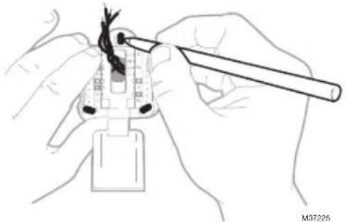
90° M372243 Set R-switch position and insert R-wire or wires.
Set the R-switch up or down based on your wiring notes in Step 7 of the section Removing the Old Thermostat.
natural_image
Illustration of hands using a tool to adjust cable or wire on a plug (no text or symbols visible)Insert wires into the inner holes of the terminals on the UWP. The tabs will stay down once the wire is inserted.
NOTE: Alternate wiring options are shown on the following pages
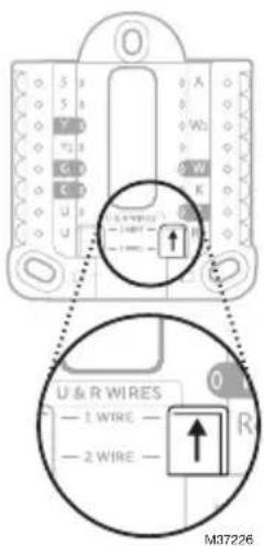
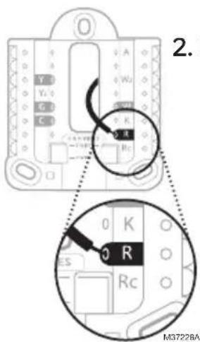
If you have 1 R-wire (R,Rh, or Rc)
text_image
U & R WIRES — 1 WIRE — — 2 WIRE — M37226- Set R-switch to the up position.
text_image
2. M3722BA- Insert your R-wire (R, Rh or Rc) into R-terminal.
or
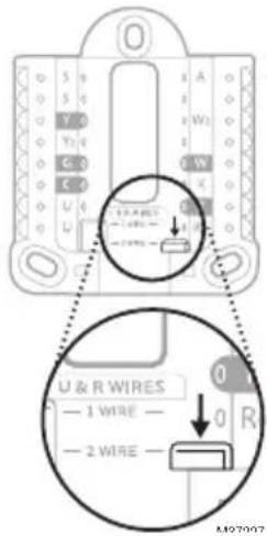
If you have 2 R-wires (R or Rh, and Rc)
text_image
U & R WIRES — 1 WIRE — — 2 WIRE — A W1 C3 C0 G R M97007- Set R-switch to the down position.
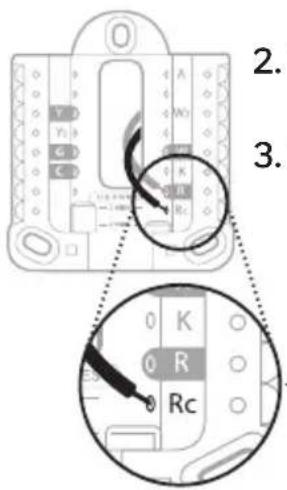
text_image
2. 3. 0 K 0 R Rc- Insert your Rc wire into Rc-terminal
- Insert your R or Rh wire into R-Terminal.
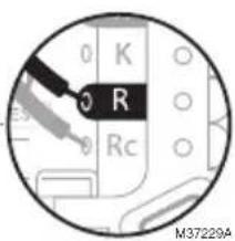
text_image
0 K R 0 Rc M37229A6
Wiring
Conventional Systems
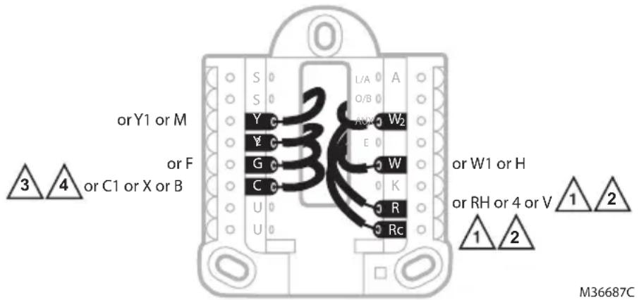
Alternate wiring (conventional systems)
If labels do not match terminals, connect wires as shown below (see notes below).
WIRING NOTES:
- If you must connect both R and Rc wires, set the R Slider Tab to the down position (2 wires).
- If your old thermostat had both R and RH wires, set the R Slider Tab to the down position (2 wires). Then connect the R wire to the Rc terminal, and the RH wire to the R terminal.
- If your old thermostat had only 1 C or C1 wire, connect it to the C terminal. If your old thermostat had 2 C or C1 wires, wrap each separately with electrical tape and do not connect them.
- C does not power the thermostat display or operations; batteries are always required.
text_image
orY1 or M or F or C1 or X or B 3 4 L/A A S S Y Y G C U U A O B W2 E W K R Rc or W1 or H or RH or 4 or V 1 2 1 2 M36687CHeat Pump
WIRING NOTES:
- Match each labeled wire with same letter on new thermostat.
- Insert the wires into the matching terminal.
NOTE: If you have difficulty inserting wires, you may have to press down the terminal push button next to the corresponding terminal. If the labels do not match the letters on the thermostat, see the diagram above.
text_image
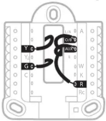
Y C Y2 G C L/A O/B AUX E W K R RcHeat Pumps
Alternate wiring (for heat pumps only)
WIRING NOTES:
- Keep R Slider Tab in the up position (1 wire).
- If your old thermostat had both V and VR wires, stop now and contact a qualified contractor for help.
- If your old thermostat had separate O and B wires, attach the B wire to the C terminal. If another wire is attached to the C terminal, stop now and contact a qualified contractor for help.
- If your old thermostat had Y1, W1 and W2 wires, stop now and contact a qualified contractor for help.
- C does not power the thermostat display or operations; batteries are always required.
- This model doesn't support the heat pump fault alert (L/A terminal). If this is desired, please contact a contractor for replacement model.
IMPORTANT: Do NOT
use W for heat pump applications. Auxiliary heat must wire to AUX or E.
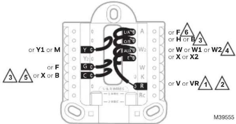
text_image
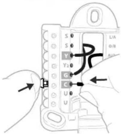
or Y1 or M 3 5 or F or X or B L/A O/B AUX E Y C G C C C U A R W I R E Rc W2 W K or F 6 or H or B 3 or W or W1 or W2 4 or X or X2 or V or VR 1 2 M395554 Connect wires to the UWP.
Refer to the notes you recorded on the chart during removal. Depress the tabs to put the wires into the inner holes of their corresponding terminals on the UWP (one wire per terminal) until it is firmly in place.
Gently tug on the wires to verify that they are secure.
Tip: If you need to release the wires again, push down the terminal tabs on the sides of the UWP.
text_image
S 0 S 0 Y 0 Y2 0 G 0 C 0 U 0 UThis wiring is just an example; yours may vary.
5 Confirm wiring matches snapshot.
Confirm wiring matches terminals from the photo you took during removal.
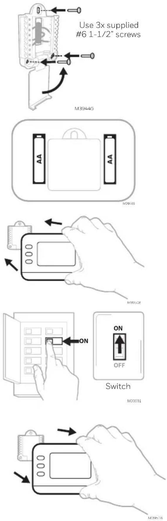
6 Mount the UWP and close the door.
Mount the UWP using the provided screws. Install all three screws for a secure fit on your wall. Close the door after you're finished.
7 Install batteries.
Insert two AA alkaline batteries in the back of the thermostat as shown.
8 Attach the thermostat.
Align the thermostat onto the UWP and firmly snap it into place.
9 Turn the power ON.
Turn on the power at the breaker box or switch that controls the heating/cooling system.
Breaker box
Battery Replacement
The display will alert you when the batteries are low and must be replaced. Remove the thermostat by pulling it away from its mount as seen at right.
Be sure to use fresh AA batteries and insert them as shown in Step 7. After inserting the new batteries, align the thermostat with the mounting plate and push gently until the thermostat snaps back into place as seen in Step 8.
Configuration
Set Time and Date
Once power is applied for installation, the date will start flashing.
Time
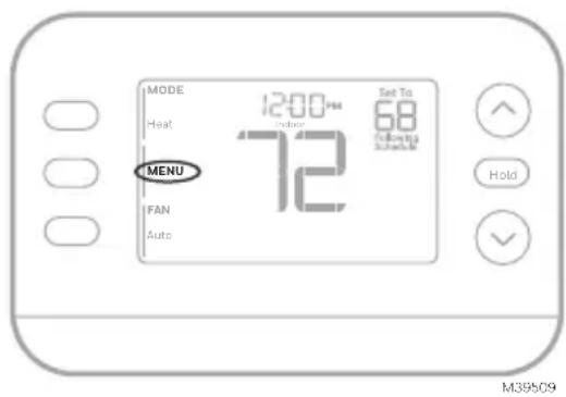
- Press MENU on the thermostat
- Press ↑ or ↓ to go to TIME and press SELECT
- Press ↑ or ↓ to choose 12 or 24 hour clock format and press NEXT
- Press ↑ or ↓ to adjust the hour and press NEXT.
- Press ↑ or ↓ to adjust the minute and press NEXT
Date
- Press MENU on the thermostat
- Press ↑ or ↓ to go to DATE and press SELECT
- Press ↑ or ↓ to choose YEAR and press NEXT
- Press ↑ or ↓ to choose MONTH and press NEXT
- Press ↑ or ↓ to choose DATE and press SAVE and then EXIT
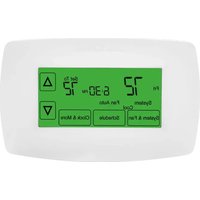
System Setup
On initial setup, the thermostat will enter the ISU menu after setting the time and date. If entering the ISU menu after initial setup, follow the steps below:
-
Press and hold the bottom left button and Up arrow ↑ button for 5 seconds to access the INSTALLER SETUP
-
The display shows the ISU number on the left and the ISU setting on the right.
When an ISU number is displayed, press or to change the setting for that ISU.
-
After choosing the correct setting for an ISU, press NEXT to advance to the next ISU setting.
-
To finish setup, press the SAVE & EXIT button; this will save your settings and return to the Home screen.
text_image
MODE 12:00 PM Set To Heat 72 68 Following Schedule MENU FAN Auto Hold M39509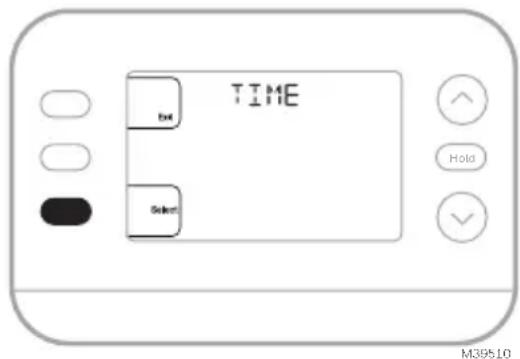
text_image
TIME BUT Select Hold M39510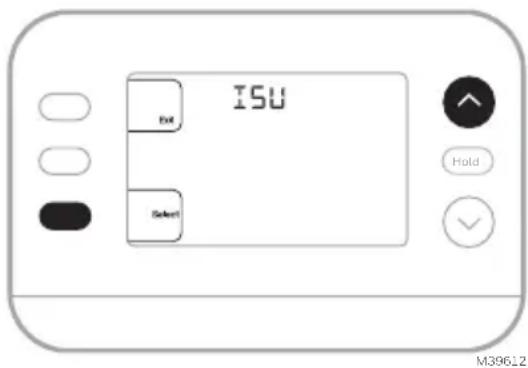
text_image
ISU Exit Select Hold M3962.2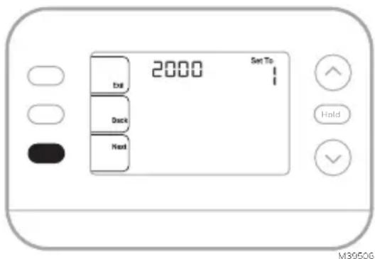
text_image
2000 Set To Exit Deck Next Hold M3950GInstaller Setup Options (ISU)
Depending on system settings, not all options may be available
| ISU ISU | Name ISU Options (factory default in bold) | ||
| 1040 | Scheduling Options (If you do not wish to set a schedule, use the default setting, then enter the Schedule Menu after completing setup and select Off) | 1 = 1 week (all days the same)2 = 5-2 Programmable (separate weekdays and weekend)(The RTH20B only has the 5-2 day setting)3 = 5-1-1 Programmable (separate Saturday and Sunday)4 = 7-Day Programmable (each day separate) | |
| 1050 | Temperature Indication Scale | F = Fahrenheit | C = Celsius (Default varies by model) |
| 2000 Heating System Type | 1 = Conventional Forced Air Heat2 = Heat Pump | 3 = Radiant Heat (Boiler)5 = None (Cool Only) | |
| If you are unsure what type of system you have, refer to your heating/cooling system equipment literature or call an HVAC professional. If you select the wrong system type, the thermostat will not operate the equipment as intended. | |||
| 2010 Heating Equipment Type | Conventional Forced Air Heat:1 = Standard Efficiency Gas Forced Air2 = High Efficiency Gas Forced Air3 = Oil Forced Air4 = Electric Forced Air | 5 = Hot Water Fan Coil(ISU 2010 not shown when 2000 = Heat Pump)Radiant Heat:9 = Hot Water Radiant Heat12 = Steam | |
| 2060 Reversing Valve O/B | 0 = O (O/B on Cool. O wire is connected to the O/B terminal and controls cooling.)1=B (O/B on Heat. B wire is connected to the O/B terminal and controls heat.)The literature that came with your heat pump equipment should indicate whether the reversing valve is energized in Heat or Cool mode | ||
| 2070 | Cool Stages/Compressor Stages | 0,1,2 (1 if 2000 = 2)Only 1 compressor stage available on RTH20B/RTHC20B and RTH21B/RTHC21B. Select the number of Stages. For heat pumps, only 1 stage is supported. | |
| 2071 | Heat Stages/Backup Heat Stages | Heat Stages:1,2 Backup Heat Stages: 0,1 (RTH21B/RTHC21B and RTH22B/RTHC22B) | |
| 2180 | Aux Backup Heat Type (for Heat Pump Systems) | 31=Electric Forced Air (This thermostat only supports electric backup heat. If your heat pump uses a gas or oil backup heat source, this thermostat should not be used.) | |
| 3000 System Changeover | 0 = Hidden (Manual only)1 = Enabled(Automatic available. In auto mode, the thermostat automatically switches between heating and cooling to maintain the desired indoor temperature. This option is not recommended if the outdoor temperature often stays below 50F [10C] during winter months.) | ||
| Continued on the next page | |||
Installer Setup Options (ISU)
continued from the previous page
| ISU ISU | Name ISU Options (factory default in bold) | ||
| 4090 Smart Response | 0=No1=Yes (Smart Response is a comfort setting. Heating or cooling equipment will turn on earlier, ensuring the indoor temperature will match the setpoint at the scheduled time.) | ||
| 4103 Min | mum Heat Setpoint | 32°F to 50°F Default 40°F0°C to 10.0°C Default 4.5 °CDo not set this lower than 40F/4.5C unless this is installed in a location where pipes are not at risk of freezing | |
| 7110 | Air Filter Replacement Reminder(Run time only counts the time that Heat, Cool or Fan are running) | 0 = Off1 = 10 Run Time Days2 = 20 Run Time Days3 = 30 Run Time Days4 = 45 Run Time Days5 = 60 Run Time Days6 = 90 Run Time Days7 = 120 Run Time Days8 = 150 Run Time Days9 = 30 Calendar Days | 10 =45 Calendar Days11 =60 Calendar Days12 =75 Calendar Days13 =3 Calendar Months14 =4 Calendar Months15 =5 Calendar Months16 =6 Calendar Months17 =9 Calendar Months18 =12 Calendar Months19 =15 Calendar Months |
| 14005 Idle screen selection | 0 - Minimum Information shown1 - Setpoint shown on idle screen2 - Maximum display information shown | ||
| 14010 Clock format 12/24 | |||
| 14015 Daylight Saving Time | 0=Off1=On | ||
System Operation
Settings
- Press the MODE button to cycle to the next available System mode
- Cycle through the modes until the desired System mode is displayed Available System modes vary by model and system settings.
System modes:
• AUTO
- HEAT
• COOL
• EM HEAT
• OFF

text_image
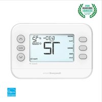
MODE Heat 12:00 PM Indoor Set To 68 FAN 72 Following Schedule MENU Auto HoldM39511
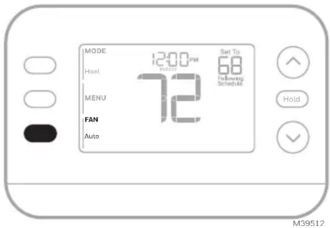
Fan Operation Settings
- Press the FAN button to cycle to the next available Fan mode
- Cycle through the modes until the desired Fan mode is displayed Available Fan modes vary with system settings.
Fan modes:
- AUTO: Fan runs only when the heating or cooling system is on
• ON: Fan is always on
• CIRC: Fan runs about 33% of the time to circulate air
text_image
MODE Heat 12:00 PM Indoor Set To 68 Following Schedule MENU 72 FAN Auto Hold M39512Program Schedule
You can program four time periods each day, with different settings for weekdays and weekends. We recommend using the presets shown in the table at right; these presets are designed to reduce your heating/cooling expenses.
WAKE: Set to the time you wake up and your desired temperature during the morning until you leave for the day.
AWAY: Set to the time you leave home and your desired temperature while you are away (usually an energy-saving temperature).
HOME: Set to the time you return home and your desired evening temperature until bedtime.
SLEEP: Set to your bedtime and your desired overnight temperature (usually an energy-saving temperature).
| Heat | Cool | |
| Wake(6:00 am) | 70° | 78° |
| Away(8:00 am) | 62° | 85° |
| Home(6:00 pm) | 70° | 78° |
| Sleep(10:00 pm) | 62° | 82° |
| Farenheit Deg. M36013 | ||
Adjusting program schedules
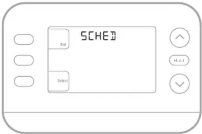
- Press MENU. Press ↑ or ↓ until SCHED is displayed.
- A square appears around ON or OFF in the display. If you want to use a schedule, press ↑ or ↓ to select ON. Press Select to edit the schedule or press EXIT to exit the menu.
- If editing the schedule, press SELECT to edit the day or days flashing in the display.
- The word Wake should be flashing. Press NEXT. Press ↑ or ↓ to turn this schedule period on or off. Note that selecting Off will disable this schedule period. Press NEXT.
- If the schedule period was set to ON, the time will be flashing. Press ↑ or ↓ to adjust the time for this period. Press NEXT.
- The Heat setpoint will be flashing. Press ↑ or ↓ to adjust the Heat setpoint for this period. Press NEXT.
- The Cool setpoint will be flashing. Press ↑ or ↓ to adjust the Cool setpoint for this period. Press NEXT.
- The display will show the next schedule period flashing. Repeat steps 4 – 7 for the Away, Home and Sleep schedule settings. After completing all schedule settings for the day(s) selected, repeat these steps for the other days.
- Press the SAVE & EXIT button at upper left.
When editing an existing schedule, you can advance to the setting you wish to change, edit that setting and press the SAVE & EXIT button to save changes.
Depending on what type of schedule the thermostat was set up for, days may be grouped or set individually.
text_image
SCHED Exit Select Hold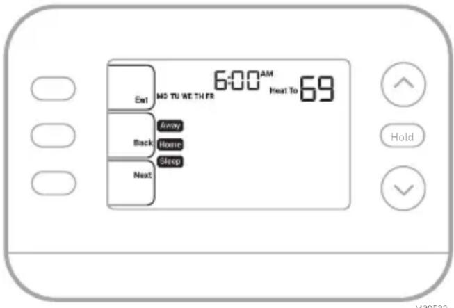
text_image
6:00 AM Heat To 69 Exit MO TU WE TH FR Back Away Home Sleep Next Hold V38532Smart Response Feature
This feature allows the thermostat to “learn” how long the furnace and air conditioner take to reach programmed temperature settings, so the temperature is reached at the time you set. For example:
Set the Wake time to 6 am and the temperature to 70°. The heat will come on before 6 am, so the temperature is 70° by the time you wake at 6. The message "Active Recovery" is displayed when the system is activated before a scheduled time period.
Program schedule override (Temporary)
- Press or to adjust the temperature.
- Once at the desired setpoint temperature, no further action is needed. The new setpoint temperature will be held until the next scheduled time period begins.
- Press the SAVE button or wait for the display to time out and return to the Home screen.
To cancel the Temporary Hold, press and release the HOLD button to cycle through the settings until CANCEL HOLD is selected.
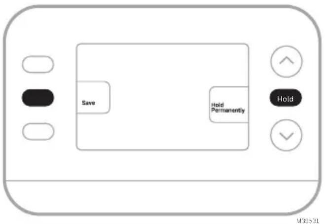
Program schedule override (Permanent)
- Press or to adjust the temperature.
- Once at the desired setpoint temperature, press and release the HOLD button to cycle through the settings until HOLD PERMANANTLY is selected.
- Press the SAVE button or wait for the display to time out and return to the Home screen.
To cancel the Permanent Hold, press and release the HOLD button to cycle through the settings until CANCEL HOLD is selected.
text_image
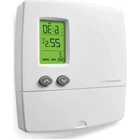
Save Hold Permanently Hold M38531Alerts
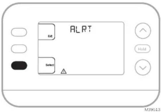
When an alert is active, an 📄 on will appear in the lower part of the display.
- Press MENU and use ↑ or ↓ until the alert is shown. Active alerts will be the first menu items shown.
- Press SELECT to display the alert number.
- An alert cannot be dismissed. If there is more than one active alert, pressing the NEXT button allows you to view any additional alert numbers. Press EXIT to return to the home screen.
Some alerts can be resolved by the homeowner, for example Replace Batteries. Other alerts may require a service call to the professional installer.
text_image
ALRT Bit Select Hold M39513
text_image
405 M39514| Alert Number Alert | Meaning |
| 405 Thermostat batteries are low. Replace batteries. | |
| 407 | Thermostat batteries are critically low. Replace batteries. |
| 170 Thermostat Memory Failure. Internal problem with the thermostat memory. | |
| 171 Set Time and Date. | |
| 173 Internal Sensor | Error. Issue with the built-in temperature sensor. |
Reminders
When a reminder is active, a icon will appear in the lower part of the display.
- Press MENU and use ↑ or ↓ until the active reminder is shown. Active alerts and reminders will be the first menu items shown.
- PressSELECT to display the reminder.
- Once selected you will see the reminder message in scrolling text. Press DISMISS to reset the reminder or press EXIT to return to the home screen without resetting the reminder.
If there is more than one active reminder, press the NEXT button to view all reminders which have not been reset.
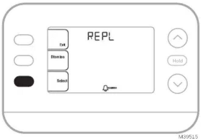
text_image
REPL Exit Dismiss Select Hold M39515Built-in Compressor Protection
Damage can occur if your system's compressor is restarted too soon after shutdown. This feature forces the compressor to wait for a few minutes before restarting. During the wait time, the display will show the message Waiting For Equipment under the room temperature reading.
When the safe wait time has elapsed, the message disappears, and the thermostat will show “Heat on” or “Cool on”.
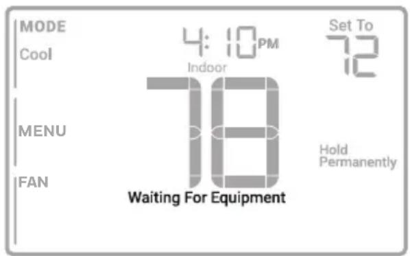
text_image
MODE Cool 4:10PM Indoor Set To 72 MENU 18 Hold Permanently FAN Waiting For EquipmentM39528
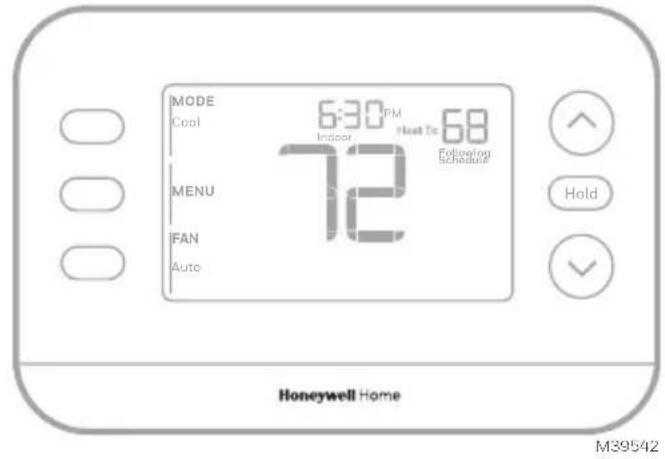
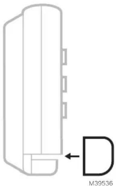
Accent Piece Replacement
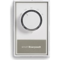
One white and one grey accent piece are provided with the RTH21B/RTHC21B and RTH22B/RTHC22B thermostats to accommodate different user preferences.
text_image
MODE Cool 6:30 PM Indoor Heat To 68 72 MENU FAN Auto Following Schedule Hold Honeywell Home M39542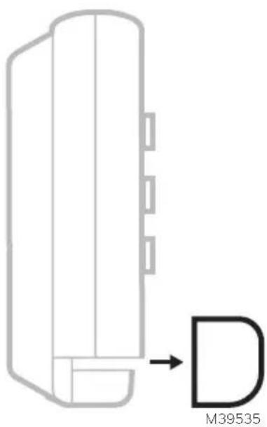
text_image
M39535To replace the accent piece, pull it away from the thermostat...
natural_image
Pure technical diagram of a mechanical component with no text or symbols...then snap the new one on.
See the video at:

text_image
QR code image containing encoded data, no visible human-readable textTroubleshooting
| Display is blank Make sure fresh AA alkaline batteries are correctly installed (see Step 7 in the section Intalling the Thermostat) | |
| Heating or cooling does not run | When running heat, display will show HEAT ON in lower right of displayWhen running cool, display will show COOL ON in lower right of displayIf display shows WAITING FOR EQUIPMENT under temperature reading, it is in compressor delay mode to protect the system. Wait 5 minutes to see if the thermostat makes a Heat or Cool callIf display does not indicate a call for Heat or Cool or WAITING FOR EQUIPMENT, verify the mode setting, temperature setpoint and room temperatureIf the Up or Down arrow is pressedUpper left of display shows mode settingUpper right shows setpointCenter of display shows room temperatureIf the issue persistsCheck circuit breaker and reset if necessaryMake sure power switch at heating & cooling system is onMake sure furnace door is closed securely |
| Heat or Aux Heat runs with Cooling | Verify there is not a wire attached to W for heat pump systems.See Wiring sectionFor heat pump applications the reversing valve is energized in Heat on some heat pumps and Cool for other heat pumps.Verify that ISU 2060 is set correctlyVerify that no wires are shorted. Look for exposed sections of wire at the UWP |
| Heat or Aux heat runs with no call for heat or cooling | Verify display does not indicate HEAT ON, COOL ON or AUX HEAT ONVerify there is not a wire attached to W for heat pump systems.See Wiring section.Verify that no wires are shorted. Look for exposed sections of wire at the UWP |
| Cannot change setpoint to desired setting | Verify the mode setting (Heat, Cool, Auto, or Em Heat in upper left of display)The setting ranges for these modes are:Heat or Em Heat: 32 °F to 90 °F (0 °C to 32.0 °C)Cool: 50 °F to 99 °F (10.0 °C to 37.0 °C)If the setpoint can be adjusted, but not to the full range shown above, the thermostat may be configured for a maximum heat or minimum cool setpoint to restrict settings that are energy inefficient. |
| WAITING FOR EQUIPMENT shown in display under room temperature | The compressor protection feature is engaged. Wait a few minutes for the system to safely restart to avoid damaging the compressor. |
Notes
Notes
Notes
Regulatory Information
FCC REGULATIONS
47 CFR § 15.19 (a)(3)
This device complies with part 15 of the FCC Rules. Operation is subject to the following two conditions:
1 This device may not cause harmful interference, and
2 This device must accept any interference received, including interference that may cause undesired operation.
47 CFR § 15.21 (USA only)
Changes or modifications not expressly approved by the party responsible for compliance could void the user's authority to operate the equipment.
47 CFR § 15.105 (b)
See https://customer.resideo.com/en-US/support/residential/codes-and-standards/FCC15105/Pages/default.aspx for additional FCC information for this product.
IC REGULATIONS
RSS-GEN
This device contains licence-exempt transmitter(s)/receiver(s) that comply with Innovation, Science and Economic Development Canada's licence-exempt RSS(s). Operation is subject to the following two conditions:
1 This device may not cause interference.
2 This device must accept any interference, including interference that may cause undesired operation of the device.
1-year Limited Warranty
For Warranty information go to Honeywellhome.com/support

CAUTION: ELECTRICAL HAZARD
Can cause electrical shock or equipment damage. Disconnect power before beginning installation.

CAUTION: EQUIPMENT DAMAGE HAZARD
Compressor protection is bypassed during testing. To prevent equipment damage, avoid cycling the compressor quickly.

CAUTION: MERCURY NOTICE
If this product is replacing a control that contains mercury in a sealed tube, do not place the old control in the trash. Contact your local waste management authority for instructions regarding recycling and proper disposal.

CAUTION: ELECTRONIC WASTE NOTICE
The product should not be disposed of with other household waste. Check for the nearest authorized collection centers or authorized recyclers. The correct disposal of end-of-life equipment will help prevent negative consequences for the environment and human health.
FCC statement available at: https://customer.resideo.com/en-US/support/residential/codes-and-standards/FCC15105/Pages/default.aspx
Customer Assistance
For assistance with this product, please visit honeywellhome.com
Or call Resideo Customer Care toll-free at 1-800-633-3991

resideo
Resideo Technologies Inc.
Scottsdale, AZ 85254
www.resideo.com 33-00688EFS-03 L.Y. Rev. 11-24
The Honeywell Home trademark is used under license from Honeywell International, Inc. This product is manufactured by Resideo Technologies, Inc. and its affiliates.
© 2024 Resideo Technologies, Inc.

text_image
Black and white barcode image with vertical lines and a central dot33-00688EFS-03
Honeywell Home

Thermostat programmable X2P RTH20B/RTHC20B (1H/1C) RTH21B/RTHC21B (1H/1C) RTH22B/RTHC22B (2H/2C HP conventionnel ou 2H/1C HP)
natural_image
Line drawing of a handheld electric drill (no text or symbols)Perceuse et mèche
LISEZ ET CONSERVEZ CES INSTRUCTIONS
natural_image
Illustration of a hand holding a smartphone displaying a grid-based interface with icons, next to an electronic device (no text or symbols visible)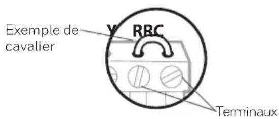
text_image
Exemple de cavalier RRC Terminauxtext_image
□ R □ RH □ Rctext_image
Diagram showing a hand holding a device with labeled buttons and arrows indicating action or change.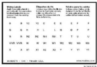
text_image
Wing Labels Apply Chinese writing lists to with all the appropriate federal documentation as you removed from the writing worklist. B Y2 Y2 C E E F F G H H L O O P P A R RC RC RH1 RH1 T U U VWR WWR W W1 W1 W2 W2 W3 W3 X X X1 X1 X2 X2 Y Y Y1 Y1 in-160579 - 544 - P### 100. www.risidec.com N281008text_image
1/4° to 3/8"natural_image
Illustration of hands using a tool to adjust or install wires on a circuit board (no text or symbols visible)text_image
0 K 0 R 0 Rc M37229ACâblage
text_image
Y G C L/A O/B AUX E W K R Rctext_image
S 0 S 0 Y 0 Y2 0 G 0 C 0 U 0 Unatural_image
Diagram of a battery pack with two side batteries labeled 'AA' on one side and one side, no text or symbols present.natural_image
Line drawing of a hand holding a handheld device with arrows indicating motion (no text or symbols)natural_image
Line drawing of a hand holding a handheld device with arrows indicating motion (no text or symbols)Configuration
text_image
TIME Select Hold M3B51Dtext_image
ISU Exit Select Hold M396L2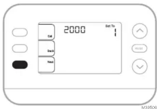
text_image
2000 Set To Call Back Next Hold M39506text_image
MODE 12:00 PM Set To 20.0 Inside Following Schedule Heat MENU 22.0 FAN Auto HoldMF39511
text_image
MODE 12:00 PM Set To Indoor 20.0 Following Schedule Heat MENU 22.0 FAN Auto HoldMF39512
text_image
6:00 AM MO TU WE THFR Heat To 20s Exit Back Next Anny Home Shoot HoldMF39532
text_image
Save Hold Permanently Hold M30531text_image
ALRT txt Select Hold M39513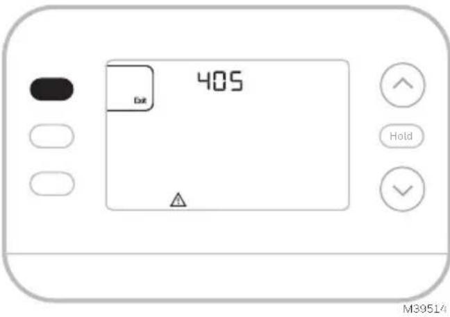
text_image
405 Dot Hold M39514text_image
REPL Exit Distress Select HoldM39515
text_image
MODE Cool 4:10 PM Indoor Set To 22.5 MENU 26.5 Hold Permanently FAN Circ Waiting For EquipmentMF39528
text_image
MODE Cool 6:30 PM Indoor Heat To 20.0 MENU 22.5 FAN Auto Following Schedule Hold Honeywell HomeMF39542
natural_image
Pure diagram of a mechanical component with an arrow pointing to a labeled part (no text or symbols)natural_image
Pure technical line drawing of a mechanical component with no text or symbolstext_image
QR code image containing encoded data, no visible human-readable textDépannage
47 CFR § 15.19 (a)(3)
47 CFR § 15.21 (USA uniquement)
https://customer.resideo.com/en-US/support/residential/codes-and-standards/
FCC15105/Pages/default.aspx
Resideo Technologies Inc.
Scottsdale, AZ 85254
33-00688EFS-03 L.Y. Rev. 11-24
© 2024 Resideo Technologies, Inc.

text_image
Barcode image containing encoded digital information33-00688EFS-03
Honeywell Home

Termostato programable X2P
RTH20B/RTHC20B (1H/1C)
RTH21B/RTHC21B (1H/1C)
RTH22B/RTHC22B (2H/2C convencional o
2H/1C HP)
natural_image
Line drawing of a handheld electric drill (no text or symbols)
Pinzas de punta
Taladro y broca
natural_image
Illustration of a hand inserting a credit card into a card slot (no text or symbols visible)natural_image
Illustration of a hand holding a smartphone displaying an electrical connector, with no visible text or symbols on the device itself.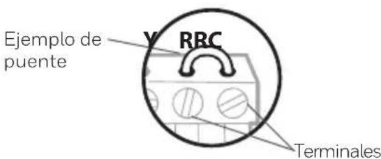
text_image
□ R □ RH □ Rcnatural_image
Hand holding a digital timer device with buttons and a close-up of the screen (no text or symbols visible)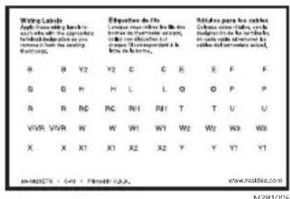
text_image
Wing Labels Apply the following key to such as: The appropriate federal documentation or you remains from the setting Routure. B Y2 Y2 C E E F F G H H L L O P P A B RC RC RH1 RH1 T U U VWR VWR W W W1 W1 W2 W2 W3 W3 X X X1 X1 X2 X2 Y Y Y1 Y1 in-160575 - 441 - 49441 USA. M/281005text_image
1/4" to 3/8" M39442A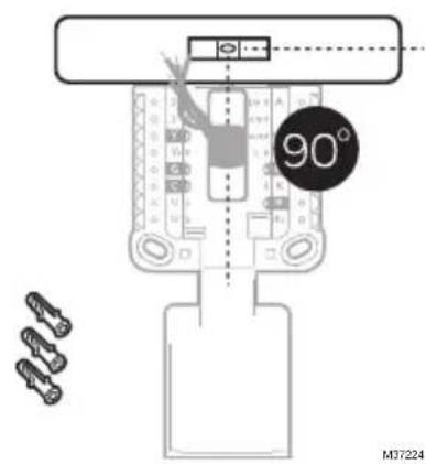
text_image
90° M37224natural_image
Illustration of hands using a tool to adjust cable or wire on a plug (no text or symbols visible)text_image
Y G C A W K R Rc 0 K 0 R Rctext_image
0 K 0 R 0 Rc M37229ACableado
text_image
Y C G C Y2 O/B AUX E W K R Rc L/A 0 0 0 0 0 0 0 0 0 0 0 0 0Bomba de calor
text_image
S 0 S 0 Y Y₂ 0 G 0 C 0 U 0 Unatural_image
Diagram of a battery pack with two AA batteries, no text or symbols presentnatural_image
Line drawing of a hand holding a handheld device with arrows indicating motion (no text or symbols)natural_image
Line drawing of a hand holding a handheld device with arrows indicating action (no text or symbols)Configuración
text_image
ISU Hold M28022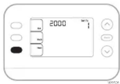
text_image
2000 3m F1 4m 5m 6m 7m 8m 9m 10m 11m 12m 13m 14m 15m 16m 17m 18m 19m 20m 21m 22m 23m 24m 25m 26m 27m 28m 29m 30m 31m 32m 33m 34m 35m 36m 37m 38m 39m 40m 41m 42m 43m 44m 45m 46m 47m 48m 49m 50m 51m 52m 53m 54m 55m 56m 57m 58m 59m 60m 61m 62m 63m 64m 65m 66m 67m 68m 69m 70m 71m 72m 73m 74m 75m 76m 77m 78m 79m 80m 81m 82m 83m 84m 85m 86m 87m 88m 89m 90m 91m 92m 93m 94m 95m 96m 97m 98m 99m 100mtext_image
MODE 12:00 PM Set to 20.0 Indoor Following Schedule Heat MENU 22.0 IFAN Auto Hold MS39511text_image
MODE 12:00 PM Set To 20.0 Heat Indoor Following Schedule MENU 22.0 FAN Auto Hold MS39512Programar horario
text_image
SCHED Set Select Hold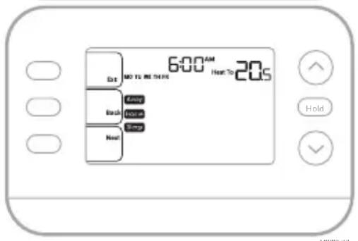
text_image
6:00 AM Hot To 20s Dot NO TO MORE Back Home Next Holdtext_image
Save Hold Permanently Hold M39531text_image
ALRT Exit Select Hold M39513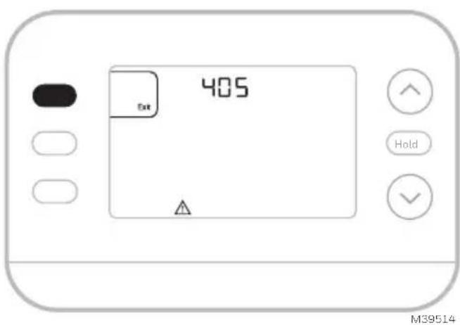
text_image
405 Exit Hold M39514text_image
REPL Exit Dismiss Select Hold M39515text_image
MODE Cool 4:10 PM Indoor Set To 22.5 MENU 26.5 Hold Permanently FAN Circ Waiting For EquipmentMS39528
text_image
MODE Cool 6:30 PM Indoor Host To 20.0 MENU 22.5 FAN Auto Following Schedule Hold Honeywell HomeMS39542
natural_image
Pure diagram of a mechanical component with no text, numbers, or symbolsnatural_image
Pure technical line drawing of a mechanical component with no text or symbolstext_image
QR code image containing encoded data, no visible human-readable text47 CFR § 15.19 (a)(3)
Resideo Technologies Inc. Scottsdale, AZ 85254
www.resideo.com 33-00688EFS-03 L.Y. Rev. 11-24

text_image
Barcode image with black and white vertical bars, no visible text or symbols beyond the pattern33-00688EFS-03
© 2024 Resideo Technologies, Inc.