RTH11B - Thermostat HONEYWELL - Free user manual and instructions
Find the device manual for free RTH11B HONEYWELL in PDF.

User questions about RTH11B HONEYWELL
0 question about this device. Answer the ones you know or ask your own.
Ask a new question about this device
Download the instructions for your Thermostat in PDF format for free! Find your manual RTH11B - HONEYWELL and take your electronic device back in hand. On this page are published all the documents necessary for the use of your device. RTH11B by HONEYWELL.
USER MANUAL RTH11B HONEYWELL
Installation and User Guide
text_image
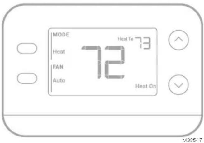
MODE Heat FAN Auto 72 Heat To 73 Heat On M39517This document contains the following sections:
1) Installation and Wiring
2) Configuration
3) System Operation
4) Troubleshooting
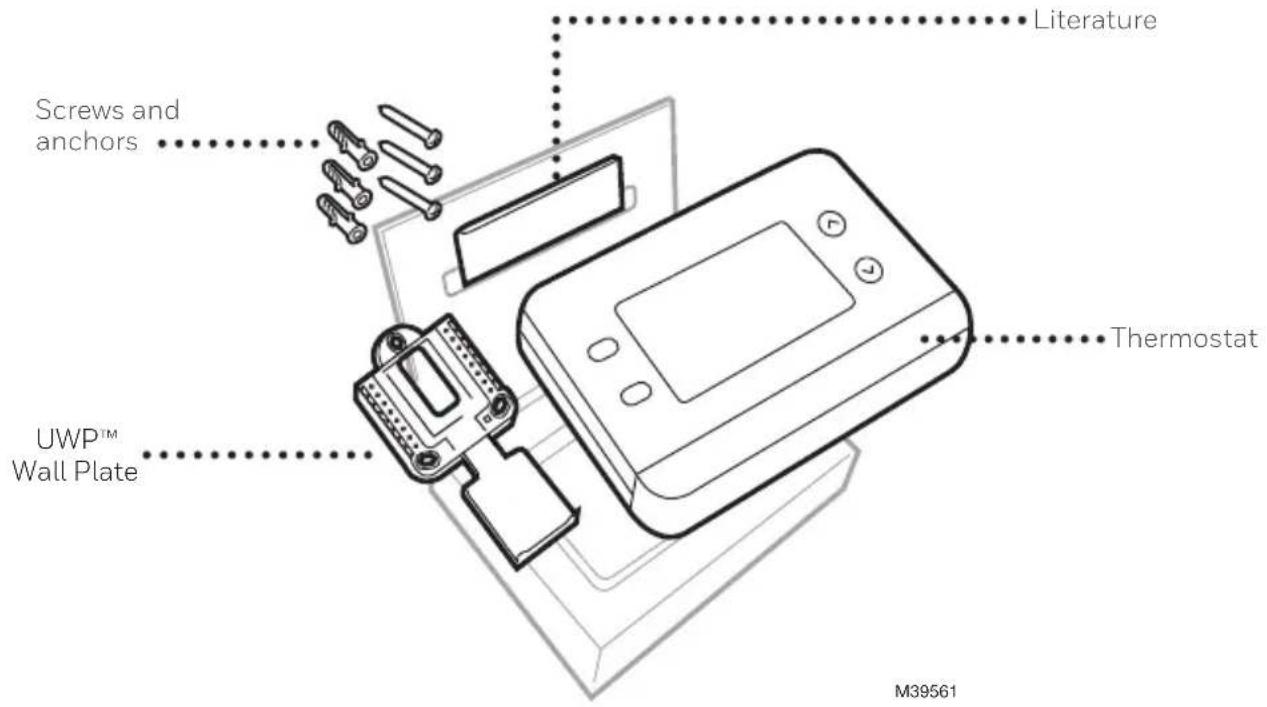
Package includes:
text_image
Literature Screws and anchors UWP™ Wall Plate Thermostat M39561Tools you will need
Phillips screwdriver
Small flat head screwdriver
Pencil
Level
M36270
Tools you may need

Wire stripper
Needle-nose pliers
natural_image
Line drawing of a handheld electric drill (no text or symbols)Drill and drill bit
READ AND SAVE THESE INSTRUCTIONS
Installation and Wiring
Removing the old thermostat
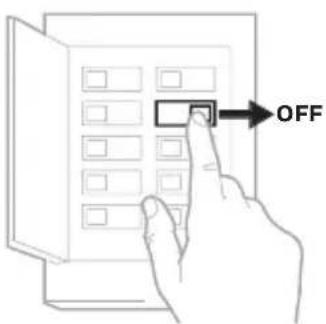
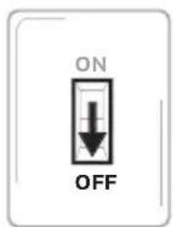
1 Turn power OFF.

To protect yourself and your equipment, turn off the power at the breaker box or switch that controls your heating/ cooling system. Note that some systems may have separate heating and cooling breakers.
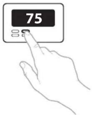
2 Check that your system is off.

Change the temperature on your old thermostat to be above room temperature in heat mode or below it in cool mode. If you don't hear the system turn on within 5 minutes, the power is off. Note: If you have a digital thermostat that has a blank display, skip this step
3 Remove the old thermostat's faceplate.
On most thermostats, you can take off the faceplate by grasping and gently pulling. Some thermostats may have screws, buttons, or clasps.
Do not remove any wires from your thermostat at this time!
text_image
OFFBreaker box
text_image
ON OFFSwitch M38590
text_image
75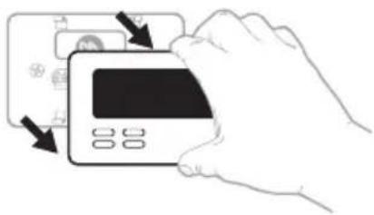
natural_image
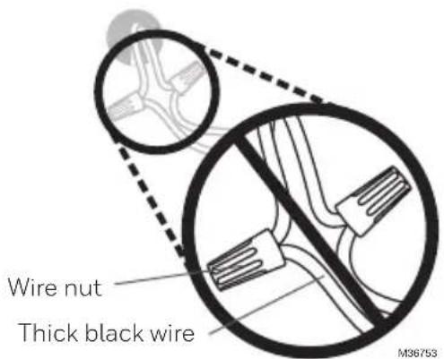
Illustration of a hand inserting a credit card into a card (no text or symbols visible)4 Make sure there are no 120/240V wires.
Do you have thick black wires with wire nuts?

Is your thermostat 120V or higher?
If you answered yes to either of these questions, you have a line voltage system and the thermostat will not work.
text_image
Wire nut Thick black wire M367535 Take a picture of how your wiring looks right now.
Be sure to include the letters next to the terminals where the wires are inserted. This will be a helpful reference when wiring your thermostat.
Tip: If the color of your wires has faded or if 2 terminals have the same wire color, use the wire labels provided in the package to label each wire.
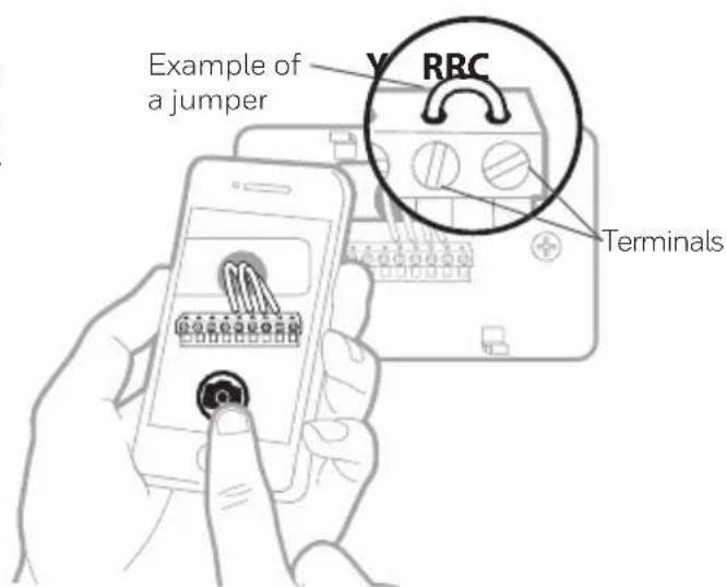
6 Make note of any jumpers
A jumper connects one terminal to another terminal. It may look like a small staple or even a colored wire.
text_image
Example of a jumper RRC Terminals7 Record whether you have wires in the following terminals.
Do not include jumpers as a part of your count. This thermostat does not need jumpers.
Terminal Wire Color
text_image
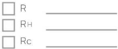
□ R □ RH □ Rc8 Write down the color of the wires.
Check mark the wires that are connected to terminals. Next to the check mark, write down the color of the wire. Do not include jumpers as a part of your count.
Check all that apply (Not all will apply):
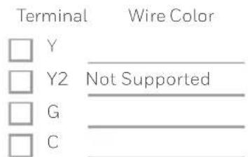
Important: The X1N is for single-stage systems only. If unsupported wires are used, the thermostat will not operate the equipment as intended.
text_image
Terminal Wire Color □ Y □ Y2 Not Supported □ G □ C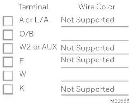
text_image
Terminal Wire Color □ A or L/A Not Supported □ O/B ____ □ W2 or AUX Not Supported □ E Not Supported □ W ____ □ K Not Supported M395669 Disconnect the wires and remove the old wall plate.
Use a screwdriver to release wires from terminals. Then, use a wire label to identify each wire as it's disconnected. The letter on the wire label should match the letter on the terminal.
Tip: To prevent wires from falling back into the wall, wrap the wires around a pencil.
natural_image
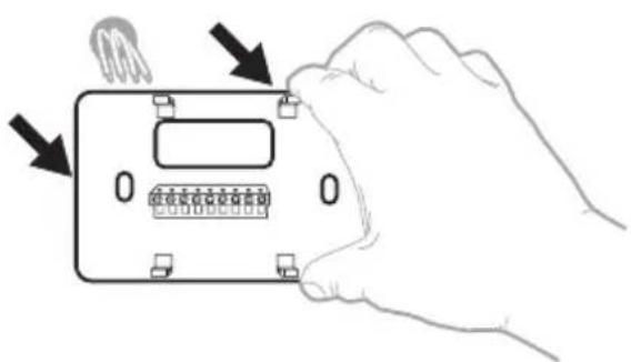
Hand holding a device with a grid and indicator lights, no text or symbols visible
1 Bundle and insert wires through the UWP.
Pull open the UWP and insert the bundle of wires through the back of the UWP.
Make sure at least 1/4-inch of each wire is exposed for easy insertion into the wire terminals.
2 Insert the wall anchors.
It is recommended that you use the wall anchors included in the box to mount your thermostat.
You can use the UWP to mark where you want to place the wall anchors.
a) Level the wall plate.
b) Mark the location of the wall anchors using a pencil.
c) Using a 3/16" bit, drill the holes.
d) Insert wall anchors.
e) Make sure anchors are flush with wall.
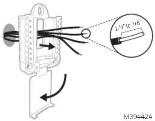
text_image
1/4" to 3/8" M39442A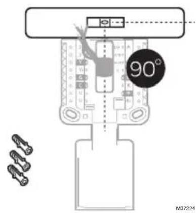
text_image
90° M372243 Set R-switch position and insert R-wire or wires.
Set the R-switch up or down based on your wiring notes in Step 7 in Removing the old thermostat.
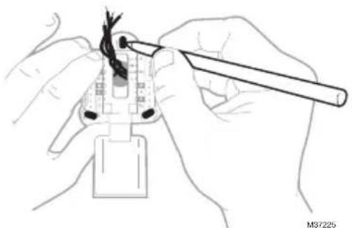
natural_image
Illustration of hands using a tool to adjust cable or wire on a plug (no text or symbols visible)Insert wires into the inner holes of the terminals on the UWP. The tabs will stay down once the wire is inserted.
Various wiring options are shown on the following pages
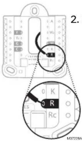
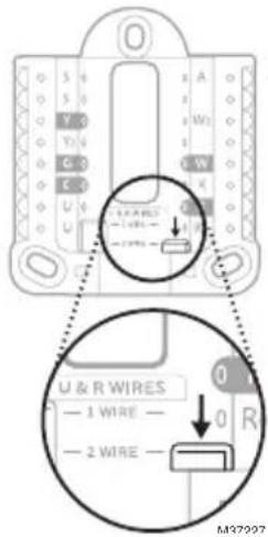
If you have 1 R-wire (R,Rh, or Rc)

text_image
U & R WIRES — 1 WIRE — — 2 WIRE — M37226- Set R-switch to the up position.
text_image
2. M37228A- Insert your R-wire (R, Rh or Rc) into R-terminal.
or
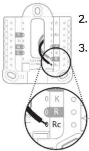
If you have 2 R-wires (R or Rh, and Rc)
text_image
U & R WIRES — 1 WIRE — — 2 WIRE — M37207- Set R-switch to the down position.
text_image
2. 3. 0 K 0 R Rc- Insert your Rc wire into Rc-terminal
- Insert your R or Rh wire into R-Terminal.
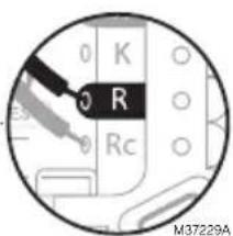
text_image
0 K 0 R 0 Rc M37229AWiring
If labels do not match terminals, connect wires as shown below.
Conventional Systems
Alternate wiring (for conventional systems)
WIRING NOTES:
- If you must connect both R and Rc wires, set the R Slider Tab to the down position (2 wires).
- If your old thermostat had both R and RH wires, set the R Slider Tab to the down position (2 wires). Then connect the R wire to the Rc terminal, and the RH wire to the R terminal.
- If your old thermostat had only 1 C or C1 wire, connect it to the C terminal. If your old thermostat had 2 C or C1 wires, wrap each separately with electrical tape and do not connect them.
- C does not power the thermostat display or operations; batteries are always required.
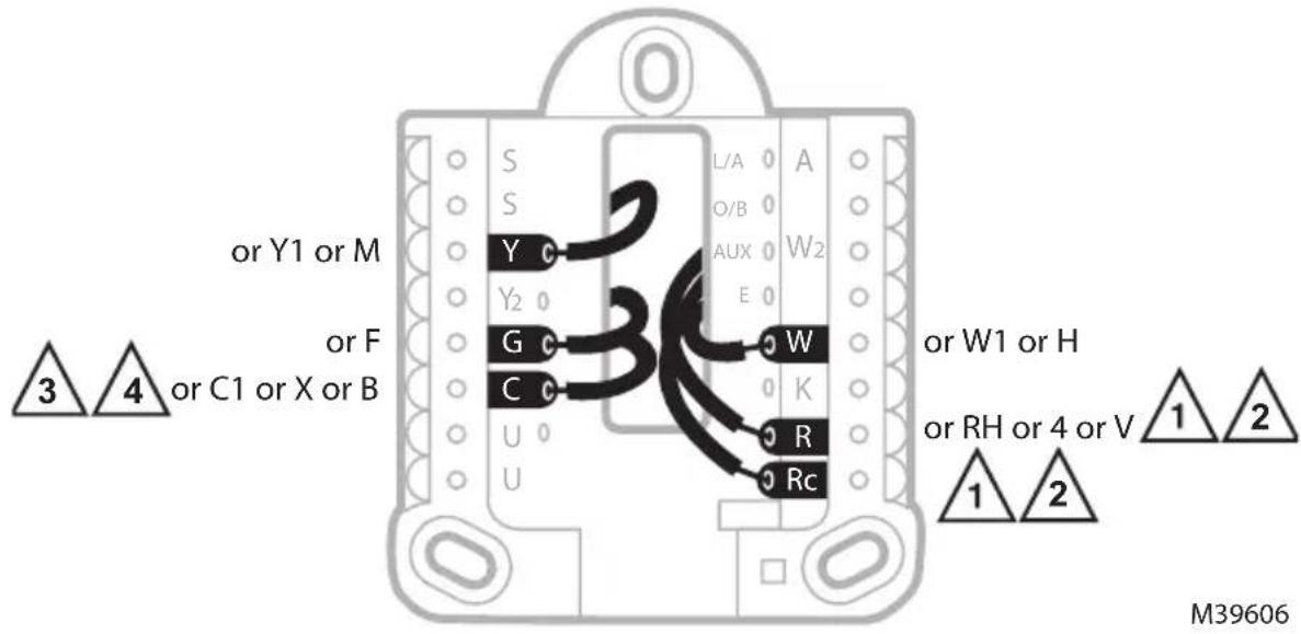
text_image
or Y1 or M or F or C1 or X or B 3 4 S Y G C U U L/A O/B AUX W2 E W K R Rc or W1 or H or RH or 4 or V 1 2 1 2 M39606Heat Pumps
Alternate wiring (for heat pump systems only)
WIRING NOTES:
- Keep R Slider Tab in the up position (1 wire).
- If your old thermostat had both V and VR wires, stop now and contact a qualified contractor for help.
- If your old thermostat had separate O and B wires, attach the B wire to the C terminal. If another wire is attached to the C terminal, stop now and contact a qualified contractor for help.
- If the O/B connection is used the thermostat will not support W, Aux/W2 or E wires.
- C does not power the thermostat display or operations; batteries are always required.
- This model does not support the heat pump fault alert (L/A terminal). If this is desired, please contact a contractor for replacement model.
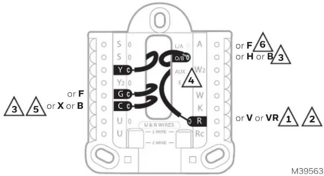
text_image
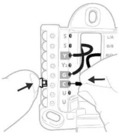
3 or F 5 or X or B or F or X or B or V or VR 1 2 M395634 Connect wires to the UWP.
Refer to the notes you recorded on the chart during removal. Depress the tabs to put the wires into the inner holes of their corresponding terminals on the UWP (one wire per terminal) until it is firmly in place.
5 Confirm wiring matches snapshot.
Confirm wiring matches terminals from the photo you took during removal.
6 Mount the UWP and close the door.
Mount the UWP using the provided screws. Install all three screws for a secure fit on your wall. Close the door after you're finished.
text_image
S 0 S 0 Y 0 Y2 0 G 0 C 0 U 0 U L/A Ø/B AUDThis wiring is just an example; yours may vary.

text_image
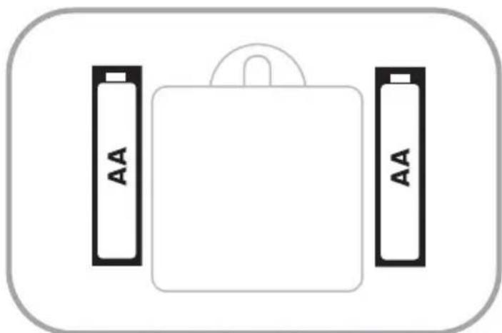
Use 3x supplied #6 1-1/2" screws M394457 Install batteries.
Insert two AA alkaline batteries in the back of the thermostat as shown.
natural_image
Simple diagram of a battery pack with two side batteries labeled 'AA' (no text or symbols on the battery itself)M39489
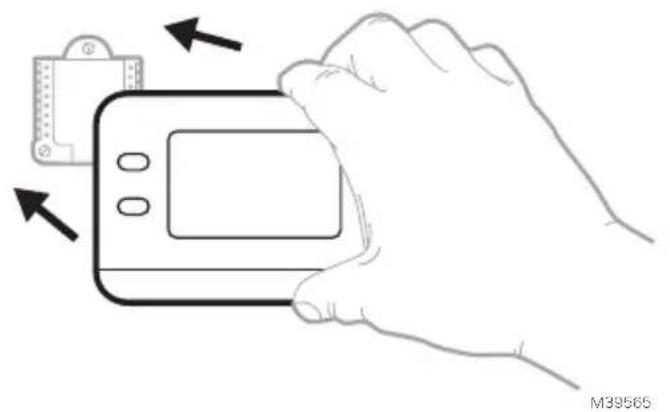
8 Attach the thermostat.
Align the thermostat onto the UWP and firmly snap it into place.
natural_image
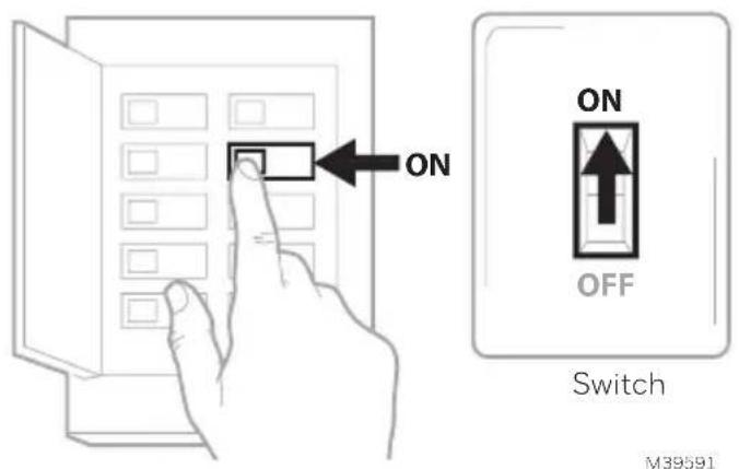
Line drawing of a hand holding a handheld device with arrows indicating movement or change (no text or symbols)9 Turn the power ON.
Turn on the power at the breaker box or switch that controls the heating/cooling system.
text_image
ON ON OFF Switch M39591Breaker box
Battery Replacement
The thermostat's display will let you know when the batteries are low and must be replaced. Remove the thermostat by pulling it away from its mount as seen at left below.

natural_image
Line drawing of a hand holding a handheld device with arrows indicating motion (no text or symbols)
natural_image
Simple diagram of a battery pack with two side batteries labeled 'AA' (no text or symbols beyond labels)Be sure to use fresh AA batteries and insert them as shown in the diagram at right above.
After inserting the new batteries, align the thermostat with the mounting plate and push gently until the thermostat snaps back into place as seen in Step 8 above.
Configuration
System Setup
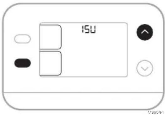
On initial setup, the thermostat will enter the ISU menu. If entering the ISU menu after initial setup, follow the steps below:
- Press and hold the bottom left button and Up arrow ↑ button for 5 seconds to access the INSTALLER SETUP (ISU)
- The ISU number is on the left. The ISU setting is on the right.
When an ISU number is displayed, press or to change the setting. - After choosing the correct setting for an ISU, press NEXT to advance to the next ISU setting.
- To finish setup, press the DONE button.
text_image
ISU V300/MI
text_image
2000 Swt To 2 Save Next V58645Installer Setup Options (ISU)
Depending on system settings, not all options may be available
| ISU ISU | Name ISU Options (factory default in bold) | ||
| 1050 Temperature Indication Scale | F = FahrenheitC = Celsius (Default varies by model) | ||
| 2000 Heating System Type | 1 = Conventional Forced Air Heat2 = Heat Pump | 3 = Radiant Heat (Boiler)5 = None (Cool Only) | |
| If you are unsure what type of system you have, refer to your heating/cooling system equipment literature or call an HVAC professional. If you select the wrong system type, the thermostat will not operate the equipment as intended. | |||
| 2010 Heating Equipment Type | Conventional Forced Air Heat:1 = Standard Efficiency Gas Forced Air2 = High Efficiency Gas Forced Air3 = Oil Forced Air4 = Electric Forced Air | 5 = Hot Water Fan CoilISU 2010 not shown when2000 = Heat PumpRadiant Heat:9 = Hot Water Radiant Heat12 = Steam | |
| 2060 Reversing Valve O/B | 0 = 0 (O/B on Cool. O wire is connected to the O/B terminal and controls cooling.)1=B (O/B on Heat. B wire is connected to the O/B terminal and controls heat.) | The literature that came with your heat pump equipment should indicate whether the reversing valve is energized in Heat or Cool mode. | |
| 2070 | Cool Stages/Compressor Stages | 0,1 | |
| 2071 | Heat Stages | Heat Stages:1 | |
| 3000 System Changeover | 0 = Hidden (Manual only) 1 = Enabled(Automatic available. In auto mode, the thermostat automatically switches between heating and cooling to maintain the desired indoor temperature. This option is not recommended if the outdoor temperature often stays below 50 °F [10°C] during winter months.) | ||
| 4103 Minimum Heat Setpoint | 32°F to 50°F Default 40°F0°C to 10°C Default 4.5°C | Do not set this lower than40°F/4.5°C unless installed in a location where pipes are not at risk of freezing. | |
| 7110 | Air Filter Replacement Reminder(Run Time only counts the time that Heat, Cool or Fan are running) | 0 = Off1 = 10 Run Time Days2 = 20 Run Time Days3 = 30 Run Time Days4 = 45 Run Time Days5 = 60 Run Time Days6 = 90 Run Time Days7 = 120 Run Time Days8 = 150 Run Time Days9 = 30 Calendar Days | 10 =45 Calendar Days11 =60 Calendar Days12 =75 Calendar Days13 =3 Calendar Months14 =4 Calendar Months15 =5 Calendar Months16 =6 Calendar Months17 =9 Calendar Months18 =12 Calendar Months19 =15 Calendar Months |
| 14005 Idle screen selection | 0 - Minimum Information shown2 - Maximum display information shown | ||
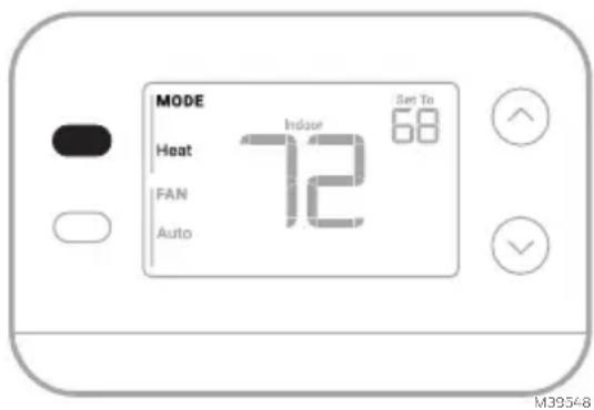
System Operation Settings
- Press the MODE button to cycle to the next available System mode
- Cycle through the modes until the desired System mode is displayed Available System modes vary with system settings.
System modes:
• AUTO
- HEAT
• COOL
• OFF
text_image
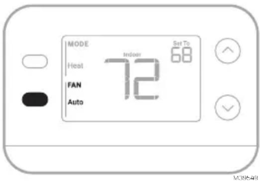
MODE Heat Indose Set To FAN 72 68 Auto M39548Fan Operation Settings
- Press the FAN button to cycle to the next available Fan mode
- Cycle through the modes until the desired Fan mode is displayed Available Fan modes vary with system settings.
Fan modes:
- AUTO : Fan runs only when the heating or cooling system is on
• ON: Fan is always on - CIRC: Fan runs about 33% of the time to circulate air.
text_image
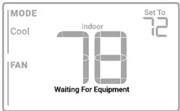
MODE Heat FAN Auto Indoor Set To 68 M39548Built-in Compressor Protection
Damage can occur if your system's compressor is restarted too soon after shutdown. This feature forces the compressor to wait for a few minutes before restarting. During the wait time, the display will show the message Waiting For Equipment under the room temperature reading.
When the safe wait time has elapsed, the message disappears, and the thermostat will show “Heat on” or “Cool on”.
text_image
MODE Cool FAN Indoor 78 Waiting For Equipment Set To 72M39564
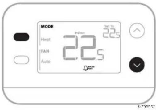
Alerts and Reminders

text_image
MODE Host FAN Auto 72 Stop 72 OK| Alert Number Alert Meaning | |
| 405 | Low batteries (see Battery Replacement section) |
| 407 | Critically low batteries (see Battery Replacement section) |
| 170 Thermostat memory failure | |
| 173 Internal Sensor Error. Issue with the built-in temperature sensor. | |
| 181 | Replace filter (Reset this timer after replacing furnace filter by pressing and holding the upper left and lower right buttons for 5 seconds.) |
When an alert is active, an icon will appear in the lower part of the display. Pressing the lower left button, then the upper right button will show the alert # over the temperature reading.
When the filter Reminder is active the 🔔 icon appears as well as Replace Filter.
Troubleshooting
| Display is blank | Make sure fresh AA alkaline batteries are correctly installed (see Step 7 of the section Installing the Thermostat) |
| Heating or cooling does not run | When running heat, display will show HEAT ON in lower right of displayWhen running cool, display will show COOL ON in lower right of displayIf display shows WAITING FOR EQUIPMENT under temperature reading, it is in compressor delay mode to protect the system. Wait 5 minutes to see if the thermostat makes a Heat or Cool callIf display does not indicate a call for Heat or Cool or WAITING FOR EQUIPMENT, verify the mode setting, temperature setpoint and room temperatureIf the Up or Down arrow is pressedUpper left of display shows mode settingUpper right shows setpointCenter of display shows room temperatureIf the issue persistsCheck circuit breaker and reset if necessaryMake sure power switch at heating & cooling system is onMake sure furnace door is closed securely |
| Heat runs with Cooling | Verify there is not a wire attached to W for heat pump systems. See Wiring sectionFor heat pump applications the reversing valve is energized in Heat on some heat pumps and Cool for other heat pumps. Verify that ISU 2060 is set correctlyVerify that no wires are shorted. Look for exposed sections of wire at the UWP |
| Heat runs with no call for heat or cooling | Verify display does not indicate HEAT ON or COOL ONVerify there is not a wire attached to W for heat pump systems. See Wiring section.Verify that no wires are shorted. Look for exposed sections of wire at the UWP |
| Cannot change setpoint to desired setting | Verify the mode setting (Heat, Cool or Auto in upper left of display)The setting ranges for these modes are:Heat: 32 °F to 90 °F (0 °C to 32.0 °CCool: 50 °F to 99 °F (10.0 °C to 37.0 °C) |
| WAITING FOR EQUIPMENT shown in display under room temperature | The compressor protection feature is engaged. Wait a few minutes for the system to safely restart to avoid damaging the compressor. |
Notes
Notes
Notes
Regulatory Information
FCC REGULATIONS
47 CFR § 15.19 (a)(3)
This device complies with part 15 of the FCC Rules.
Operation is subject to the following two conditions:
1 This device may not cause harmful interference, and
2 This device must accept any interference received, including interference that may cause undesired operation.
47 CFR § 15.21 (USA only)
Changes or modifications not expressly approved by the party responsible for compliance could void the user's authority to operate the equipment.
47 CFR § 15.105 (b)
See https://customer.resideo.com/en-US/support/residential/codes-and-standards/FCC15105/Pages/default.aspx for additional FCC information for this product.
IC REGULATIONS
RSS-GEN
This device contains licence-exempt transmitter(s)/receiver(s) that comply with Innovation, Science and Economic Development Canada's licence-exempt RSS(s). Operation is subject to the following two conditions:
1 This device may not cause interference.
2 This device must accept any interference, including interference that may cause undesired operation of the device.
1-year Limited Warranty
For Warranty information go to Honeywellhome.com/support

CAUTION: ELECTRICAL HAZARD
Can cause electrical shock or equipment damage. Disconnect power before beginning installation.

CAUTION: EQUIPMENT DAMAGE HAZARD
Compressor protection is bypassed during testing. To prevent equipment damage, avoid cycling the compressor quickly.

CAUTION: MERCURY NOTICE
If this product is replacing a control that contains mercury in a sealed tube, do not place the old control in the trash. Contact your local waste management authority for instructions regarding recycling and proper disposal.

CAUTION: ELECTRONIC WASTE NOTICE
The product should not be disposed of with other household waste. Check for the nearest authorized collection centers or authorized recyclers. The correct disposal of end-of-life equipment will help prevent negative consequences for the environment and human health.
FCC statement available at: https://customer.resideo.com/en-US/support/residential/codes-and-standards/FCC15105/Pages/default.aspx
Customer Assistance
For assistance with this product, please visit honeywellhome.com
Or call Resideo Customer Care toll-free at 1-800-633-3991

resideo
www.resideo.com
Resideo Technologies Inc.
Scottsdale, AZ 85254
33-00687EFS-03 L.Y. Rev. 11-24
text_image
Black and white barcode image with vertical lines and dots, no readable text or symbols33-00687EFS-03
Honeywell Home

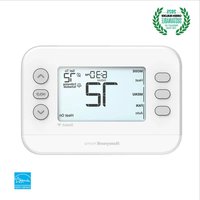
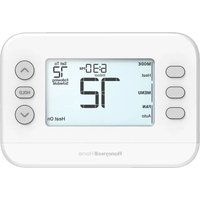
Thermostat non programmable X1N RTH11B/RTHC11B
text_image
MODE Heat To 23s FAN 22.0 Auto Heat On MF39547natural_image
Line drawing of a handheld electric drill (no text or symbols)
Pinces à bec effilé
Perceuse et mèche
LISEZ ET CONSERVEZ CES INSTRUCTIONS Installation et câblage
text_image
Illustration showing a hand inserting a credit card into a banknote with arrows indicating the card's usage.natural_image
Illustration of a hand holding a smartphone displaying a grid-based interface with icons, next to a device with buttons (no text or symbols visible)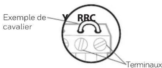
text_image
Exemple de cavalier RRC Terminauxtext_image
□ R □ RH □ Rcnatural_image
Hand holding a device with a grid and buttons, showing a hand pressing down (no text or symbols visible)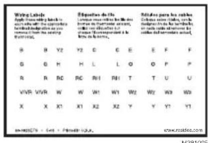
text_image
Wing Labels Apply the following back to see the right side of the appropriate founded designations as you removed from the setting FOMING. Equations de l'les L'ouvrant une reûche le M de hous de la courative formation, deux un d'ouvrant et l'ouvrant de la courative formation. R B Y2 Y2 C E E F F G G H H L L O O P P R R RC RC RH1 RH1 T T U U VVR VVR W W W1 W1 W2 W2 W3 W3 X X X1 X1 X2 X2 Y Y Y1 Y1 www.roidice.com M281005text_image
1/4" to 3/8" M39442A
text_image
90° M37224natural_image
Illustration of hands using a tool to adjust cable or wire on a plug (no text or symbols visible)text_image
S 0 S 0 Y 0 Y2 0 G 0 C 0 U 0 U LIA O/B AUDnatural_image
Simple diagram of a battery pack with two side batteries labeled 'AA' (no text or symbols on the battery itself)M39489
natural_image
Line drawing of a hand holding a smartphone with arrows indicating the process (no text or symbols present)natural_image
Illustration of a hand holding a smartphone with arrows pointing to the screen (no text or symbols)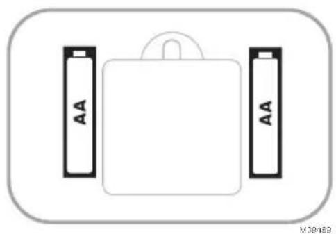
natural_image
Simple diagram of a battery pack with two AA batteries on top, no text or symbols presenttext_image
ISU V305/M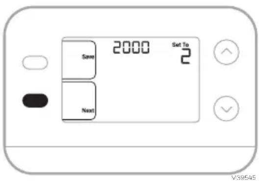
text_image
2000 Set To Save 2 Next V39545text_image
MODE Indoor Set To 22.0 Heat 22.5 IFAN Auto MF39548text_image
MODE Heat FAN Auto 22.5 Set To 22.0 M-38549text_image
MODE Cool Indoor Set To 22.5 FAN 25.5 Waiting For Equipment MI-39564Alertes et rappels
text_image
MODE Heat Indusin Set To 22.5 IFAN 22.5 Auto MF3955247 CFR § 15.19 (a)(3)
47 CFR § 15.21 (USA uniquement)
https://customer.resideo.com/en-US/support/residential/codes-and-standards/
FCC15105/Pages/default.aspx
Resideo Technologies Inc.
Scottsdale, AZ 85254
33-00687EFS-03 L.Y. Rev. 11-24
text_image
Black and white barcode image with vertical lines and a small number '1' at the bottom right.33-00687EFS-03
Honeywell Home

Termostato no programable X1N
RTH11B/RTHC11B
text_image
MODE Heat To 23s FAN 22.0 Auto Heat OnMS39547
natural_image
Line drawing of a handheld electric drill (no text or symbols)Taladro y broca
LEA Y GUARDE ESTAS INSTRUCCIONES
natural_image
Illustration of a hand inserting a credit card into a banknote (no text or symbols visible)natural_image
Illustration of a hand holding a smartphone displaying a connector, with a close-up of its connector being inserted (no text or symbols visible)text_image
□ R □ RH □ Rctext_image
Diagram showing hand holding a device with labeled buttons and arrows indicating action or sequence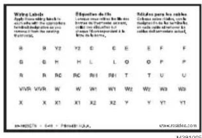
text_image
Wiring Labels Apply the following key to in which the object is founded into the series from the second series and from the second series. B Y2 Y2 C D E F F G H H L L O P P R R RC RC RH RH T T U U VWR WWR W W1 W1 W2 W2 W3 W3 X X X1 X1 X2 X2 Y Y Y1 M-00275 - 641 - Private: USA. Exposition de l'ls Lorraine ouvrouche le Mède hors de la fréderme sauture, malle une d'échette et l'assurant de la fréderme sauture. Rédules par les rèdes Clômes sain châne, cale maigrés de la trérature en lae d'échette et lauf de la fréderme sauture. M-00275 - 641 - Private: USA. www.routdec.com M-2910GEtext_image
1/4" to 3/8" M39442A
text_image
90° M37224natural_image
Illustration of hands using a tool to adjust cable or wire on a plug (no text or symbols visible)text_image
oY1oM oF oC1oXoB 3 4 S S Y Y2 G C U U L/A A O/B AUX W2 E W K R Rc oW1oH oRHo4oV 1 2 1 2 MS39606Bomba de calor
text_image
S 0 S 0 Y 0 Y2 0 G 0 C 0 U 0 U L/A O/B A/Dnatural_image
Simple diagram of a battery pack with two side batteries labeled 'AA' (no text or symbols on the battery itself)M39489
natural_image
Line drawing of a hand holding a smartphone with arrows indicating the process (no text or symbols present)natural_image
Line drawing of a hand holding a smartphone with arrows pointing to the screen (no text or symbols)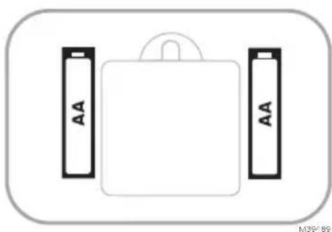
natural_image
Simple diagram of a battery pack with two side batteries labeled 'AA' (no text or symbols beyond labels)text_image
ISU V305/M
text_image
2000 Set To Save 2 Next V39545text_image
MODE Heat FAN Auto Indoor Set To 22.0 22.5 MS39548text_image
MODE Heat FAN Auto Indoor Set To 22.0 22.5 MS39549text_image
MODE Cool FAN Indoor Set To 22.5 25.5 Waiting For EquipmentMS39564
47 CFR § 15.19 (a)(3)
https://customer.resideo.com/en-US/support/residential/codes-and-standards/
FCC15105/Pages/default.aspx
Resideo Technologies Inc.
Scottsdale, AZ 85254
33-00687EFS-03 L.Y. Rev. 11-24
text_image
Black and white barcode image with vertical lines above and below the bars33-00687EFS-03