
Hot Spot Crystal Flow - Pan Klarstein - Free user manual and instructions
Find the device manual for free Hot Spot Crystal Flow Klarstein in PDF.

| Product type | Wall-mounted electric heater |
| Brand | Klarstein |
| Model | Hot Spot Crystal Flow |
| Power supply | 220-240 V ~ 50 Hz |
| Maximum power | 2000 W (1800 W + 200 W) |
| Power levels | 3: high (1800 W), low (1100 W), panel (200 W) |
| Heating type | PTC (Positive Temperature Coefficient) |
| Protection | IPX4 (splash-proof) |
| Installation | Wall-mounted, minimum height 600 mm from floor |
| Material | Tempered glass panel, metal body |
| Thermostat | Electronic with weekly and daily programming |
| Special functions | Presence detector, open window detection, frost protection, child lock, 24-hour timer |
| Towel holder | Included (two sizes) |
| Maintenance | Removable filters, vacuum cleaning, damp cloth |
| Display | LED screen with touch keys |
| Included accessories | Wall bracket, screws, wall plugs, drilling template, towel holder |
| Safety | Automatic shut-off in case of overheating, presence detection |
| Repairability | No user-serviceable parts, intervention by a qualified electrician required |
| Recycling | Do not dispose with household waste, take to WEEE collection point |
| Manufacturer | Chal-Tec GmbH, Wallstraße 16, 10179 Berlin, Germany |
Frequently Asked Questions - Hot Spot Crystal Flow Klarstein
User questions about Hot Spot Crystal Flow Klarstein
0 question about this device. Answer the ones you know or ask your own.
Ask a new question about this device
Download the instructions for your Pan in PDF format for free! Find your manual Hot Spot Crystal Flow - Klarstein and take your electronic device back in hand. On this page are published all the documents necessary for the use of your device. Hot Spot Crystal Flow by Klarstein.
USER MANUAL Hot Spot Crystal Flow Klarstein
HOT SPOT CRYSTAL FLOW
Badheizer mit Handtuchhalterung Bathroom Heater with Towel Rack Radiateur de salle de bain avec porte-serviette Toallero calefactor para baño Stufa da bagno con scaldasalviette Badkamerverwarming met handdo- ekhouder
10035035

COMFORTING OMFORTING FORTINGCOM TINGCOMFO COMFORTING OMFORTING FORTINGCOM TINGCOMFO
KLARSTEIN
www.klarstein.com
Note: The device is not suitable for use as a primary heat source.
INHALT
natural_image
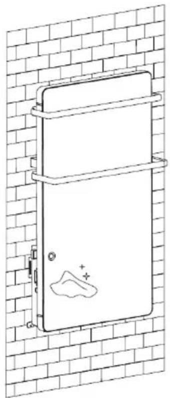
Line drawing of a double door mounted on a brick wall, with a small cloud icon and plus signs (no text or symbols)GERÄTEÜBERSICHT
natural_image
Technical diagram of a door mounted on a brick wall, with screwdriver inserted and directional arrows indicating movement (no text or symbols)Wartung
Member of Berlin Brands Group
Handwerkerstr. 11
15366 Dahlwitz-Hoppegarten
Deutschland
natural_image
Symbol of a trash bin crossed with a diagonal line, no text or labels presentBerlin Brands Group UK Limited
PO Box 42
272 Kensington High Street
London, W8 6ND
United Kingdom
Congratulations on purchasing this equipment. Please read this manual carefully and take care of the following hints to avoid damages. Any failure caused by ignoring the items and cautions mentioned in the instruction manual are not covered by our warranty and any liability. Scan the QR code to get access to the latest user manual and other information about the product.

CONTENTS
Safety Instructions 28
Installation 32
Appliance Overview 37
Operation 38
Cleaning and Maintenance 43
Disposal Considerations 44
Manufacturer & Importer (UK) 44
Technical Parameters 45
TECHNICAL DATA
| Item number 10035035 | |
| Power supply 220-240 V~ 50 Hz | |
| Power consumption 2000 W | |
| IP rating IPX4 | |
SAFETY INSTRUCTIONS
- Read all instructions before using this unit.
- Do not leave this unit unattended when in use.
- This heater will get hot when in use. Do not touch hot surfaces.
CAUTION
Risk of burns! Some parts of this product can become very hot and cause burns. Particular attention has to be given when children and vulnerable people are present.
- The heater must not be located immediately below a socket-outlet.
- Do not move the unit when in use. Wait until the heater is completely cool before moving and check that it has been unplugged from the power supply.
- Position the unit at least 1 m away from highly combustible materials such as furniture, trees, leaves, dry grass and bushes.
- The heater must not face with the heating element pointing upwards towards a ceiling. The heater element must be facing the area it is to heat.
Note: In order to avoid overheating do not cover the heater. It is not for drying clothes.
- Keep children and pets at a safe distance from the unit.
- This heater can be used by children aged from 8 years and above and persons with reduced physical, sensory or mental capabilities or lack of experience and knowledge if they have been given supervision or instruction concerning use of the heater in a safe way and understand the hazards involved. Children shall not play with the appliance. Cleaning and user maintenance shall not be made by children without supervision. Children of less than 3 years should be kept away unless continuously supervised.
- Children aged from 3 years and less than 8 years shall only switch on/off the heater provided that it has been placed or installed in its intended normal operating position and they have been given supervision or instruction concerning use of the heater in a safe way and understand the hazards involved. Children aged from 3 years and less than 8 years shall not plug in, regulate and clean the heater or perform user maintenance.
- Do not operate the heater if any signs of damage or malfunction manifest themselves.
- Do not attempt to repair or adjust any electrical or mechanical functions on this unit. The unit does not contain any user serviceable parts. Only a qualified electrician should perform servicing or repairs.
- If the power cable is damaged, it must be replaced by the manufacturer, its service agent or similarly qualified persons in order to avoid a hazard. Do not replace or attempt to replace the element in this product.
- Do not use this heater in the immediate surroundings of a bath, shower or swimming pool.
- Do not touch the plug with wet or damp hands.
- Do not run the power cable under carpeting. Do not cover the power cable with rugs, runner, or similar coverings. Arrange the power cable away from foot traffic and where it will not be tripped over.
- Do not wind the power cable around the unit.
- Do not insert or allow foreign objects to enter any ventilation or opening on the heater, as this may result in electric shock, fire, or damage to the heater.
- To prevent a possible fire, do not block the air vents.
- A heater has hot and arcing or sparking parts inside. Do not use in areas where petrol, paint, explosive and/or flammable liquids are used or stored. Keep unit away from heated surfaces and open flames.
- Where possible, avoid the use of an extension cable as this may overheat and cause a fire. However, if you have to use an extension cable, ensure it is suitable for the purpose, has been tested for outdoor use and preferably has an RCD device fitted or attached.
- Always unplug the unit and ensure the unit is completely cold before moving, cleaning or storing.
- This heater is intended for domestic use only and should not be used commercially for contract purposes. Any alternative use, not recommended by the manufacturer, may result in fire, electric shock, or injury to persons.
- Means for disconnection having a contact separation in all poles must be incorporated in the fixed wiring in accordance with the wiring rules.
- The use of attachments on the heater is not recommended.
- Do not use this heater with a programmer, timer, separate remote control system or any other device that switches the heater on automatically, since a fire risk exists if the heater is covered or positioned incorrectly.
INSTALLATION
Installation Notes

WARNING
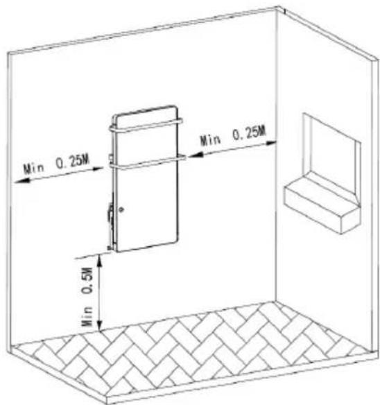
Risk of injury! In order to avoid a hazard for very young children, this heater should be installed so that the lowest heated rail is at least 600 mm above the floor.
• This heater must be installed by a qualified person, that is, a qualified electrician.
- Before installation and during installation, ensure that the heater is always disconnected from the power supply and is in a cool state.
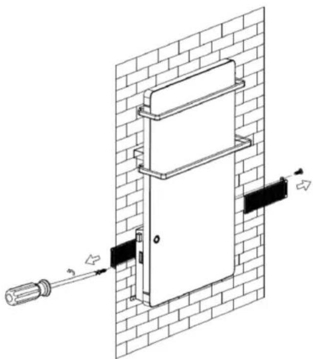
Fixation of the heater on wall
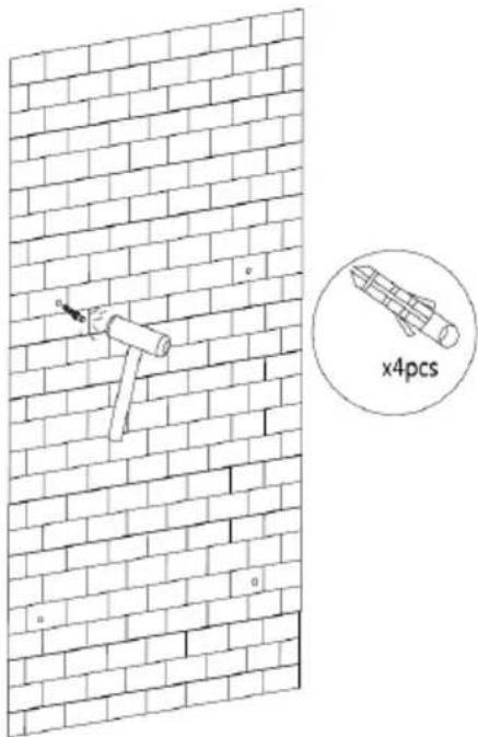
- Choose a wall where has enough space and is suitable to installing the appliance.
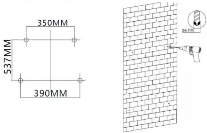
- Use the enclosed template to mark the holes to be drilled on the wall. Then drill 4 holes ∅6 each into the wall.
- Please insert one peg per hole into the wall and push them in with a hammer until the pegs no longer stick out from the wall.
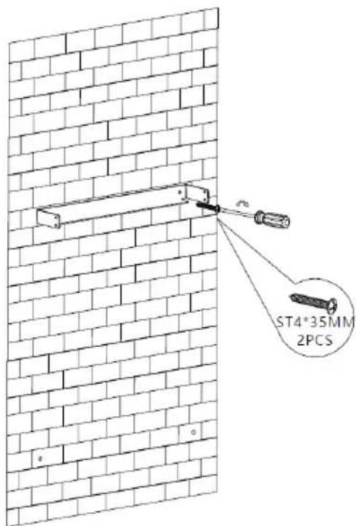
- Fix the wall bracket to the two upper holes using two ST4X35 screws.
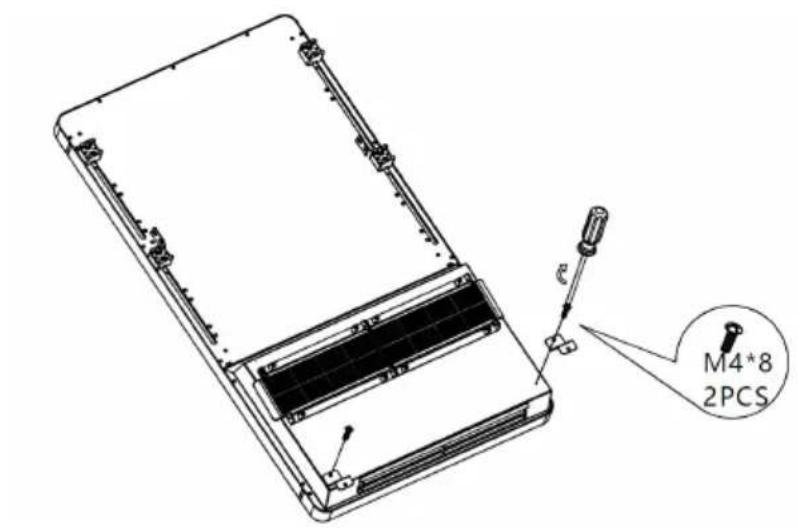
- Fasten the two Z-brackets to the back of the heater with two M4X8 screws.
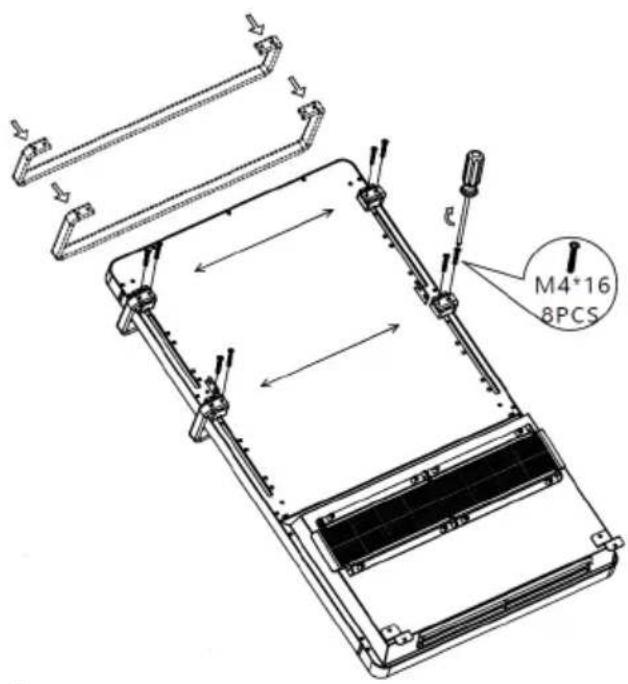
- Insert the smaller towel rack into the provided brackets and screw it tight with four M4X16 screws. Follow the same way to fix the larger towel rack with four M4X16 screws. (Skip this step when towel racks are not needed.)
- Two persons are required for the following assembly steps Place the appliance on the wall bracket and fasten it on the left and right side with two M4X10 screws to the wall bracket.
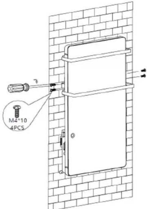
- Fix the Z-brackets to the wall with two ST4X35 screws. The screws should fit into the two previously drilled lower holes.
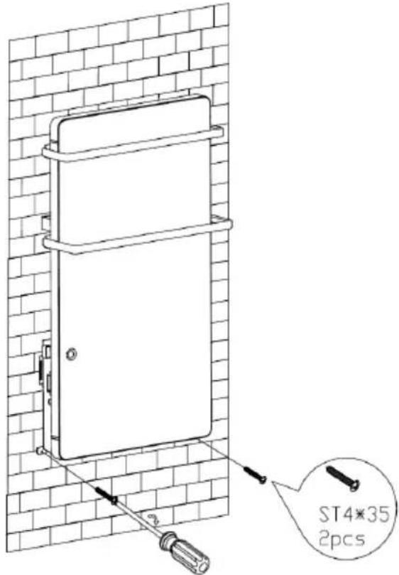
- Wipe the surface of the appliance with a soft cloth. The appliance is ready for operation.
natural_image
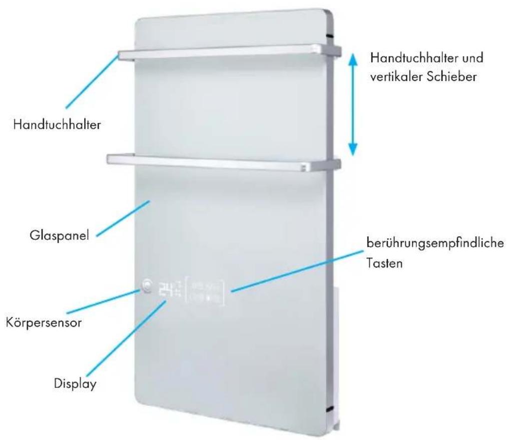
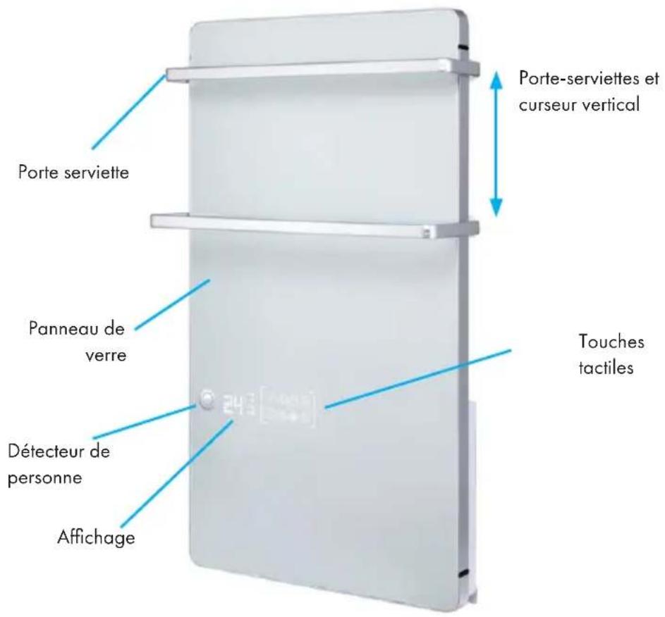
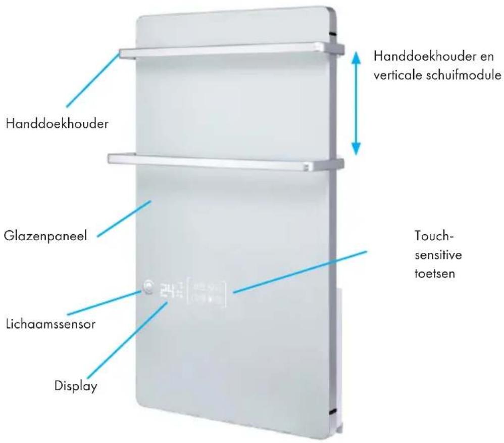
Line drawing of a double door mounted on a brick wall, with a small mountain icon and plus signs (no text or symbols)APPLIANCE OVERVIEW
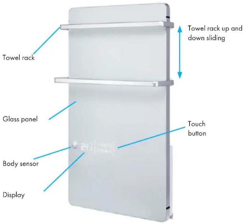
OPERATION
Control panel
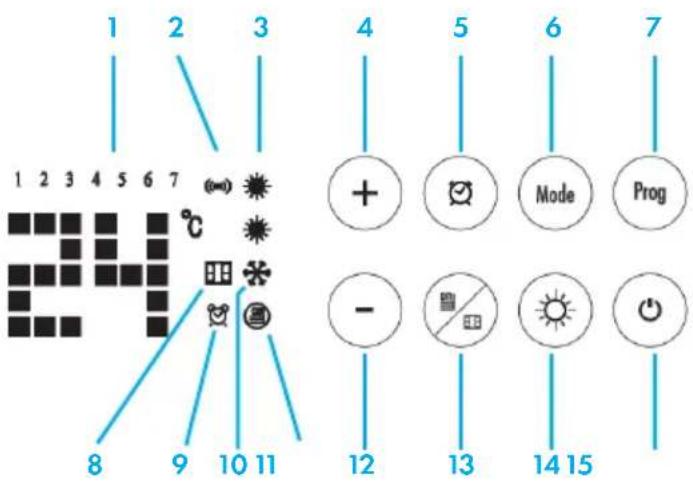
- Week day
- Body sensor
- PTC power setting
- Value Increase
- 24H Timer
- Mode Setting
- Program setting
- Window open detection
- Week timer
- Anti-frost
- Panel heating
- Value Decrease
- Panel Heating/Window open detection
- PTC Heating Power setting
- ON/ STANDBY
Plug in supply of 220-240V\~50Hz. Push the ON/OFF (0/I) button located at the left side of the heater to switch it on. Buzzer will have a short "D" sound. Display and button will light up for 10s.
Touch once to turn on heating. Button light will go out in 10s when no operation is conducted. Touch any button could reactivate the button light.
Touch once again to turn off heating. The appliance stays in standby mode.
Note: Motor will continue working for extra 15s to drive away the residue heat inside unit before turning off.
To switch the appliance off, push ON/OFF (0/1) button again and disconnect the plug.
Set local day and time
At the first time usage, icon will keep flashing to remind user to set local day and time before further operation.
Long touch button for 3 seconds to activate timer setting, figure 1 of '1 2 3 4 5 6 7' will flash, touch '+' or '-' to select the day, the selected figure will flash accordingly. Touch to confirm the day setting. Then come to hour-setting, '88' flashes, touch + or - to select the hour among 0-23, touch to confirm hour setting. Then come to minute-setting, '88' flashes, touch + or - to select the minute among 0-59. Touch to confirm minute setting.
Note: program will automatically return to initial display in 10s when no operation is conducted during setting.
Power Setting
| Power Icon Display Function | |||
| PTC heating high power 1800 W |  | Room heating | |
| PTC heating low power 1100 W Room heating |  | ||
| Panel Heating 200 W Towel heating |  | ||
| Full power 1800 W +200 W= 2000 W |   | Room heating+ towel heating | |
- PTC heating (1800W): Touch ⓞ button to turn on the appliance. Both icons light up, PTC heating is working at high power 1800W. Touch once to switch it low power 1100W, only one icon lights up.
- Panel Heating (200W): Touch ①ice to start panel heating.
- Full power heating (2000W): When panel heating works, touch ⚙ to switch PTC heating at high power 1800W. Then total power is 2000W.
Note: at this stage, touch will switch PTC heating from high power – low power – no power (1800W- 1100W- 0W)
WARNING
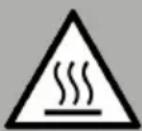
Risk of burns! The glass surface and air outlet bottom will become very hot. Be careful and avoid touching it.
Temperature Setting
After power is set, touch + or - to set temperature among 5-40 °C.
The display screen will change accordingly. Once temperature is set, the setting will be confirmed in 5s automatically.
When ambient temperature reaches the set temperature, appliance will stop heating.
When ambient temperature drops 1 °C lower than the setting, appliance will resume heating to keep the ambient temperature at set level.
Note: Set temperature must be higher than ambient temperature. Or appliance will not start heating.
Mode Setting of Week Timer - Auto Start
In standby mode, touch button to switch working mode among P1-P2-P3-P4-P5-UP, then touch to confirm setting.
P1, P2, P3, P4, P5 modes are default program for quick setting
• P1: all day comfort mode
• P2: mode for general family
• P3: mode for working office
• P4: mode for commercial plaza
• P5: mode for family on travel or trip
| Week day mode | Working mode | |||||||
| Anti-frost Comfort Anti-frost Comfort Anti-frost Comfort Anti-frost | ||||||||
| 1-7 P1 | 00:00-24:00 | |||||||
| 1-5 | P2 | 00:00-06:30 | 06:30-08:30 | 08:30-17:00 | 17:00-22:30 | 22:30-24:00 | ||
| 6-7 | 00:00-07:30 | 07:30-10:00 | 10:00-12:00 | 12:00-14:00 | 14:00-17:00 | 17:00-22:30 | 22:30-24:00 | |
| 1-5 | P3 | 00:00-06:00 | 06:00-17:00 | 17:00-24:00 | ||||
| 6-7 | 00:00-24:00 | |||||||
| 1-7 P4 | 00:00-06:00 | 06:00-22:00 | 22:00-24:00 | |||||
| 1-7 P5 | 00:00-24:00 | |||||||
UP mode is week timer setting of comfort / anti-frost set by end-user.
Once UP mode setting is activated, figure 1 (Monday) of '1 2 3 4 5 6 7' and begin flashing. (rights up.
Example 1 - set one or three (at most) time-range at comfortable level, then follow steps as below,
Touch + or -. The LED displays 1 (1st working-hour) & flashes. Touch + or - to select the start time of 1st working-hour among 0-23. Once selected, touch to confirm it. Touch + to set end time. Then touch to confirm 1st setting.
Note: The end time must be at least 1 hour more than start time.
The LED turns to display 2 (2nd working-hour), repeat the same steps of 1st working hour to set 2 more time-range at most upon your need.
After one day setting is finished, figure 2 (Tuesday) of '1 2 3 4 5 6 7' begin flashing, repeat the same steps above to set working hour of each day among.
Example 2 - Touch directly instead of + or -, to leave that day at anti-frost function.
Note: each step must be operated within 2 min, or it will exist setting and screen will recover to initial display.
Anti-frost: appliance keep room temperature at default 5 °C to prevent frost.
Comfort: comfortable level achieved by setting power and temperature upon need.
(Reference to step 2&3)
Body Sensor
Once PI-P2-P3-P4-UP mode is set, body detector will be activated at the same time. The icon (W) light up.
When the pre-set timing of week timer comes, appliance will start heating. At the first 15 minutes, if no absence is detected in the room, appliance will stop heating and stay at standby mode. Once body sensor finds any come-in person, the appliance will start heating again.
Note: Body detector only take effects on comfort mode. No function in anti-frost mode.
24 Hour Timer – Auto Off
In P1 mode, touch twice quickly to activate 24 hour timer setting, icons & flash. Touch + or - to set timer among 0 to 24. Leave the setting for 5s, stops flashing, stops flashing and will keep lighting up, timer setting is confirmed. Screen will show ambient temperature and counting-down hour in turn.
Touch again could cancel the setting. Screen will turn to show room temperature.
Child Lock Function
In standby mode, long touch + and - at the same time for 3 seconds to activate child lock function, screen will show '[...].' after setting and will recover to initial display in 5 seconds. Other function is invalid once child lock function works. Once button is touch, screen will flash '[...].' to remind you child lock function is working and recover to initial display in 5 seconds.
Long touch + and - at the same time for 3 seconds again could cancel child lock function.
Window Open Detection Function
In any working mode (in spite of anti-frost), long touch for 3 seconds to activate window open detection icon flashes on the screen.
Long touch for 3 seconds again could cancel the setting, the window open detection icon disappears.
In window open detection mode, room temperature is found to drop 5^ C in 10 minutes when appliance is heating. Appliance will consider the window may be open and start detection. In the next 30 minutes, if room temperature is found to be the same or lower
than before, appliance will consider the window is open and stop heating. At the same time, the icon stops flashing and keep lighting up to remind user to close the window. When the window is closed, touch 🔔 to recover normal operation, flashes again.
Recovery of Factory Setting
Touch + and - at the same time twice quickly. The appliance will recover to initial factory setting.
CLEANING AND MAINTENANCE
The filter will become very dirty after day after day usage. Please clean the filter after around 150 hour usage.
Steps to remove and assemble filter
Use screw driver to unscrew 2 screws ST3X10 from filter, then remove the left and right filters. Re-assemble the filter according to the reference line (see drawing below). Push the filter to the end until it cannot move anymore.
natural_image
Technical line drawing of a door mounted on a brick wall, with screwdriver inserted and directional arrows indicating movement (no text or symbols)Maintenance
-
Always disconnect the heater and let it cool down completely before carrying out any maintenance.
-
Use a vacuum cleaner to remove dust on inlet and outlet surfaces.
-
Clean the outside of the unit with a damp cloth and then dry it with a dry cloth. Never immerse the unit in water, nor let water drip into the unit.
Storage
- Always disconnect the appliance, let it completely cool and clean it before storing.
- If you do not use the device for a long period, put back the unit and the instruction manual back into the original carton and store in a dry and ventilated place.
- Do not place any heavy items on top of carton during storage as this may damage the appliance.
DISPOSAL CONSIDERATIONS
natural_image
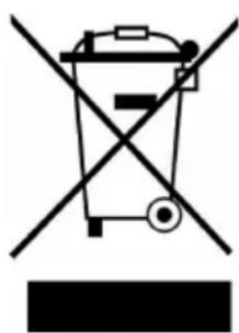
Symbol of a trash bin crossed with a diagonal line, no text or labels presentIf there is a legal regulation for the disposal of electrical and electronic devices in your country, this symbol on the product or on the packaging indicates that this product must not be disposed of with household waste. Instead, it must be taken to a collection point for the recycling of electrical and electronic equipment. By disposing of it in accordance with the rules, you are protecting the environment and the health of your fellow human beings from negative consequences. For information about the recycling and disposal of this product, please contact your local authority or your household waste disposal service.
MANUFACTURER & IMPORTER (UK)
Manufacturer:
Chal-Tec GmbH, Wallstrasse 16, 10179 Berlin, Germany.
Importer for Great Britain:
Berlin Brands Group UK Limited
PO Box 42
272 Kensington High Street
London, W8 6ND
United Kingdom
TECHNICAL PARAMETERS
| Model identifier(s): 10035035 | ||||||
| Item Symbol Value Unit Item Unit | ||||||
| Heat output Type of heat input, for electric stor- | age local space heaters only | |||||
| Nominal heat output | P_nom | 2.0 | kW | manual heat charge control, with integrated thermostat | no | |
| Minimum heat out-put (indicative) | P_min | 1.1 | kW | manual heat charge control with room and/or outdoor temperature feedback | no | |
| Maximum continu-ous heat output | P_max | 2.0 | kW | electronic heat charge control with room and/or outdoor temperature feedback | no | |
| Auxiliary electricity consumption | fan assisted heat output | no | ||||
| At nominal heat output (fan motor) | el_max | 0 | kW | Type of heat output/room temperature control | ||
| At minimum heat output (fan motor) | el_min | 0 | kW | single stage heat output and no room temperature control | no | |
| In standby mode | elsB | 0 | kW | Two or more manual stages, no room temperature control | no | |
| with mechanic thermostat room temperature control | no | |||||
| with electronic room temperature control | no | |||||
| electronic room temperature con-trol plus day timer | no | |||||
| electronic room temperature con-trol plus week timer | yes | |||||
| Other control options (multiple selections possible) | ||||||
| room temperature control, with presence detection | yes | |||||
| room temperature control, with open window detection | yes | |||||
| with distance control option | no | |||||
| with adaptive start control no | ||||||
| with working time limitation | yes | |||||
| with black bulb sensor | no | |||||
| Contact details | Chal-Tec GmbH, Wallstraße 16, 10179, Berlin, Germany | |||||
Chère cliente, cher client,
SOMMAIRE
natural_image
Line drawing of a double door mounted on a brick wall, with a small mountain icon and plus signs (no text or symbols)APERÇU DE L'APPAREIL
natural_image
Technical diagram of a door mounted on a brick wall, with screwdriver inserted and arrows indicating assembly (no text or symbols)Maintenance
natural_image
Symbol of a trash bin crossed with a diagonal line, no text or labels presentBerlin Brands Group UK Limited
PO Box 42
272 Kensington High Street
London, W8 6ND
United Kingdom
FICHE DE DONNÉES PRODUIT
ÍNDICE
natural_image
Line drawing of a double door mounted on a brick wall, with a small mountain icon and plus signs (no text or symbols)natural_image
Technical line drawing of a door mounted on a brick wall, with screwdriver inserted and arrows indicating force or movement (no text or symbols)Mantenimiento
natural_image
Symbol of a trash bin crossed with a diagonal line, no text or numbers presentBerlin Brands Group UK Limited
PO Box 42
272 Kensington High Street
London, W8 6ND
United Kingdom
HOJA DE DATOS DEL PRODUCTO
INDICE
natural_image
Line drawing of a double door mounted on a brick wall, with a small mountain icon and plus signs (no text or symbols)natural_image
Technical diagram of a door mounted on a brick wall, with screwdriver inserted and arrows indicating assembly (no text or symbols)Manutenzione
natural_image
Symbol of a trash bin crossed with a diagonal line and a horizontal bar below (no text or labels)PRODUTTORE E IMPORTATORE (UK)
Produttore:
Chal-Tec GmbH, Wallstraße 16, 10179 Berlino, Germania.
Berlin Brands Group UK Limited
PO Box 42
272 Kensington High Street
London, W8 6ND
United Kingdom
SCHEDA INFORMATIVA DEL PRODOTTO
INHOUD
natural_image
Line drawing of a double door mounted on a brick wall, with a small snow icon and plus signs (no text or symbols)OVERZICHT APPARAAT
natural_image
Technical diagram of a door mounted on a brick wall, with screwdriver inserted and directional arrows indicating movement (no text or symbols)Onderhoud
INSTRUCTIES VOOR AFVOER

natural_image
Symbol of a trash bin crossed with a diagonal line, no text or labels presentBerlin Brands Group UK Limited
PO Box 42
272 Kensington High Street
London, W8 6ND
United Kingdom


- HOT SPOT CRYSTAL FLOW
- INHALT
- GERÄTEÜBERSICHT
- Wartung
- Member of Berlin Brands Group
- Handwerkerstr. 11
- Dahlwitz-Hoppegarten
- Deutschland
- CONTENTS
- SAFETY INSTRUCTIONS
- CAUTION
- INSTALLATION
- Installation Notes
- WARNING
- Fixation of the heater on wall
- APPLIANCE OVERVIEW
- OPERATION
- Control panel
- Set local day and time
- Temperature Setting
- Mode Setting of Week Timer - Auto Start
- Body Sensor
- Hour Timer – Auto Off
- Child Lock Function
- Window Open Detection Function
- Recovery of Factory Setting
- CLEANING AND MAINTENANCE
- Steps to remove and assemble filter
- Maintenance
- Storage
- DISPOSAL CONSIDERATIONS
- MANUFACTURER & IMPORTER (UK)
- Manufacturer:
- Importer for Great Britain:
- TECHNICAL PARAMETERS
- Chère cliente, cher client,
- SOMMAIRE
- APERÇU DE L'APPAREIL
- ÍNDICE
- Mantenimiento
- HOJA DE DATOS DEL PRODUCTO
- INDICE
- Manutenzione
- PRODUTTORE E IMPORTATORE (UK)
- Produttore:
- INHOUD
- OVERZICHT APPARAAT
- Onderhoud
- INSTRUCTIES VOOR AFVOER
Brand : Klarstein
Model : Hot Spot Crystal Flow
Category : Pan