10FT-3D-7K-J - Sliding door hardware Vevor - Free user manual and instructions
Find the device manual for free 10FT-3D-7K-J Vevor in PDF.

| Product Type | Sliding Barn Door Hardware Kit |
| Model | 10FT-3D-7K-J |
| Brand | Vevor |
| Track Length | 10 ft (3000 mm) |
| Max Door Width | 60 inches |
| Door Thickness Compatibility | 1-3/8" to 1-3/4" |
| Color | Black |
| Hanger Type | J-Mold |
| Number of Track Sections | 3 |
| Number of Mounting Holes | 7 |
| Included Components | Rail kit (3 pcs), hangers (2), anti-jump blocks (2), door stoppers (2), T-shape floor guide (1), wall spacers, bolts, screws, hex key |
| Material | Steel (track), plastic (expansion bolts) |
| Application | Single sliding barn door (interior) |
| Installation Requirement | Header board recommended if wall studs not 16" on center or for non-concrete walls |
| Safety Features | Anti-jump blocks, door stoppers |
| Weight Capacity | Not specified (typical for door weight up to ~150 lbs) |
| Maintenance | Clean with damp cloth; lubricate track periodically (not included) |
| Certifications | CE, UKCA (via importer) |
| Warranty | E-warranty certificate available at www.vevor.com/support |
| Country of Origin | China |
Frequently Asked Questions - 10FT-3D-7K-J Vevor
User questions about 10FT-3D-7K-J Vevor
0 question about this device. Answer the ones you know or ask your own.
Ask a new question about this device
Download the instructions for your Sliding door hardware in PDF format for free! Find your manual 10FT-3D-7K-J - Vevor and take your electronic device back in hand. On this page are published all the documents necessary for the use of your device. 10FT-3D-7K-J by Vevor.
USER MANUAL 10FT-3D-7K-J Vevor
Technical Support and E-Warranty Certificate www.vevor.com/support
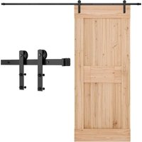
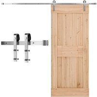
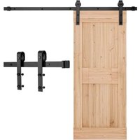
SIMPLE SLIDING BARN DOOR HARDWARE KI
MODEL:5FT-2D-5K-H/5FT-2D-5K-Y/6FT-2D-5K-H/
6FT-2D-5K-Y/6.6FT-2D-5K-H/6.6FT-2D-5K-Y/
8FT-2D-6K/8FT(J)Single Door/8FT(I)Single Door/
10FT-3D-7K-J/10FT-3D-7K-I
We continue to be committed to provide you tools with competitive price. "Save Half", "Half Price" or any other similar expressions used by us only represents an estimate of savings you might benefit from buying certain tools with us compared to the major top brands and does not necessarily mean to co all categories of tools offered by us. You are kindly reminded to verify carefully when you are placing an order with us if you are actually Saving Half in comparison with the top major brands.
MODEL:5FT-2D-5K-H/5FT-2D-5K-Y/6FT-2D-5K-H/6FT-2D-5K-Y/6.6FT-2D-5K-H/6.6FT-2D-5K-Y/8FT-2D-6K/8FT(J)Single Door/8FT(I)Single Door/10FT-3D-7K-J/10FT-3D-7K-I
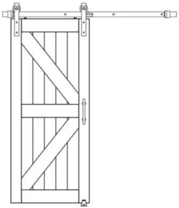
natural_image
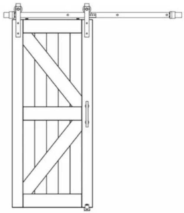
Line drawing of a wooden double door with diagonal bracing and vertical supports (no text or symbols)NEED HELP? CONTACT US!
Have product questions? Need technical support? Please feel free to contact us:
Technical Support and E-Warranty Certificate www.vevor.com/support
This is the original instruction, please read all manual instructions carefully before operating. VEVOR reserves a clear interpretation of user manual. The appearance of the product shall be subject to product you received. Please forgive us that we won't inform you and there are any technology or software updates on our product.
SAFETY INSTRUCTIONS
WARNING:
Read this material before using this product. Failure to do so can re serious injury.
Assembly precautions
- Assemble only according to these instructions. Improper assembly can create hazards.
- Wear ANSI-approved safety goggles and heavy-duty work gloves du assembly.
- Keep assembly area clean and well lit.
- Keep bystanders out of the area during assembly.
- Do not assemble when tired or when under the influence of alcohol drugs or medication.
- Product capabilities apply to properly and completely assembled product only.
- For additional information regarding the parts listed in the following pages, please refer to the Assembly Diagram of this manual. Unwrap separate all parts in a clean work area.
- For safety reasons, This hardware is recommended to be installed by 2 people
- Products are installed away from children and pets;
Use precautions
- This product is not a toy. Do not allow children to play with this
- Use as intended only.
- Inspect before every use; do not use if parts are loose or damage
SAVE THESE INSTRUCTIONS
Product Suitability
The box does not contain door panels and other wooden squares, while require additional purchase
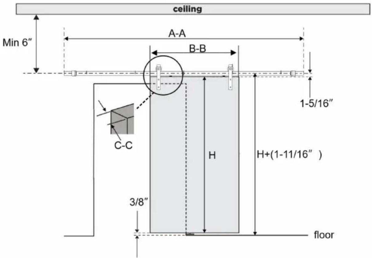
| Model | rail length A-A | Door width B-B | Door thickness C-C |
| 5FT-2D-5K-H | 5ft(1500mm) | ≤30inch | 1-3/8" to 1-3/4" |
| 5FT-2D-5K-Y | |||
| 6FT-2D-5K-H | 6ft(1830mm) | ≤36inch | 1-3/8" to 1-3/4" |
| 6FT-2D-5K-Y | |||
| 6.6FT-2D-5K-H | 6.6ft(2000mm) | 36-40inch | 1-3/8" to 1-3/4" |
| 6.6FT-2D-5K-Y | |||
| 8FT-2D-6K | 8ft(2440mm) | 42-48inch | 1-3/8" to 1-3/4" |
| 8ft(j)single door | |||
| 8ft(I)single door | |||
| 10FT-3D-7K-J | 10ft(3000mm) | ≤60inch | 1-3/8" to 1-3/4" |
| 10FT-3D-7K-I |
The remaining dimensions:
- Product is applicable to the single sliding door, the door height is H depending on the height you purchase;
- The track center to the ground height needs to be 1.6875 inches h than the door height;
- The distance of the track center from the ceiling is not less than 6
- The distance between the bottom side and the bottom side is 0.375 inches
Parameter List
| Model | Product color | hanger type | Orbit split number | Number of rail mounting holes |
| 5FT-2D-5K-H | black | J mould | 2pcs | 5pcs |
| 5FT-2D-5K-Y | Dark silver | |||
| 6FT-2D-5K-H | black | |||
| 6FT-2D-5K-Y | Dark silver | |||
| 6.6FT-2D-5K-H | black | |||
| 6.6FT-2D-5K-Y | Dark silver | |||
| 8FT-2D-6K | Dark silver | J mould | 2pcs | 6pcs |
| 8ft(j)single door | black | J mould | ||
| 8ft(I)single door | black | I mould | ||
| 10FT-3D-7K-J | black | J mould | 3pcs | 7pcs |
| 10FT-3D-7K-I | I mould |
Parts list
Same number of parts
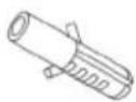
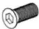
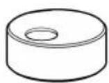 A:Anti-jumpblock×2pcs A:Anti-jumpblock×2pcs | 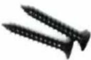 B:M4×25countersunk headtapping screw×2pcs B:M4×25countersunk headtapping screw×2pcs | 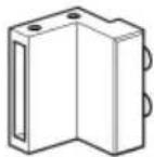 C:DoorStopper × 2pc C:DoorStopper × 2pc | 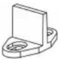 D:T shapeFloor Guide× 1pc D:T shapeFloor Guide× 1pc |
 E:φ6×30 Plasticexpansion bolt ×2pcs E:φ6×30 Plasticexpansion bolt ×2pcs | 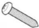 F:M4×25 Roundhead tapping screw×2pcs F:M4×25 Roundhead tapping screw×2pcs | 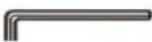 G:2.5mm HexKey × 1pc G:2.5mm HexKey × 1pc |  H:WallSpacer×4 H:WallSpacer×4 |
 K:M10×55 bolt×4 K:M10×55 bolt×4 | 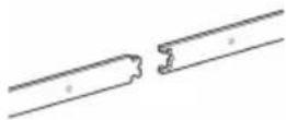 L:Rail Kit × 1pc L:Rail Kit × 1pc |
Parts with different quantities
| Model | 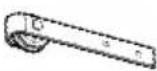 J:Hanger-J J:Hanger-J |  O:washers O:washers | P:M8×90Screw | 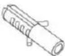 Q:φ12×50Plasticexpansionbolt Q:φ12×50Plasticexpansionbolt |  M:WallSpacer M:WallSpacer |
| 5FT-2D-5K-H | 2 | 13 | 5 | 5 | 5 |
| 5FT-2D-5K-Y | |||||
| 6FT-2D-5K-H | |||||
| 6FT-2D-5K-Y | |||||
| 6.6FT-2D-5K-H | |||||
| 6.6FT-2D-5K-Y | |||||
| 8FT-2D-6K | 2 | 14 | 6 | 6 | 6 |
| 8ft(j)single door | |||||
| 8ft(I)Single Door | 0 | ||||
| 10FT-3D-7K-J | 2 | 15 | 7 | 7 | 7 |
| 10FT-3D-7K-I | 0 | ||||
| The following are the model 8FT-2D-6K, 8ft(j)single door, 8ft(I);Door only available accessories | |||||
 R:M6*10 bolt×4pcs R:M6*10 bolt×4pcs | 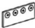 S:connection strap×1pc S:connection strap×1pc | 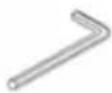 T:4mm Hex ×1pc T:4mm Hex ×1pc | |||
The following are the model 10FT-3D-7K-I and 8ft(I)Single Doc available accessories`
I:Hanger-I×2
Decomposition Diagram Of Model 6ft-2d-5k-h
Note: The remaining model decomposition plots are similar
CNOAUTION
Mishandling of heavy objects (i.e.,doors) may cause a loss of balance serious injury. Always be sure you have a secure
hold on the object and are balanced before moving the object. Always safety shoes when lifting heavy objects.
Getting body parts (i.e., hair, fingers) caught in moving parts may cause pinching and serious injury. Do not put fingers in parts that may move always remove or contain anything on your body that may become entangled with a moving part.
Closing sliding doors with your hand on the end of the door may re your hand, or fingers, getting caught between the door and other soli objects (i.e., another door, molding) causing serious injury. Always use door handle to close door
Usage Statement
Use of excessive force when opening and closing the door(s) may re damage to the hardware. Always hold the handle to gently move the door(s).
Tools required
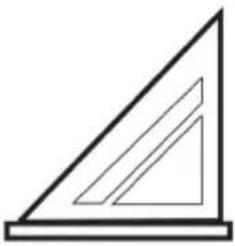 Speed Square Speed Square | 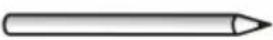 Pencil Pencil |  PhillipsScrewdriver PhillipsScrewdriver | 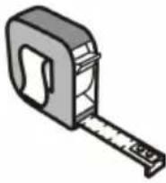 Tape Tape |
 Wrench Wrench | 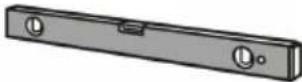 Level Level | 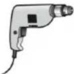 Drill Drill | 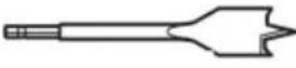 3/8"Drill Bit 3/8"Drill Bit |
 29/64"Drill Bit 29/64"Drill Bit | 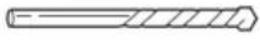 7/32"Drill Bit 7/32"Drill Bit |
Product Assembly
It is very important to determine whether you need to install a Head Board before you install the track.
IF you meet the following situations, we highly recommend you using Header Board.
- IF your wall studs are not 16" on center which won't line up with rail(our rail comes with pre-drilled holes every 16" on center)
- IF your wall type is non-concrete wall, is drywall or other wall type may not support the weight of the track and mounted door)
- IF there is a doorway trim
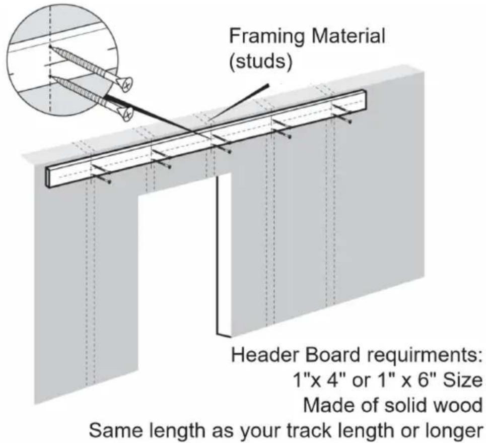
Attention: Header Board & the screws to install header board are included. You can buy them online or offline.
Step-1
1.1. Use a Level and Tape Measure to mark the center line of the tr shown in the product selection diagram, the height of the door is H in
picture above, the height of the center line(measuring up from the flo the height of your door PLUS 1-11/16".
1.2. Position the track in place by the marked center line, ensuring it and use the track as a template to mark mounting holes location for track with a pencil.
See installation tip below.
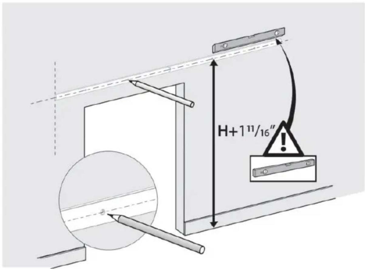
The track needs to fully cover the door openings on the wall panels; suggest that one end of the track is flush with the opening of the v this is related to the width of the door.
INSTALLATION TIP:
To mark the holes more conveniently, you could install track with one bolt without spacer, which helps fix one end of the track. And then move the free end to ensure the track level to mark mounting holes. You can also refer to the track size to mark the position of the track.
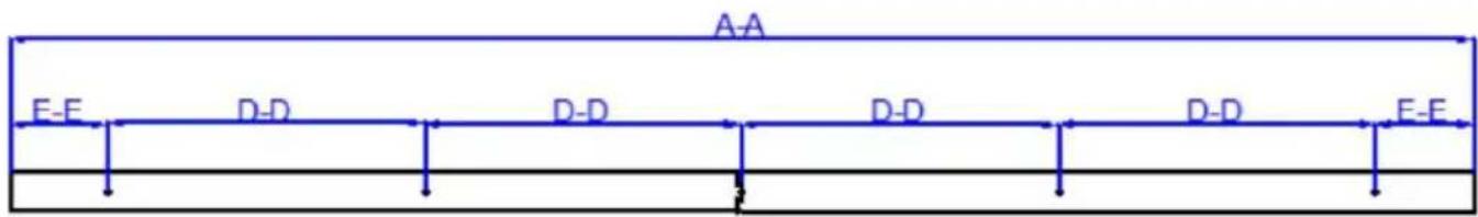
| Model | rail length A-A | rail hole distance D-D | rail side hol and rail edg E-E | Number of marked holes |
| 5FT-2D-5K-H | 5ft(1500mm) | 325mm | 100mm | 5pcs |
| 5FT-2D-5K-Y | ||||
| 6FT-2D-5K-H | 6ft(1830mm) | 406mm | 103mm | 5pcs |
| 6FT-2D-5K-Y | ||||
| 6.6FT-2D-5K-H | 6.6ft(2000mm) | 406mm | 188mm | 5pcs |
| 6.6FT-2D-5K-Y |
The rail mounting holes of model 8FT-2D-6K ,8ft(J)single door and 8ft(I)single door are as follows,six holes;
The rail mounting dimensions for model-FT-3D-7K-J and 10FT-3D-7K-I are as follows, seven holes;
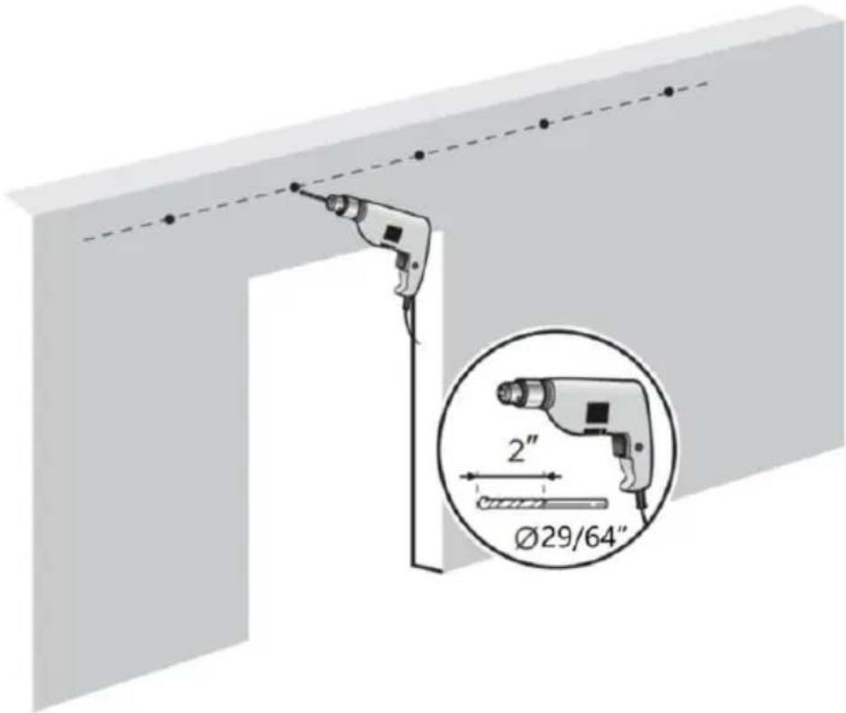
Step-2:
2.1. Use a Φ29/64"drill hole in the marked position, 2 inches deep;
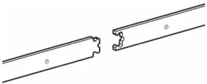
Step-3: Install the guide rail
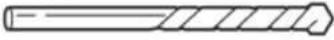
3.1.The 2 guide of model 8FT-2D-6K is combined by connection strap 4 bolts;
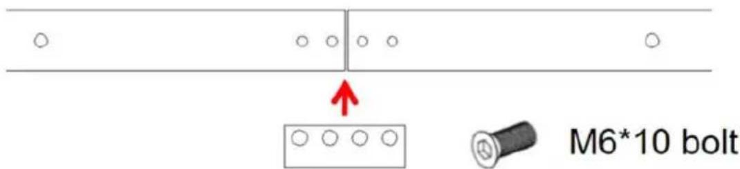
The remaining models are flower-shaped combinations via the rail.
natural_image
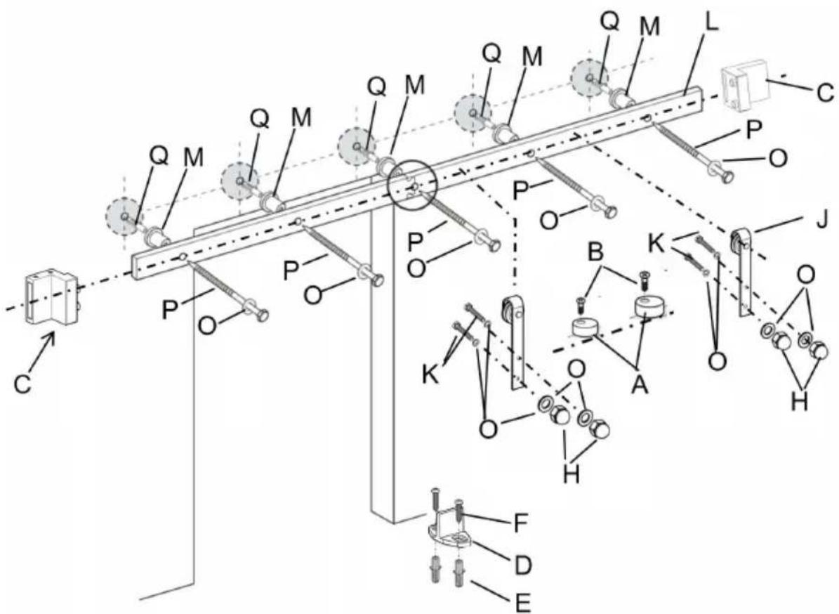
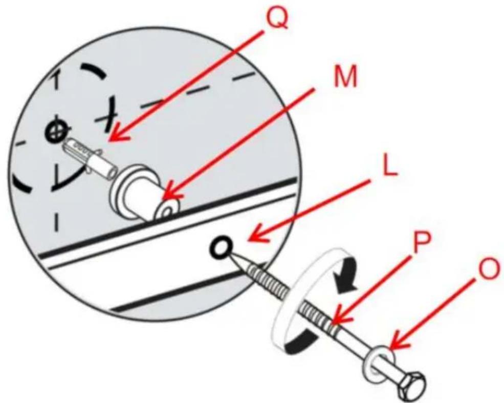
Pure technical line drawing of two mechanical components with no text or symbols3.2. Concrete wall Installation.
Install the Plastic expansion bolt Q to holes on the concrete wall first use screw P through the washers O, rail L and Wall Spacer M, and lock on Plastic expansion bolt Q.
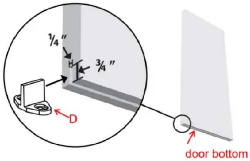
Step-4
Use router or circular saw to create a kerf at bottom of the door, a center to allow the tip of the T-shaped floor guide to fit in between. The floor guide is used to keep your door stable and prevent the do bottom swinging back and forth when you slide it open and closed.
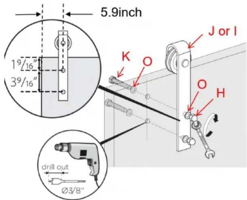
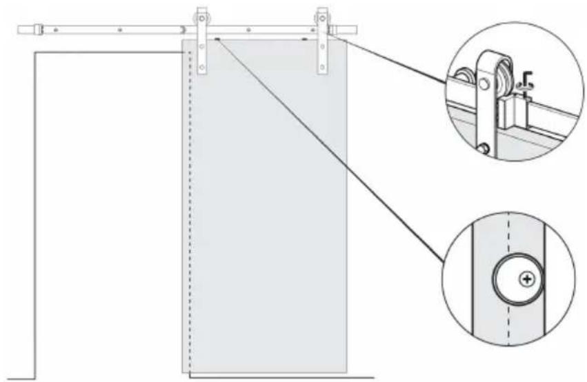
Step-5
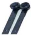
According to the following figure, use the bolt K to pass through the O, door, Hanger J, washer O, and finally tighten the bolt H with the secure the Hanger J on the top of the door; install the hangers on the door ,Make sure the bolt K are located in the middle line of the side.
Each Hanger requires two Bolts;2 hangers are required for each door.
Note: The Hanger for the Model 10FT-3D-7K-I is the Hanger I. If your door thickness is 1-3/4 inch, you do not need to install O.
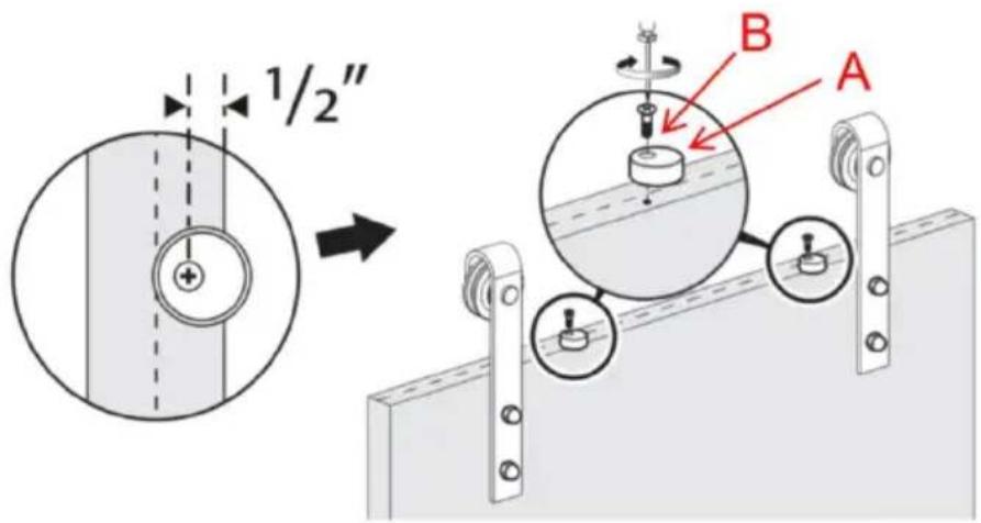
Step-6
The anti-jump blocks are used to protect the door from touching the when sliding the door.
First, mark at 0.5inch from the edge of the door, then let the screw Anti-jump block A to align the mark, use the screw B through Anti-ju block A, and lock at the mark.
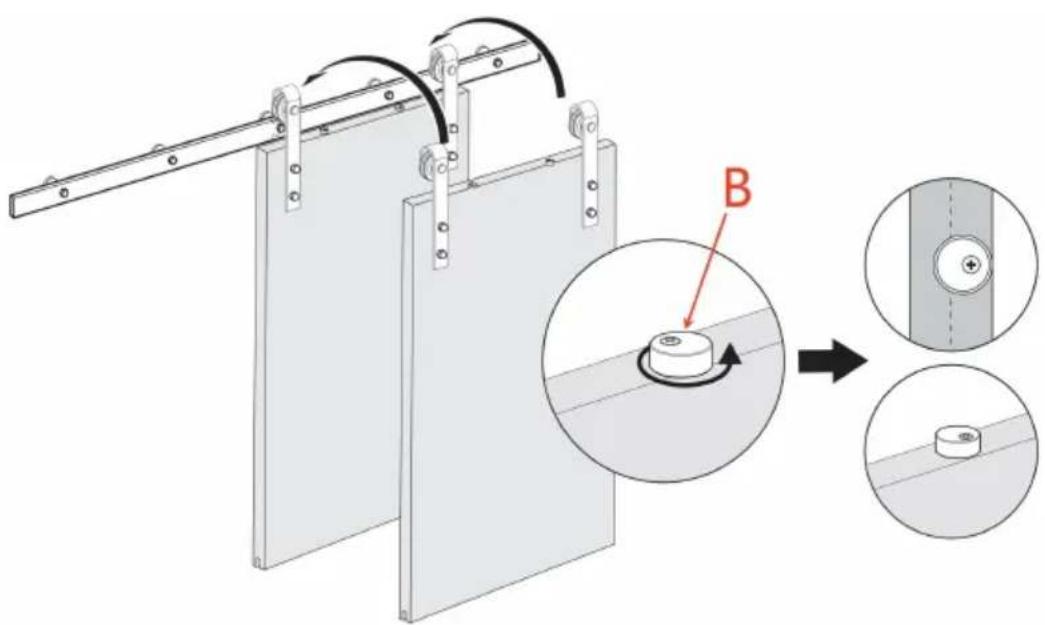
Step-7
Hang the door over the track and rotate the anti-jump blocks 180°
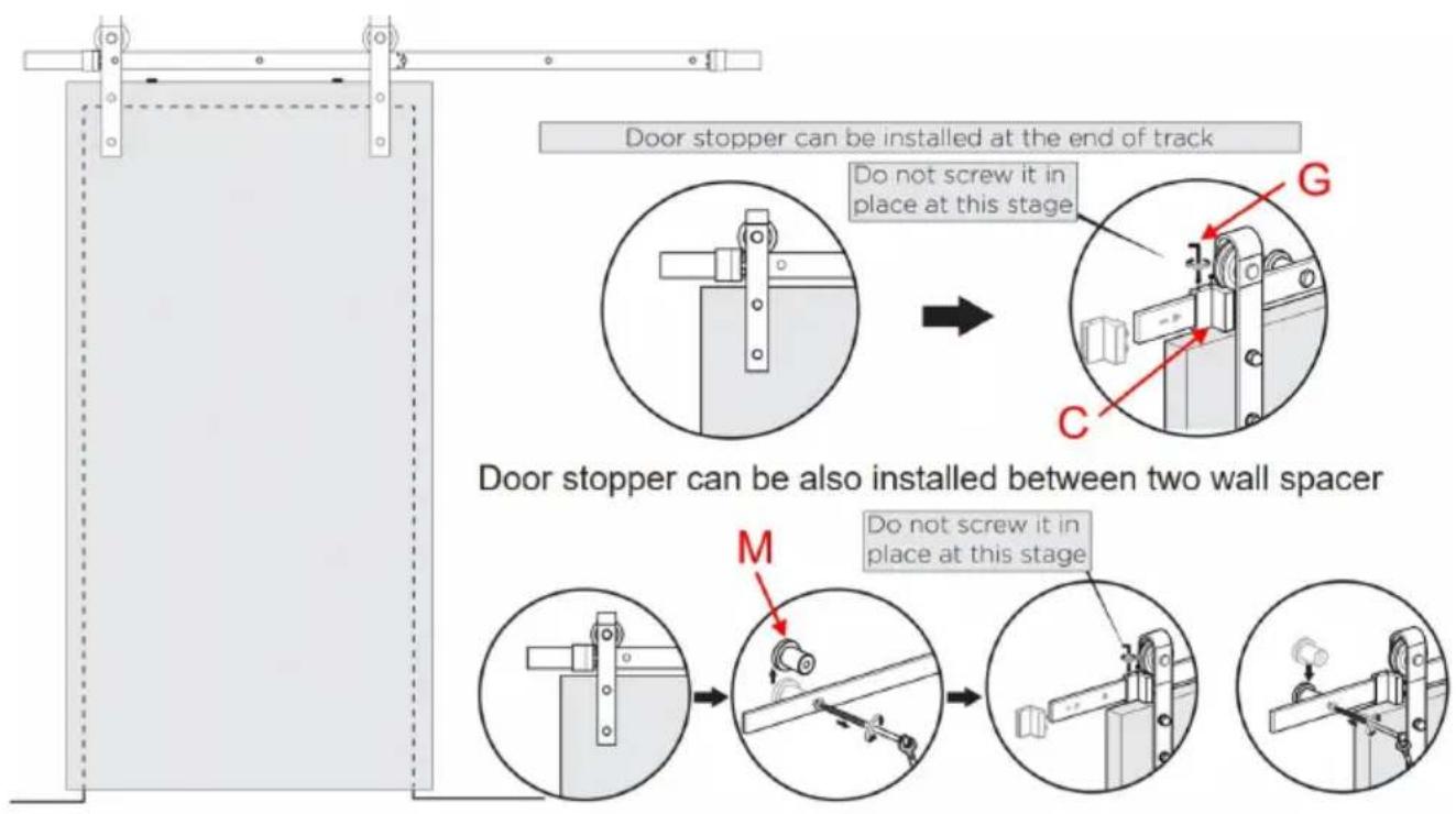
Step-8
Slide door stoppers C on both ends of track.
Slide door back and forward to test how well the door covers the o Reposition door stoppers as you need. Adjust the position of the left right door stopper when the door is open and closed.If you reduce the trip, the door stoppers C can move toward the middle of the rail.
When door stoppers C is blocked by wall spacer M and unable to r you can remove wall spacer M, move to the appropriate position and install door stoppers M back to the original position.
Door stopper can be also installed between two wall spacer
Step-9
Final Check of door stoppers and Anti-jump blocks.
Check the door stoppers are properly located and tightened in place Hex Key G.
Also check the anti-jump blocks are rotated correctly and tightened.
natural_image
Technical diagram of a sliding door mechanism with two views of the handle (no text or symbols present)Step-10
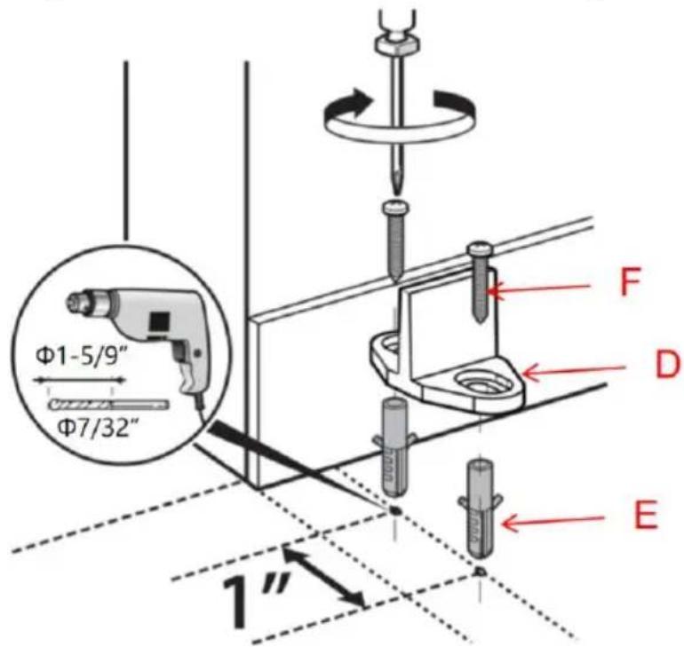
Install the floor guide D.
10.1. Put the floor guide on the floor first to a suitable position, sliding door so that the tip of the floor guide can work well in the slot of of the door. And then mark 2 holes of the floor guide. Then two sections through floor guide mark two points on the floor.
10.2. Use 7 / 32" drill bit to drill holes with a depth of 1.375inch on the floor mark; Then put Plastic expansion bolt E into the floor hole; Screw F through the screw hole of floor guide D and installed in Plastic expa bolt E to complete the installation of floor guide D.
Manufacturer: Shanghaimuxinmuyeyouxiangongsi
Address: Shuangchenglu 803nong11hao1602A-1609shi, baoshanqu, shanghai 200000 CN.
Imported to AUS: SIHAO PTY LTD. 1 ROKEVA STREETEASTWOOD
NSW 2122 Australia
Imported to USA: Sanven Technology Ltd. Suite 250, 9166 Anaheim
Place, Rancho Cucamonga, CA 91730
| UK | REP |
YH CONSULTING LIMITED. C/O YH Consultin
Limited Office 147, Centurion House, London
Road, Staines-upon-Thames, Surrey, TW18 4A>
| EC | REP |
E-CrossStu GmbH
Mainzer Landstr.69,
60329 Frankfurt am Main.
VEVOR®
TOUGH TOOLS, HALF PRICE
Technical Support and E-Warranty Certificate
www.vevor.com/support
VEVOR®
TOUGH TOOLS, HALF PRICE
MODÈLE : 5 PI-2D-5K-H/5 PI-2D-5K-Y/6 PI-2D-5K-H/
6 PI-2D-5K-Y/6,6 PI-2D-5K-H/6,6 PI-2D-5K-Y/
8FT-2D-6K/8FT(J)Porte simple/8FT(I)Porte simple/
10FT-3D-7K-J/10FT-3D-7K-I
MODÈLE : 5 PI-2D-5K-H/5 PI-2D-5K-Y/6 PI-2D-5K-H/6 PI-2D-5K-Y/
6,6 pi-2D-5K-H/6,6 pi-2D-5K-Y/8 pi-2D-6K/8 pi (J) porte simple/8 pi (I) porte simple/10 pi-3D-7K-J/10 pi-3D-7K-I
natural_image
Technical line drawing of a door frame with diagonal bracing and support brackets (no text or symbols)BESOIN D'AIDE? CONTACTEZ-NOUS!
Header Board requirements:
1"x 4" or 1"x 6" Size
Made of solid wood
Same length as your track length or longer
Étape 2 :
natural_image
Technical line drawing of two mechanical components with no visible text or symbolsÉtape 4
Étape 6
Étape 8
Étape 9
natural_image
Technical diagram of a mechanical latch or guard system with two views of the latch mechanism (no text or symbols present)Étape 10
YH CONSULTING LIMITED. C/O YH Consulting Limited Bureau 147, Centurion House, London Road, Staines-upon-Thames, Surrey, TW18 4AX
E-CrossStu GmbH
Mainzer Landstr.69,
natural_image
Technical line drawing of a door frame with diagonal bracing and support brackets (no text or symbols)Header Board requirements:
1"x 4" or 1"x 6" Size
Made of solid wood
Same length as your track length or longer
Schritt 2:
natural_image
Technical line drawing of two mechanical components with no visible text or symbols3.2.Betonwandinstallation.
Schritt
Schritt
Schritt 8
Schritt 9
natural_image
Technical diagram of a mechanical assembly with two views: one showing a sliding mechanism and the other showing a circular component (no text or symbols present)Schritt 10:
YH CONSULTING LIMITED. C/O YH Consulting Limited Office 147, Centurion House, London Road, Staines-upon-Thames, Surrey, TW18 4AX
www.vevor.com/support
VEVOR®
TOUGH TOOLS, HALF PRICE
natural_image
Technical line drawing of a door frame with diagonal bracing and horizontal railings (no text or symbols)Fase 2:
natural_image
Pure technical line drawing of two mechanical components with no text or symbolsFase 4
Fase 6
Passo 8
Passo 9
natural_image
Technical diagram of a sliding door mechanism with two views of the handle (no text or symbols)Fase 10
Importato in AUS: SIHAO PTY LTD. 1 ROKEVA STREETEASTWOOD NSW 2122 Australia
Importato negli USA: Sanven Technology Ltd. Suite 250, 9166 Anaheim Place, Rancho Cucamonga, CA 91730
YH CONSULTING LIMITED. C/O YH Consulting Limited Ufficio 147, Centurion House, London Road, Staines- upon-Thames, Surrey, TW18 4AX
elettronica www.vevor.com/support
VEVOR®
TOUGH TOOLS, HALF PRICE
natural_image
Technical line drawing of a door frame with diagonal bracing and horizontal railings (no text or symbols)www.vevor.com/support
Paso 2:
natural_image
Pure technical line drawing of two mechanical components with no text or symbolsPaso 4:
Paso 6
Paso 8
Paso 9
natural_image
Technical diagram of a mechanical latch or slide assembly with two views of the latch mechanism (no text or symbols present)Paso 10
Road, Staines-upon-Thames, Surrey, TW18 4AX
E-CrossStu GmbH
Mainzer Landstr.69,
natural_image
Technical line drawing of a door frame with diagonal bracing and support brackets (no text or symbols)POTRZEBUJESZ POMOCY? SKONTAKTUJ SIE Z NAMI!
| Model | długość szyny AA | Szerokość drzwi | Grubość drzwi DK |
| 5FT-2D-5K-H | 5 stóp (1500 mm) | 30 cali | 1-3/8" do 1-3/4" |
| 5FT-2D-5K-Y | |||
| 6FT-2D-5K-H | 6 stóp (1830 mm) | 36 cali | 1-3/8" do 1-3/4" |
| 6FT-2D-5K-Y | |||
| 6,6FT-2D-5K-H | 6,6 stopy (2000 mm) | 36-40 cali | 1-3/8" do 1-3/4" |
| 6,6FT-2D-5K-Y | |||
| 8FT-2D-6K | 8 stóp (2440 mm) | 42-48 cali | 1-3/8" do 1-3/4" |
| 8ft(j) pojedyncze drzwi | |||
| 8ft(I) pojedyncze drzwi | |||
| 10FT-3D-7K-J | 10 stóp (3000 mm) | 60 cali | 1-3/8" do 1-3/4" |
| 10FT-3D-7K-I |
Pozostałe wymiary:
Header Board requirements:
1"x 4" or 1"x 6" Size
Made of solid wood
Same length as your track length or longer
Krok 2:
natural_image
Technical line drawing of two mechanical components with no visible text or symbolsKrok 4
Krok 6
Krok 8
Krok 9
natural_image
Technical diagram of a mechanical assembly with two views: one showing a sliding mechanism and the other showing a circular component (no text or symbols present)Krok 10
YH CONSULTING LIMITED. C/O YH Consulting Limited Biuro 147, Centurion House, London Road, Staines-upon-Thames, Surrey, TW18 4AX
| Przedstaw ciel UE |
E-CrossStu GmbH
Mainzer Landstr.69,
60329 Frankfurt nad Menem.
VEVOR®
TOUGH TOOLS, HALF PRICE
6FT-2D-5K-J/6.6FT-2D-5K-H/6.6FT-2D-5K-J/
8FT-2D-6K/8FT(J)Enkele deur/8FT(I)Enkele deur/
10FT-3D-7K-J/10FT-3D-7K-I
natural_image
Technical line drawing of a door frame with diagonal bracing and horizontal railings (no text or symbols)HULP NODIG? NEEM CONTACT MET ONS OP!
| Model | spoorlengte AA | Deurbreedte BB | Deurdikte CC |
| 5FT-2D-5K-H | 5 voet (1500 mm) | ÿ30 inch | 1-3/8" tot 1-3/4" |
| 5FT-2D-5K-J | |||
| 6FT-2D-5K-H | 6 voet (1830 mm) | ÿ36 inch | 1-3/8" tot 1-3/4" |
| 6FT-2D-5K-J | |||
| 6,6FT-2D-5K-H | 6,6 voet (2000 mm) | 36-40 inch | 1-3/8" tot 1-3/4" |
| 6,6FT-2D-5K-J | |||
| 8FT-2D-6K | 8 voet (2440 mm) | 42-48 inch | 1-3/8" tot 1-3/4" |
| 8ft(j)enkele deur | |||
| 8ft(l)enkele deur | |||
| 10FT-3D-7K-J | 10 voet (3000 mm) | ÿ60 inch | 1-3/8" tot 1-3/4" |
| 10FT-3D-7K-I |
Stap 2:
Stap 3: De geleiderail monteren
natural_image
Technical line drawing of two mechanical brackets with no text or symbolsStap 4
Stap 6
Stap 8
Stap 9
natural_image
Technical diagram of a mechanical latch or slide assembly with two views of the latch mechanism (no text or symbols present)Stap 10
YH CONSULTING LIMITED. C/O YH Consulting Limited Kantoor 147, Centurion House, London Road, Staines- upon-Thames, Surrey, TW18 4AX
E-CrossStu GmbH
Mainzer Landstr.69,
60329 Frankfurt am Main.
VEVOR®
TOUGH TOOLS, HALF PRICE
www.vevor.com/support
VEVOR®
TOUGH TOOLS, HALF PRICE
natural_image
Technical line drawing of a door frame with diagonal bracing and horizontal railings (no text or symbols)BEHÖVER HJÄLP? KONTAKTA OSS!
| Modell | räls längd AA | Dörrbredd BB | Dörrtjocklek CC |
| 5FT-2D-5K-H | 5 fot (1500 mm) | ÿ30 tum | 1-3/8" till 1-3/4" |
| 5FT-2D-5K-Y | |||
| 6FT-2D-5K-H | 6 fot (1830 mm) | ÿ36 tum | 1-3/8" till 1-3/4" |
| 6FT-2D-5K-Y | |||
| 6.6FT-2D-5K-H | 6,6 fot (2000 mm) | 36-40 tum | 1-3/8" till 1-3/4" |
| 6.6FT-2D-5K-Y | |||
| 8FT-2D-6K | 8 fot (2440 mm) | 42-48 tum | 1-3/8" till 1-3/4" |
| 8ft(j) enkeldörr | |||
| 8 fot(I) enkeldörr | |||
| 10FT-3D-7K-J | 10 fot (3000 mm) | ÿ60 tum | 1-3/8" till 1-3/4" |
| 10FT-3D-7K-I |
Steg-2:
Steg-3: Installera styrskenan
natural_image
Technical line drawing of two mechanical components with no visible text or symbolsSteg-4
Steg-6
Steg-8
Steg-9
natural_image
Technical diagram of a mechanical assembly with two views: one showing a sliding mechanism and the other showing a circular component (no text or symbols present)Steg-10
Installera golvguiden D.
YH CONSULTING LIMITED. C/O YH Consulting Limited Office 147, Centurion House, London Road, Staines-upon-Thames, Surrey, TW18 4AX
| EC | REP |
E-CrossStu GmbH
Mainzer Landstr.69,
60329 Frankfurt am Main.
VEVOR®
TOUGH TOOLS, HALF PRICE
www.vevor.com/support