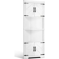
A02D.2058 - Wardrobe Vevor - Free user manual and instructions
Find the device manual for free A02D.2058 Vevor in PDF.


User questions about A02D.2058 Vevor
0 question about this device. Answer the ones you know or ask your own.
Ask a new question about this device
Download the instructions for your Wardrobe in PDF format for free! Find your manual A02D.2058 - Vevor and take your electronic device back in hand. On this page are published all the documents necessary for the use of your device. A02D.2058 by Vevor.
USER MANUAL A02D.2058 Vevor
Technical Support and E-Warranty Certificate www.vevor.com/support
VERTICAL CABINET
MODEL: A02D.2058
We continue to be committed to provide you tools with competitive price. "Save Half", "Half Price" or any other similar expressions used by us only represents an estimate of savings you might benefit from buying certain tools with us compared to the major top brands and does not necessarily mean to cover all categories of tools offered by us. You are kindly reminded to verify carefully when you are placing an order with us if you are actually saving half in comparison with the top major brands.
MODEL: A02D.2058
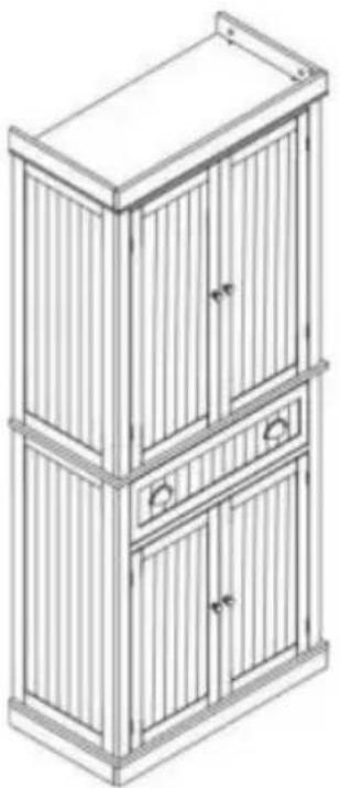
natural_image
Line drawing of a two-tiered cabinet with vertical slats and doors (no text or symbols)NEED HELP? CONTACT US!
Have product questions? Need technical support? Please feel free to contact us:
Technical Support and E-Warranty Certificate
www.vevor.com/support
This is the original instruction, please read all manual instructions carefully before operating. VEVOR reserves a clear interpretation of our user manual. The appearance of the product shall be subject to the product you received. Please forgive us that we won't inform you again if there are any technology or software updates on our product.
 | Warning-To reduce the risk of injury, user must read instructions manual carefully. |
 | Wear eye protection. |
| Wear protective gloves |
SAFETY WARNINGS AND PRECAUTIONS
Thank you for using this product. In order to make sure that you can operate the machine correctly, read this instruction carefully before operation and keep it properly for future reference. Please be sure to read the precautions and safety rules in this page to ensure your safe use. This manual will outline safety warnings and precautions, operating, maintenance and cleaning. The warnings and instructions reviewed in this manual cannot cover all possible conditions and situations that may occur. Caution and common sense are not built into this product, since we believe that the uses will comply with these codes.
Please read ALL the instructions before using your machine.
- Assemble needs to follow these instructions. Incorrect assembly can be a hazard.
- Wear safety goggles and heavy-duty work gloves during assembly.
- Do not assemble when tired or when under the influence of alcohol, drugs or medication.
- Weight and other product properties are only applicable to correctly and completely assembled products.
- Keep the assembly area clean and well-lit.
- Keep bystanders out of the area during assembly.
- This product is not a toy. Do not allow children and pet to play with or approach this item.
- Use as intended only. Do not sit or stand on the product.
- Inspect before every use. Do not use it if parts are loose or damaged.
-
For indoor use only.
-
Do not exceed the listed weight capacity. Tighten all knobs securely before applying load. Be aware of dynamic loading! The sudden load movement may briefly create an excess load, causing product failure.
- Do not apply this unit to any other purposes than the indicated usage.
- Do not use it outdoors or for commercial purposes. INDOOR USE ONLY.
- DO NOT CLEAN IT WITH ANY ABRASIVE MATERIAL.
- Never leave it unattended while in use.
- Pay attention to hand injuries caused by drawer pinching!
- Do not place the product on or near hot air, electric burners or heaters.
- Do not place in a damp environment.
- The product should be placed on a flat surface.
A WARNING: TO PREVENT SERIOUS INJURY AND DEATH FROM TIPPING:
-
Attention: An anti tipping device must be installed to securely secure the product to the wall (Ensure the reliability of the wall itself).
-
This appliance is not intended for use by young or infirm persons unless supervised by a responsible person to ensure that they can use the appliance safely. Young children should be supervised to ensure that they do not play with the product. Children and pets should stay away from the product.
PRODUCT PARAMETERS
| MODEL Loading Capacity | |
| A02D.2058 | Max50Kg (About 110LBS) |
CAUTION:
- Do not place all the weights on the same layer!
- Place the weight evenly on each layer plate to achieve the maximum bearing capacity!
ASSEMBLY STEPS
- Please dispose of all plastic bags carefully and keep them away from children and pet.
- Check all components provided according to the list in this manual. Make sure you have all of the parts listed.
- Whilst every care is taken in the manufacture of this product, care must be taken during assembly in case sharp edges are present.
- Wear eye protection, protective gloves, during assembly and using.
- The product should be placed on a flat surface.
- The product requires two people to assemble.
- The product requires the use of a rubber hammer and a Phillips screwdriver (Rubber hammer and cross screwdriver need to be purchased by oneself).
- If uneven product gaps are found, they can be disassembled and adjusted.
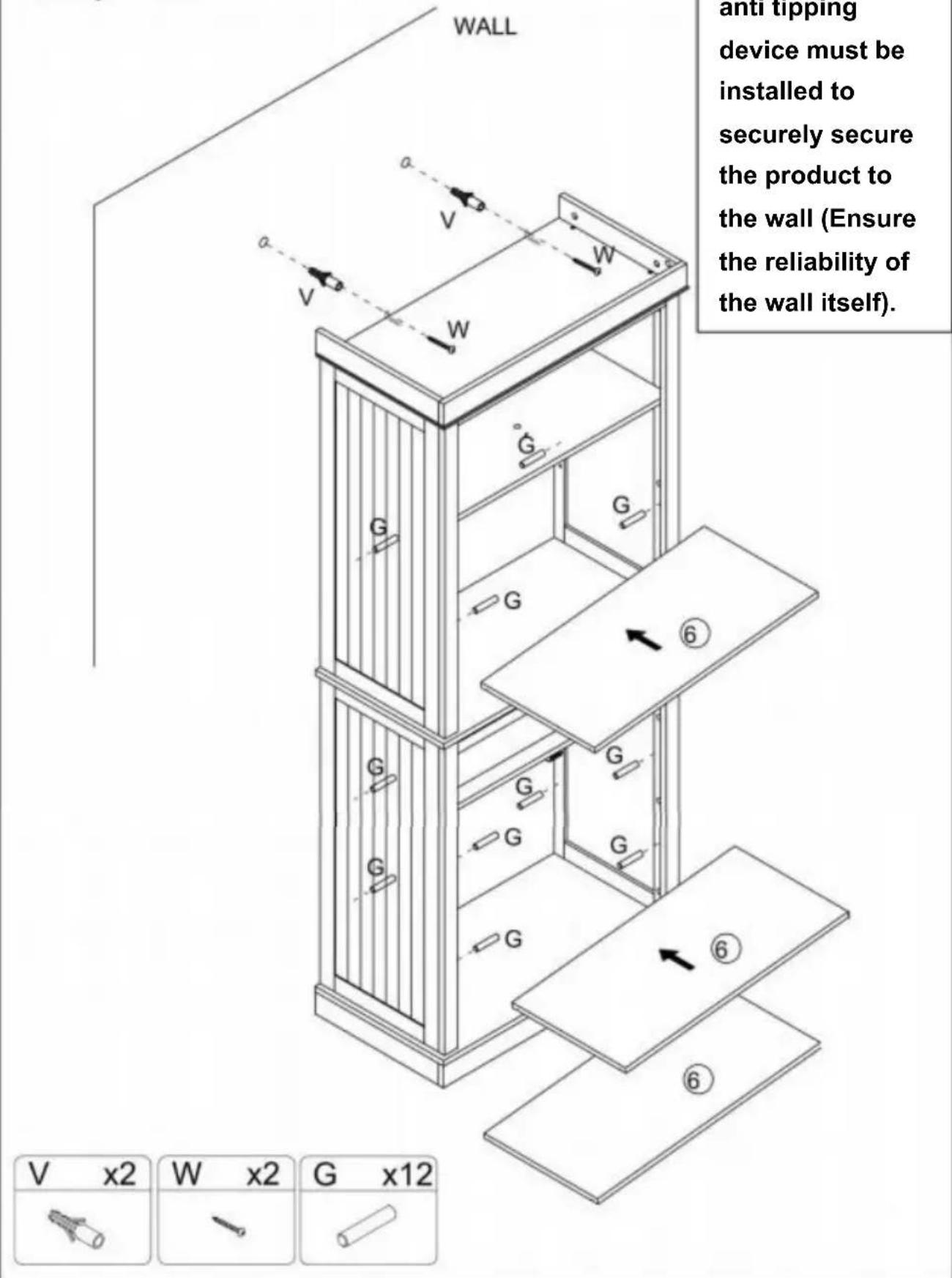
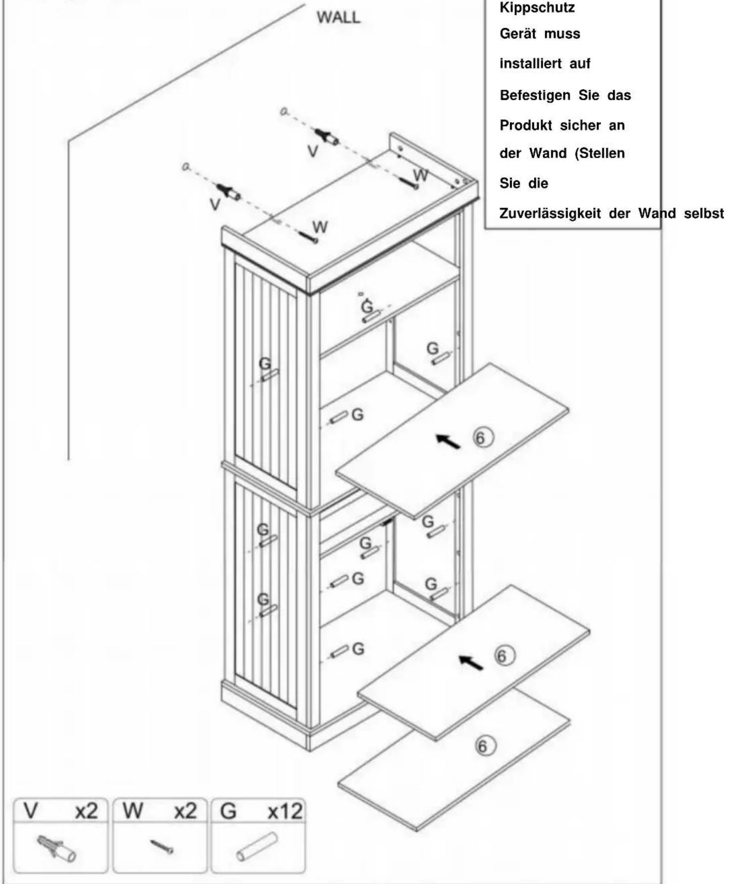
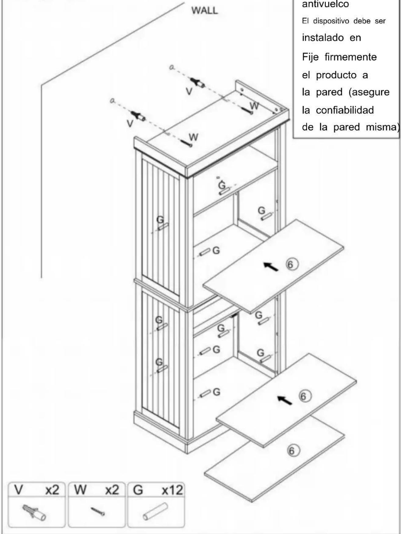
Attention: An anti tipping device must be installed to securely secure the product to the wall (Ensure the reliability of the wall itself).
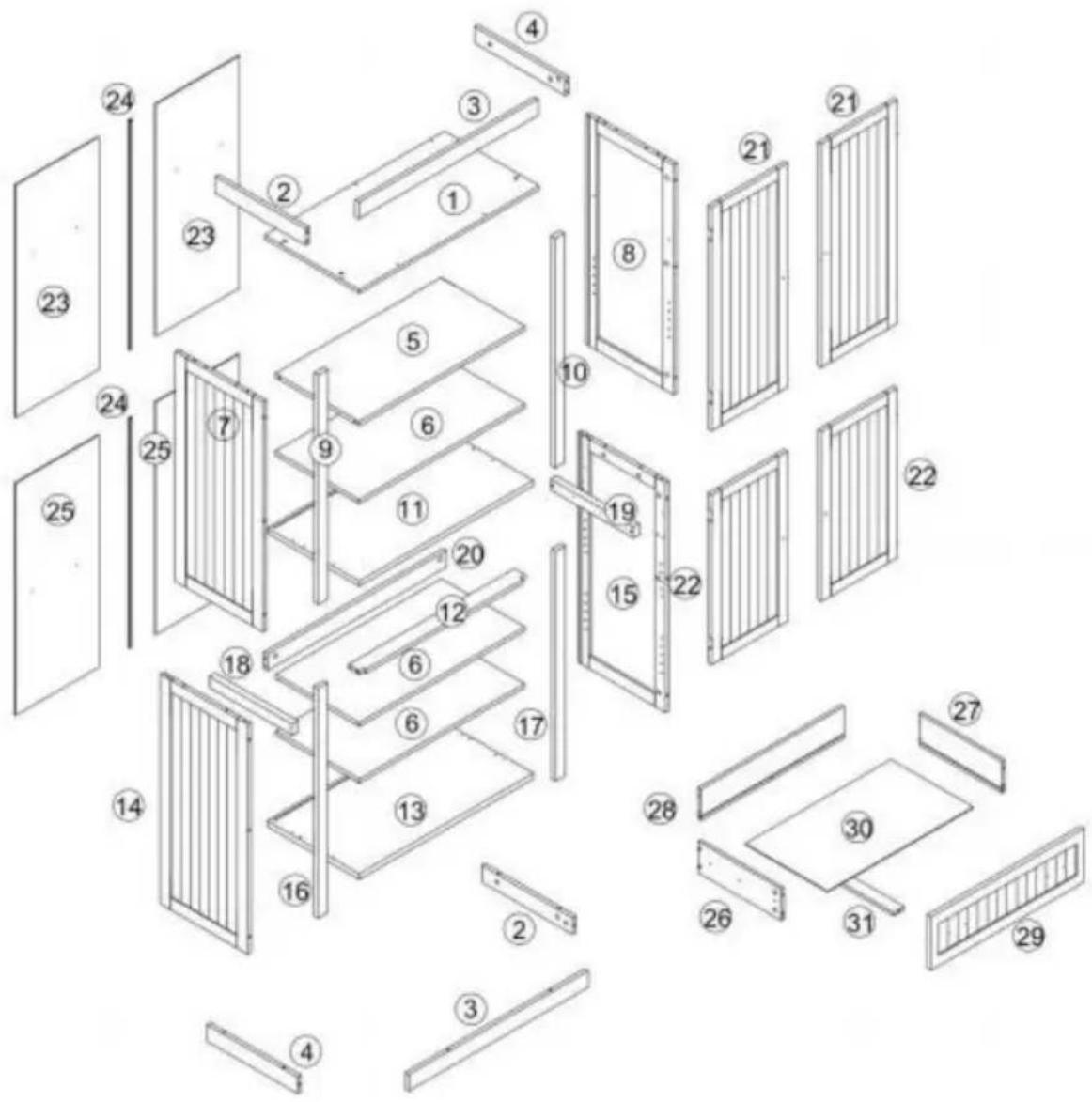
text_image
Exploded view diagram of a multi-panel door assembly with numbered components for identification
text_image
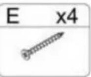
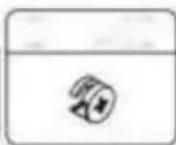
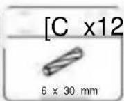
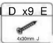
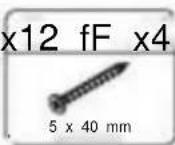
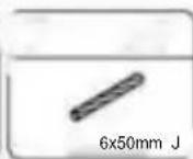
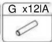
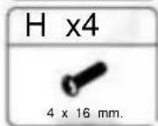
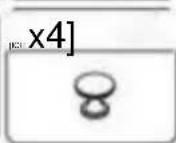
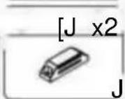
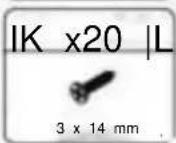
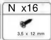
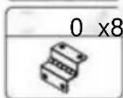
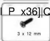
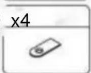
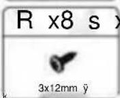
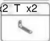
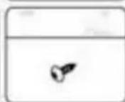
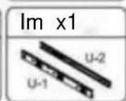
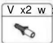
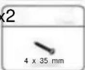
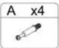
A x45l B x45 [C x12l D x9 E x12 fF x4 G x12l 6x30mm 4x30mm J 5x40mm 6x50mm J H x4 [I x4] [J x2 I K x20 |L x16] M x2 N x16 4x16mm J J 3x14mm 4 O 3.5x12mm 0 x8l P x36] |Q x4 R x8 S x2 T x2 U x1 3x12mm 3x12mm ▲ V x2 W x2 4x35mm Note: the quantity of parts shown in the manual is the actual usage and the unused parts are spare parts.Step 1
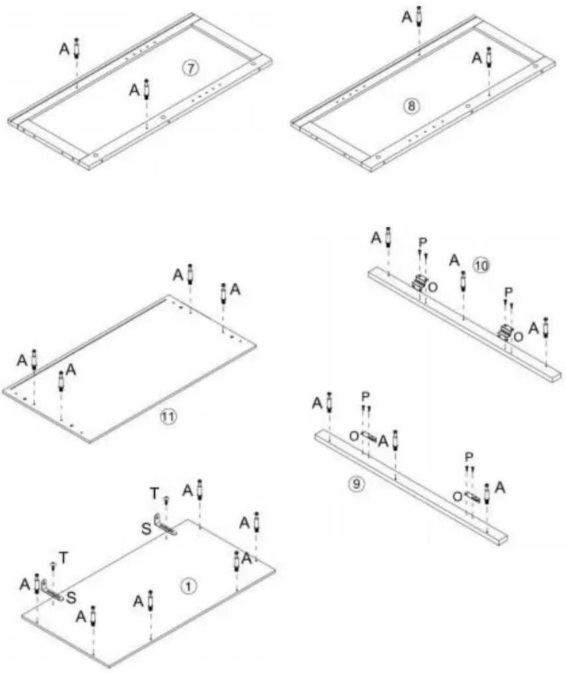
S x2 | T x2 | P x8 | O x4 | A x20 |
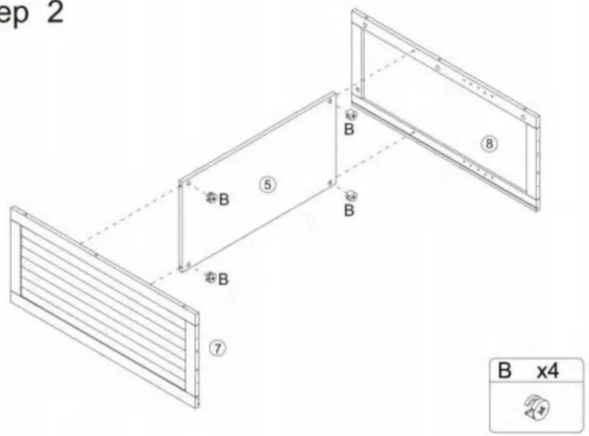
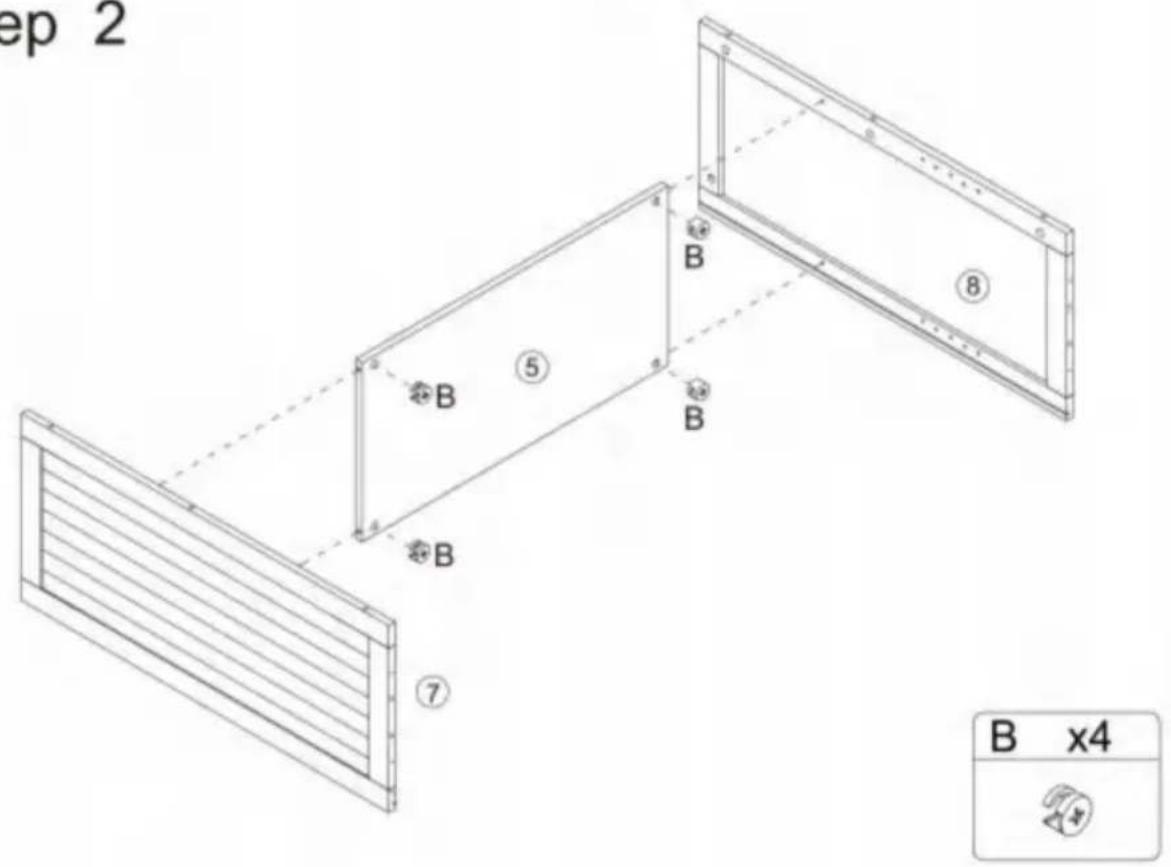
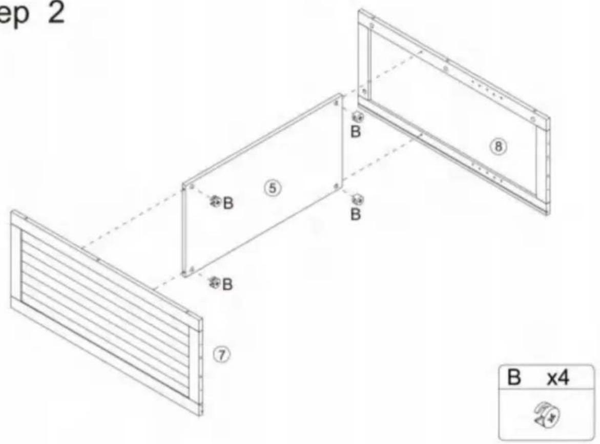
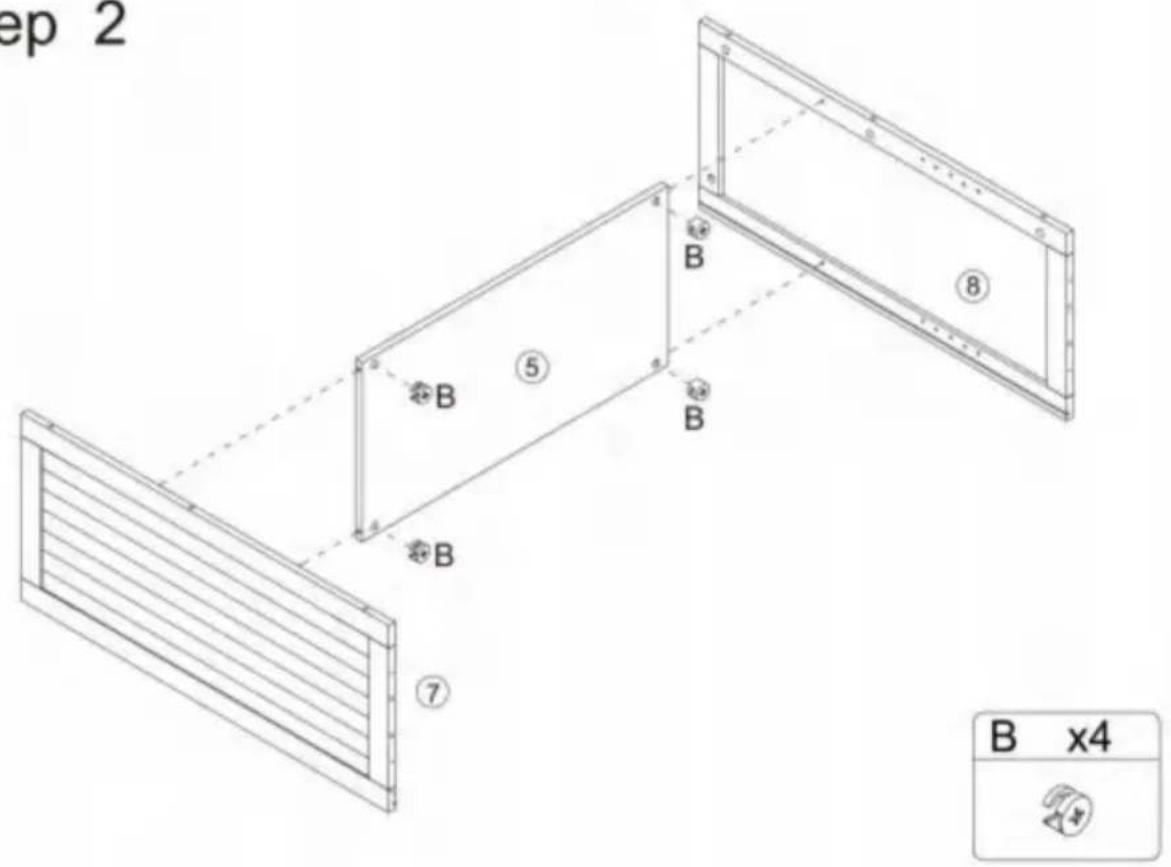
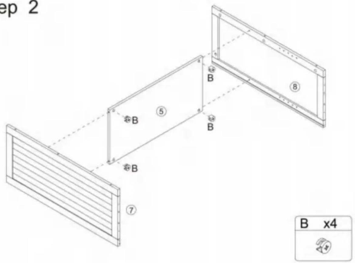
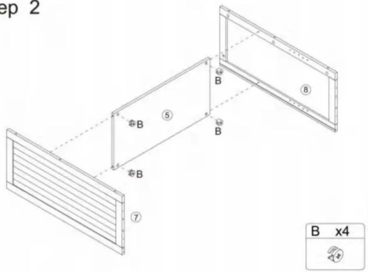
Step 2
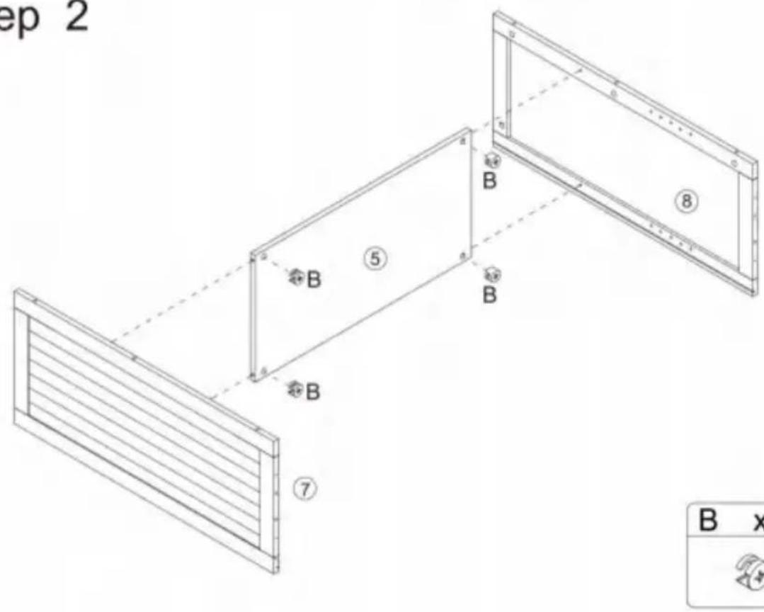
text_image
Technical diagram of a structural frame with labeled components and dimensions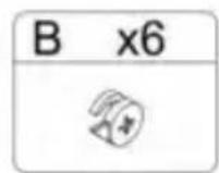
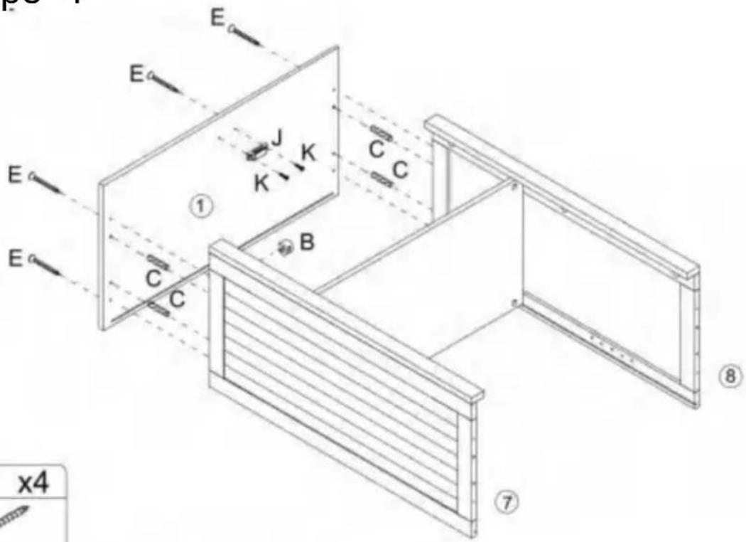
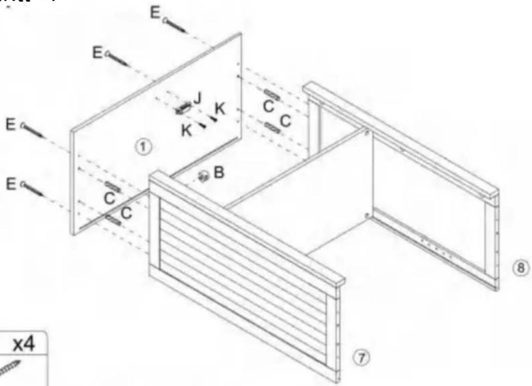
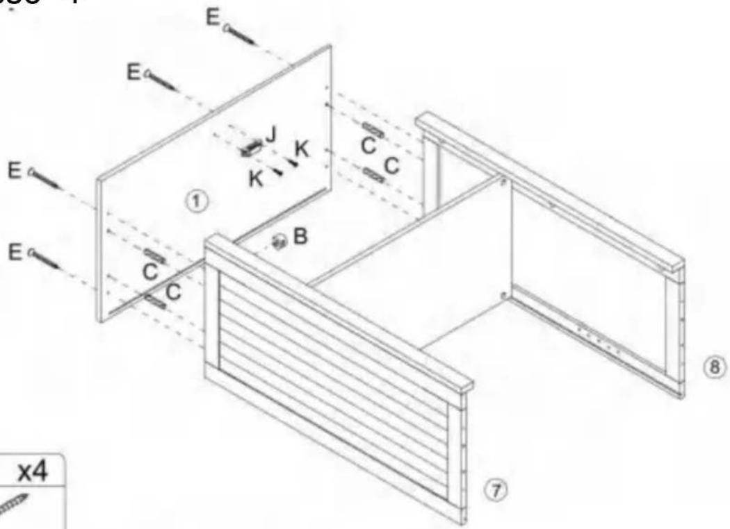
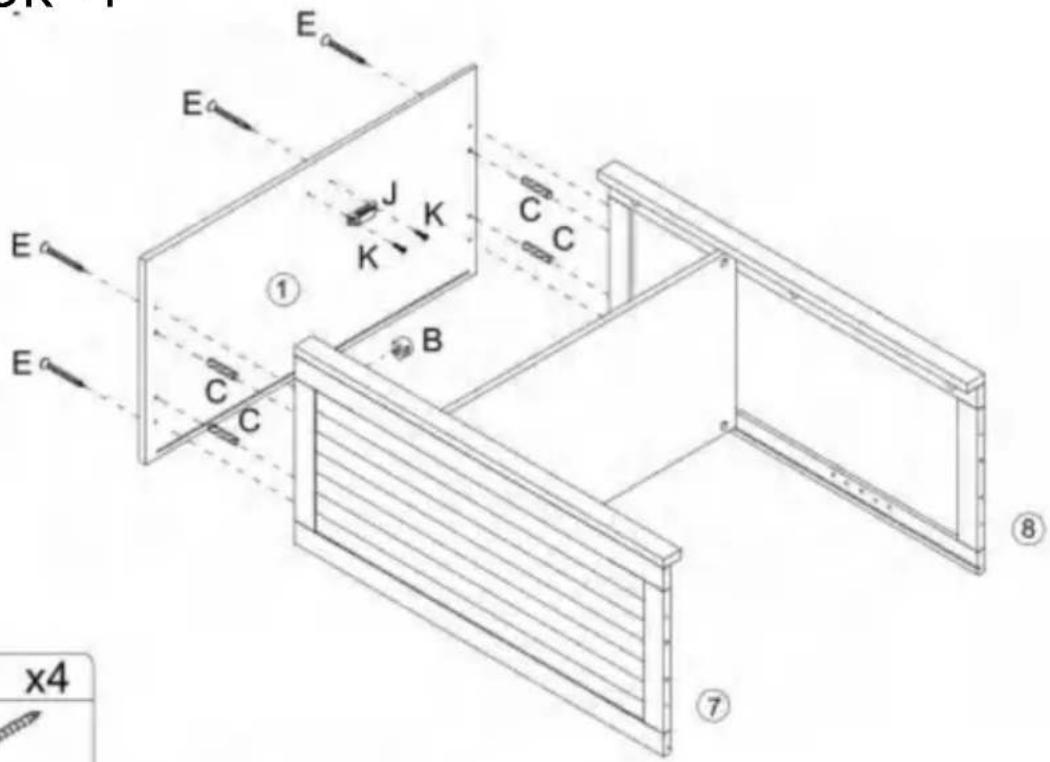
Step 4
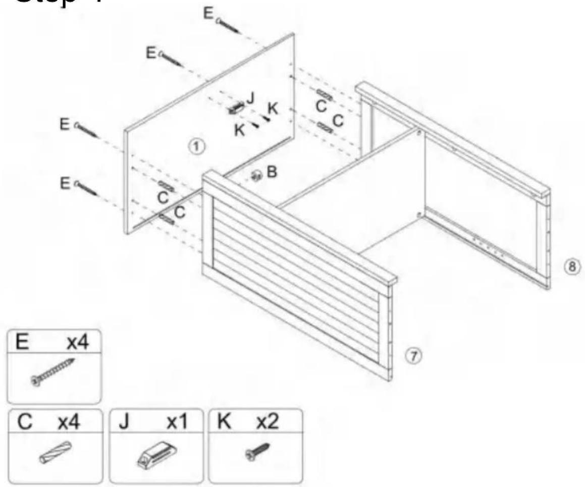
text_image
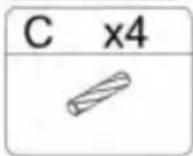
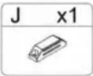
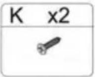
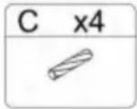
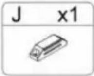
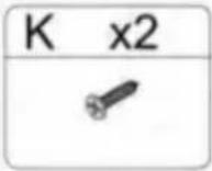
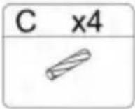
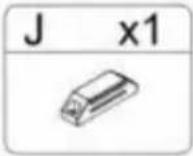
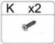
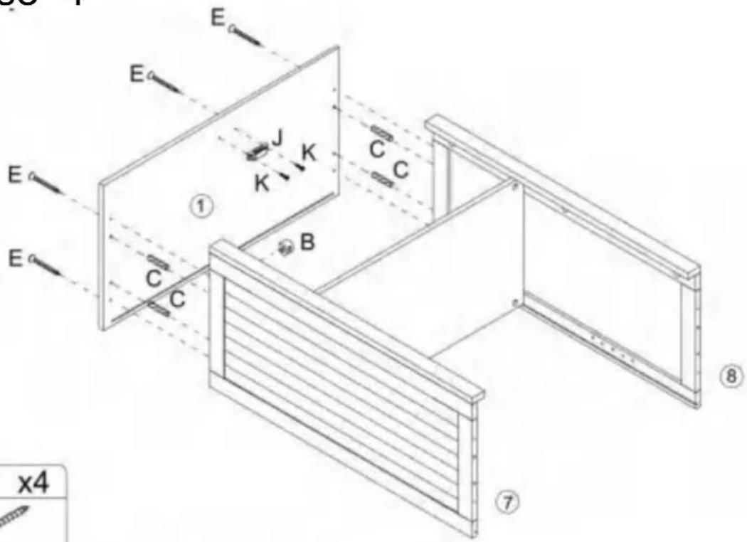
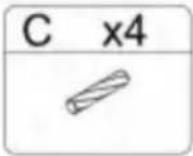
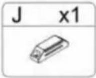
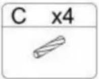
E E E J K C C ① B C C E x4 C x4 J x1 K x2 ⑦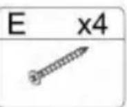
Step 5
text_image
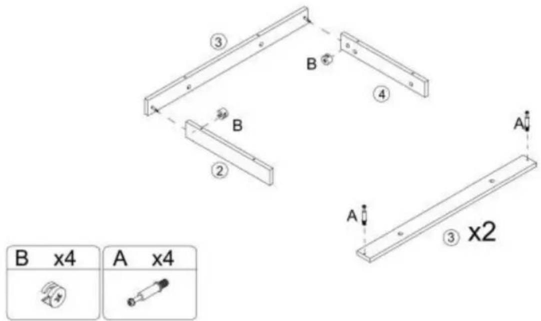
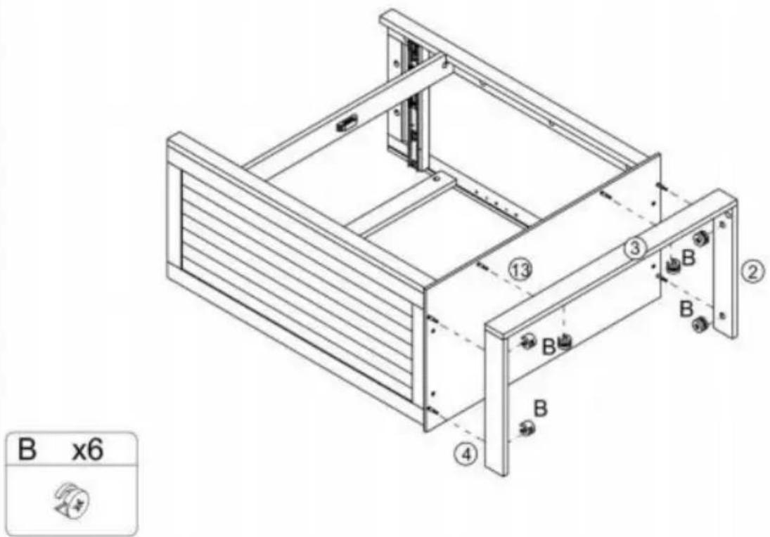
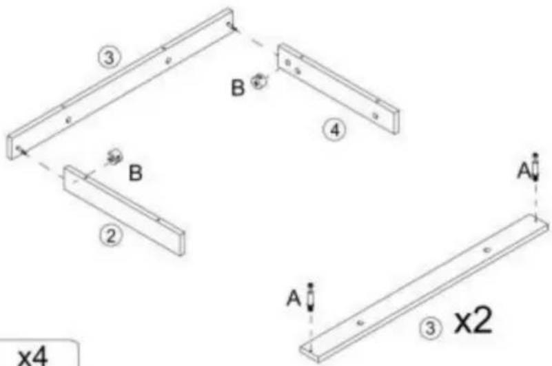
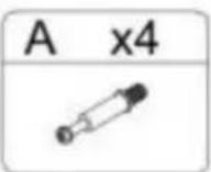
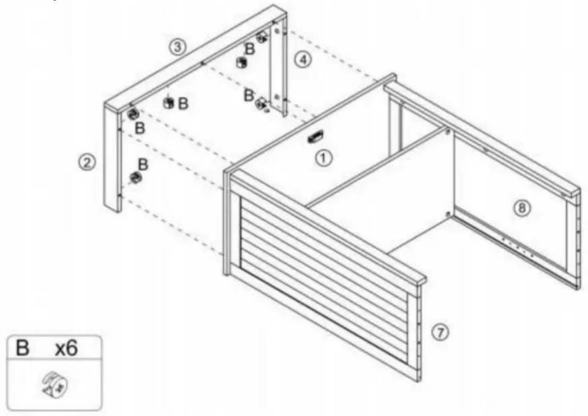
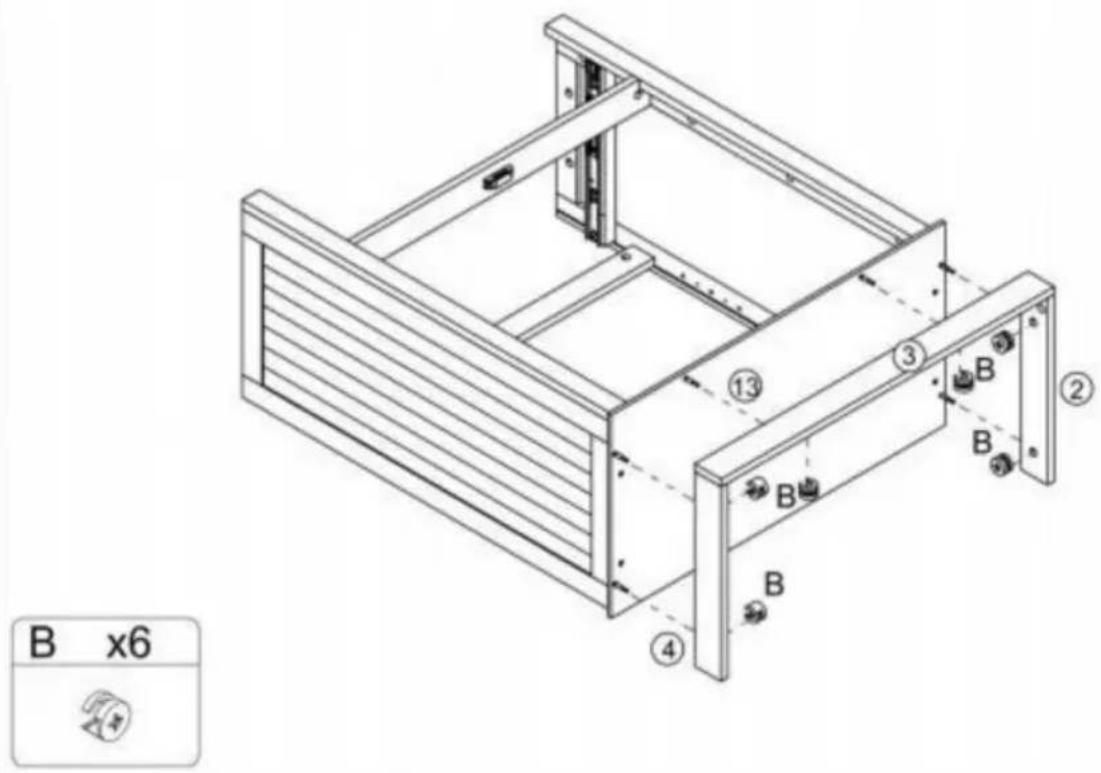
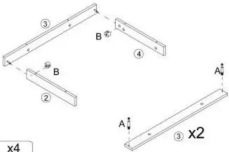
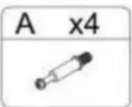
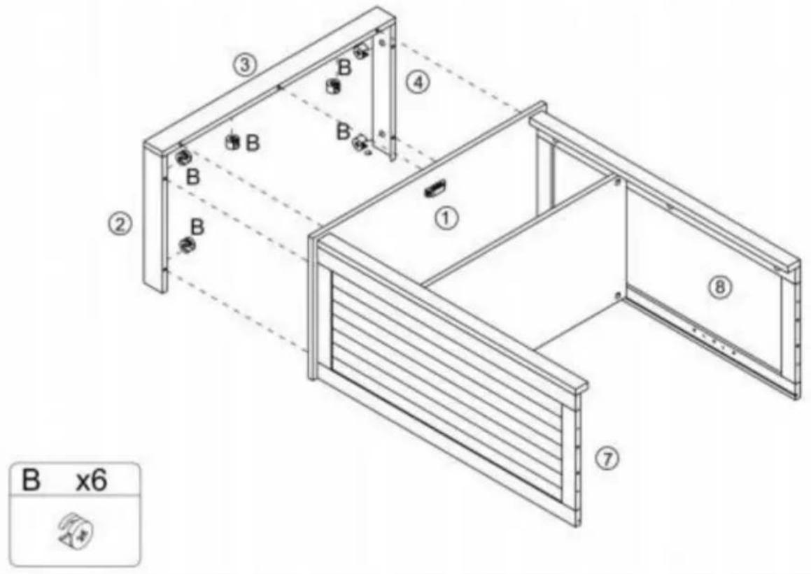
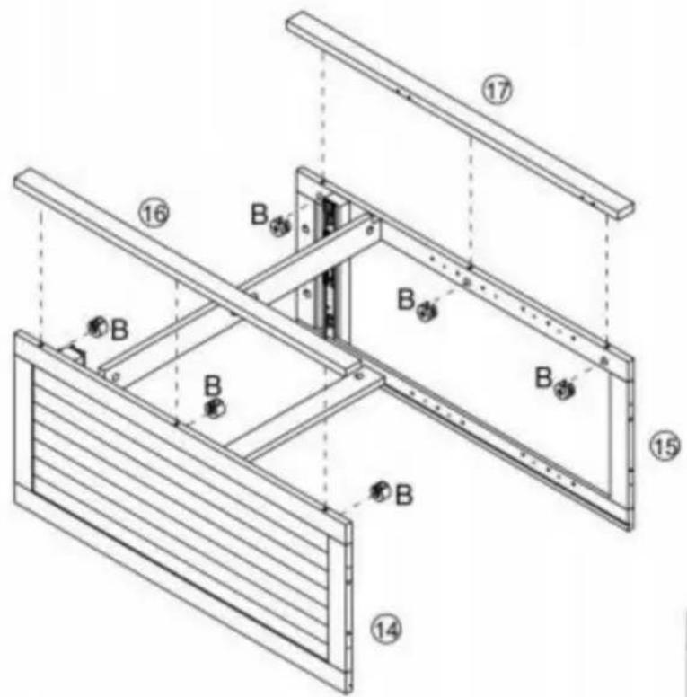
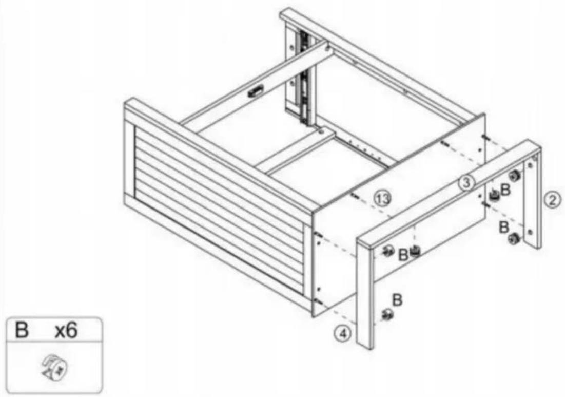
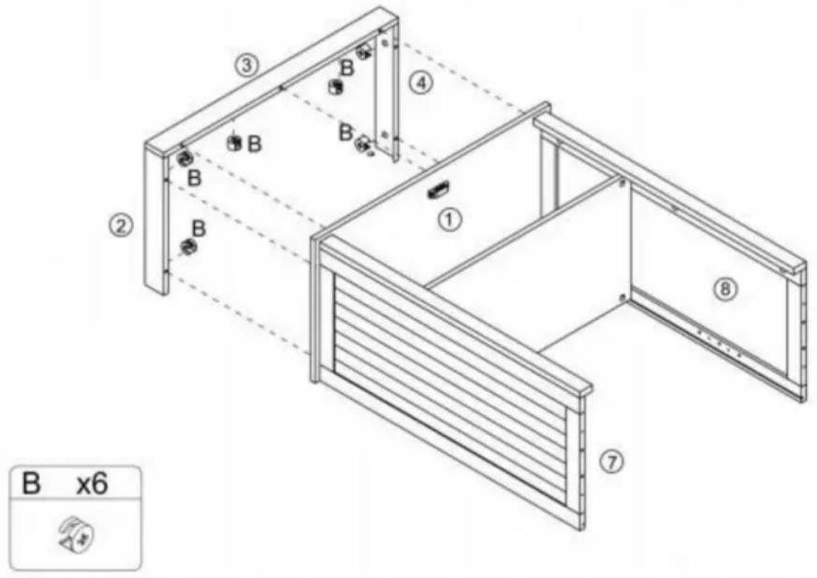
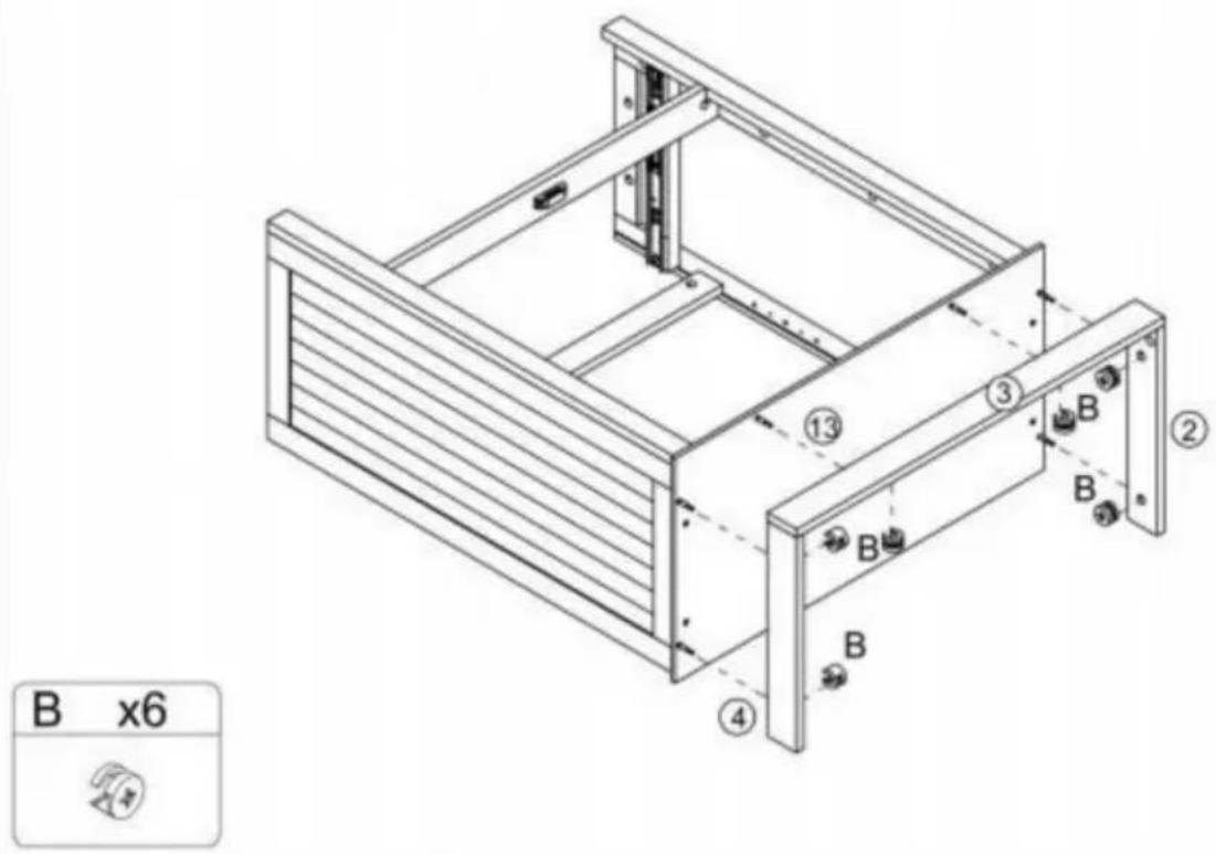
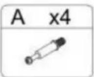
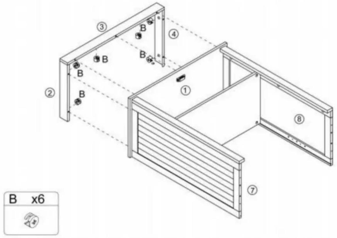
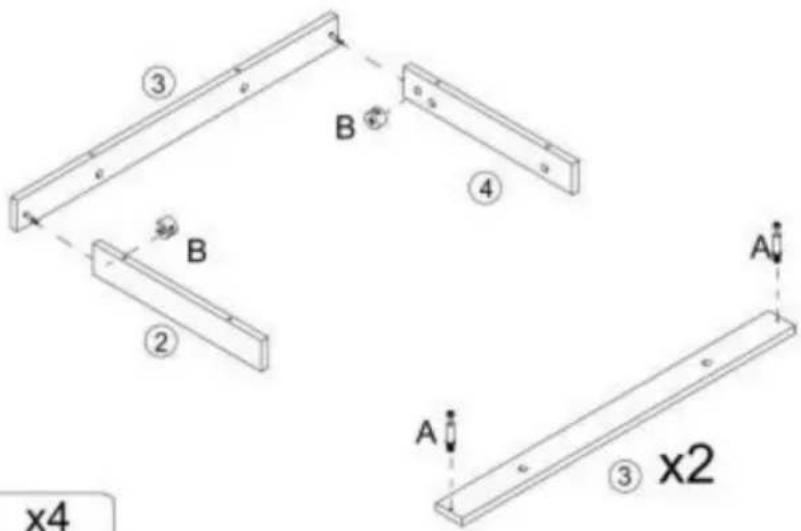
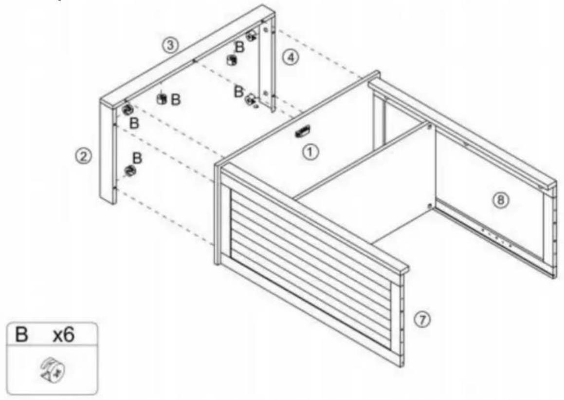
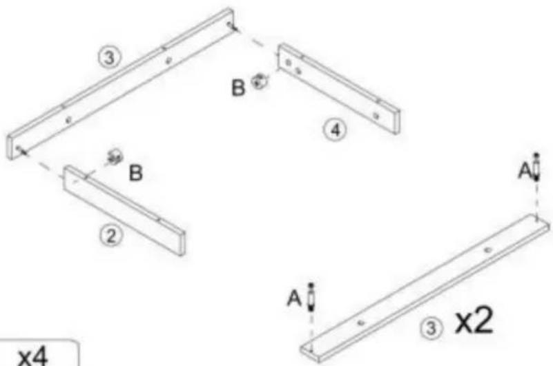
③ B ④ B ② A ③ x2 B x4 A x4Step 6
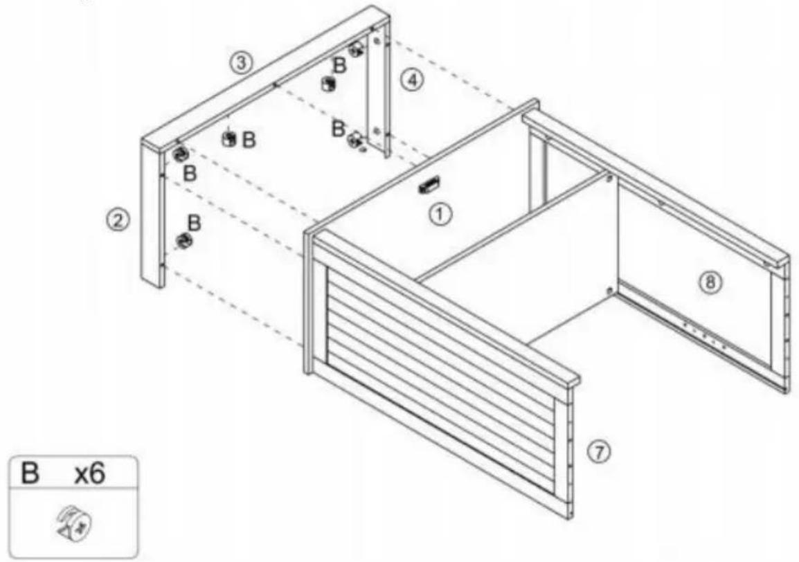
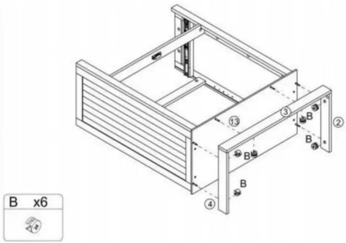
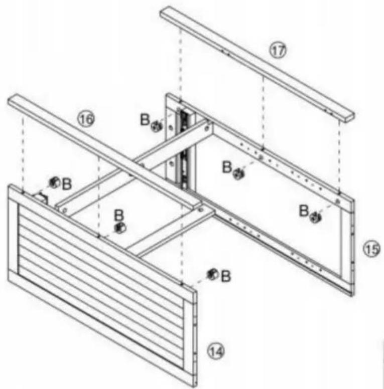
text_image
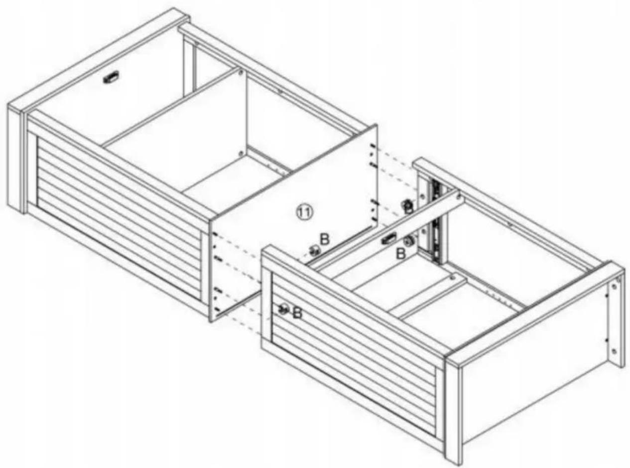
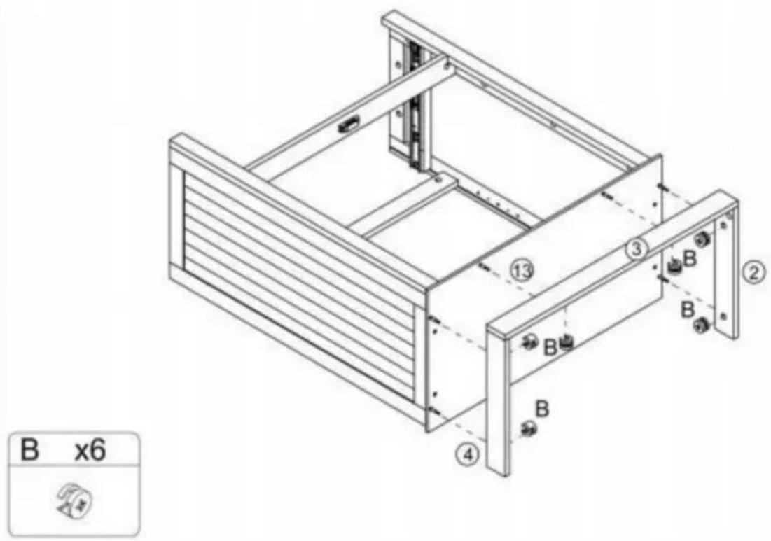
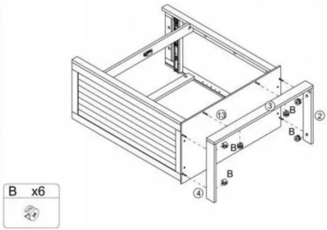
B x6Step 7
text_image
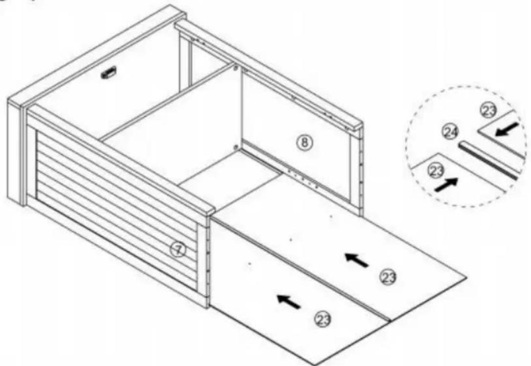
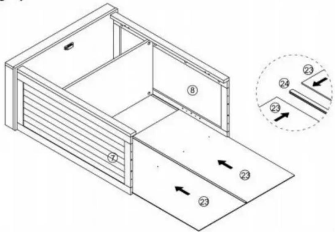
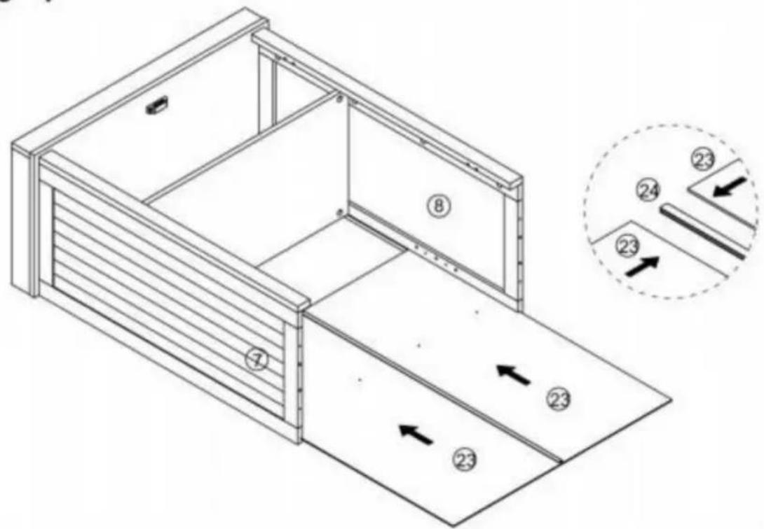
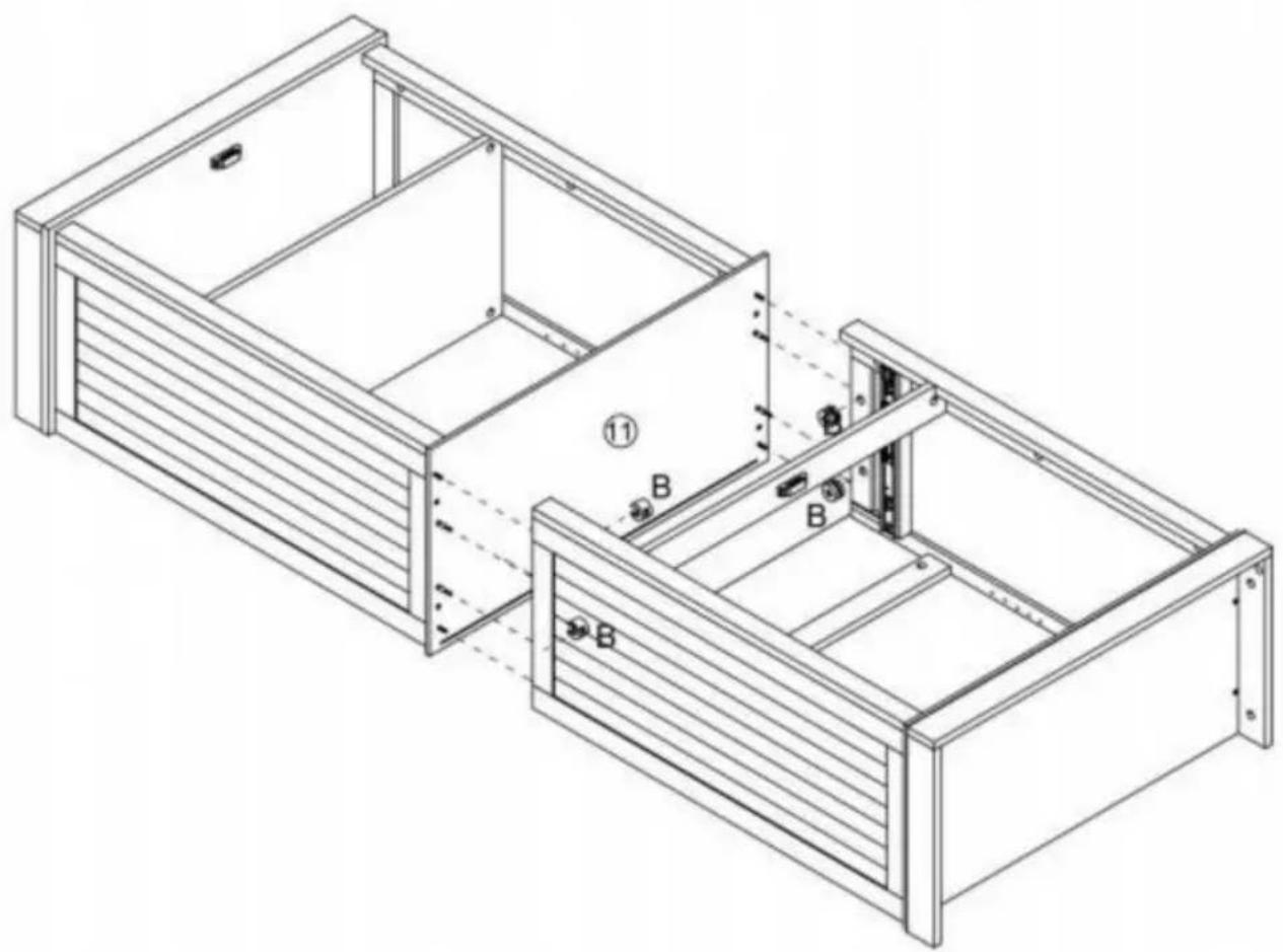
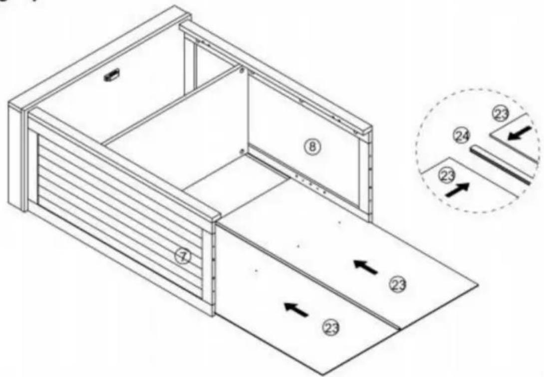
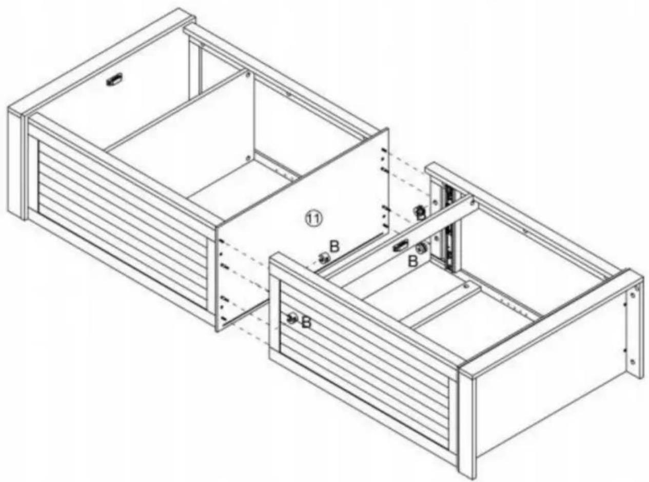
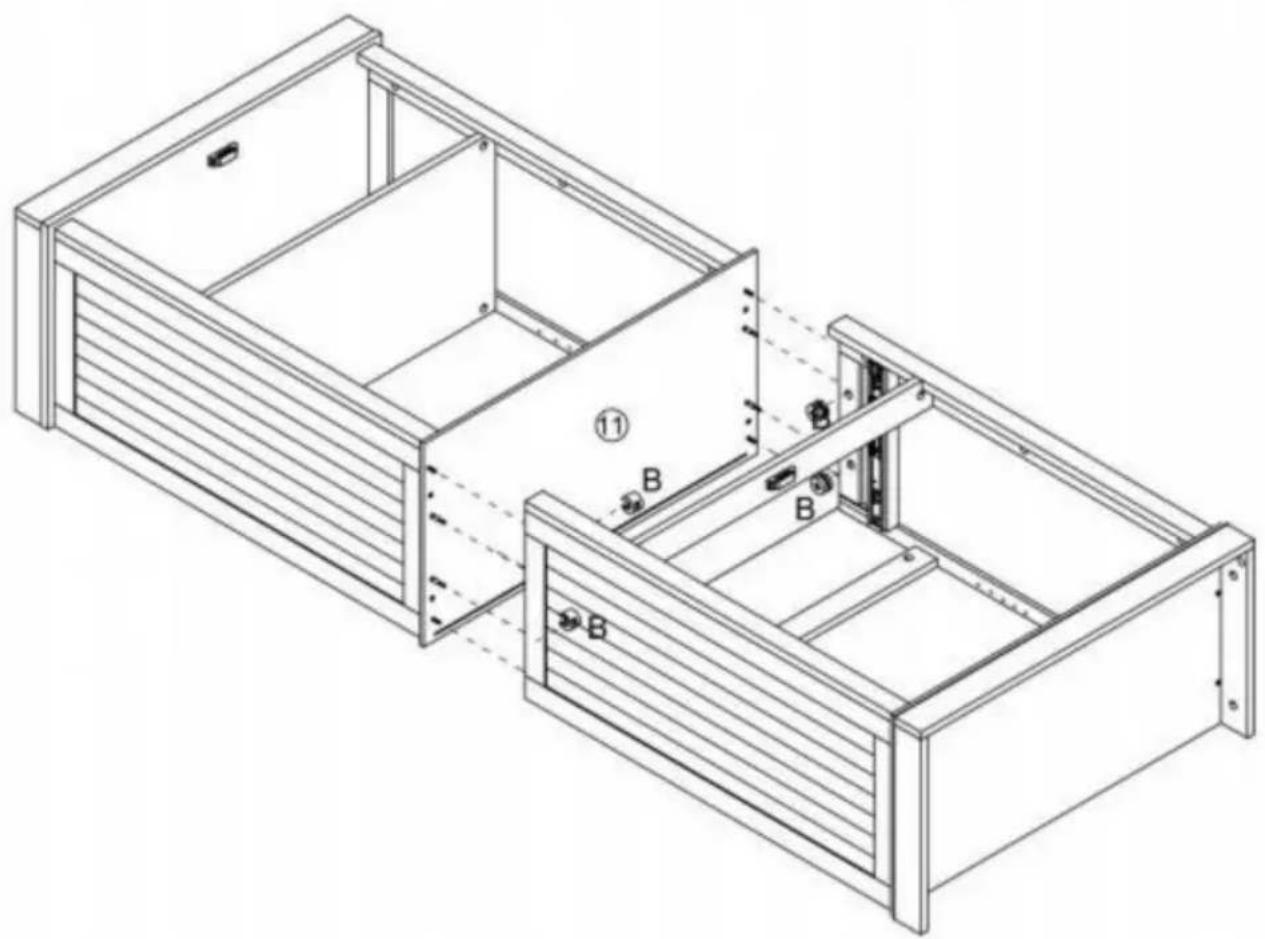
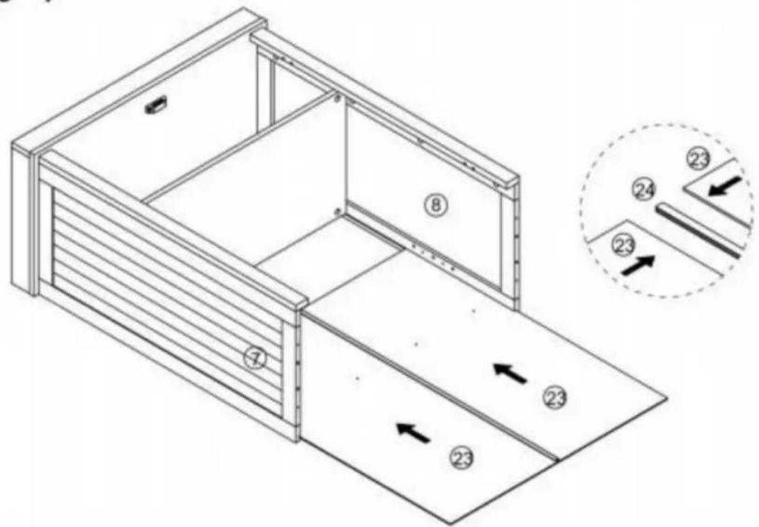
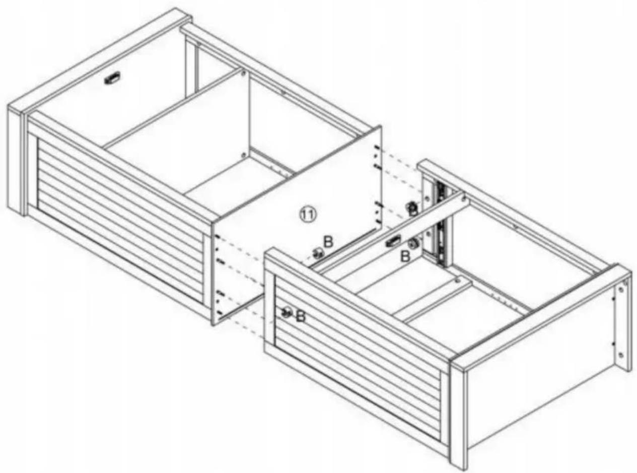
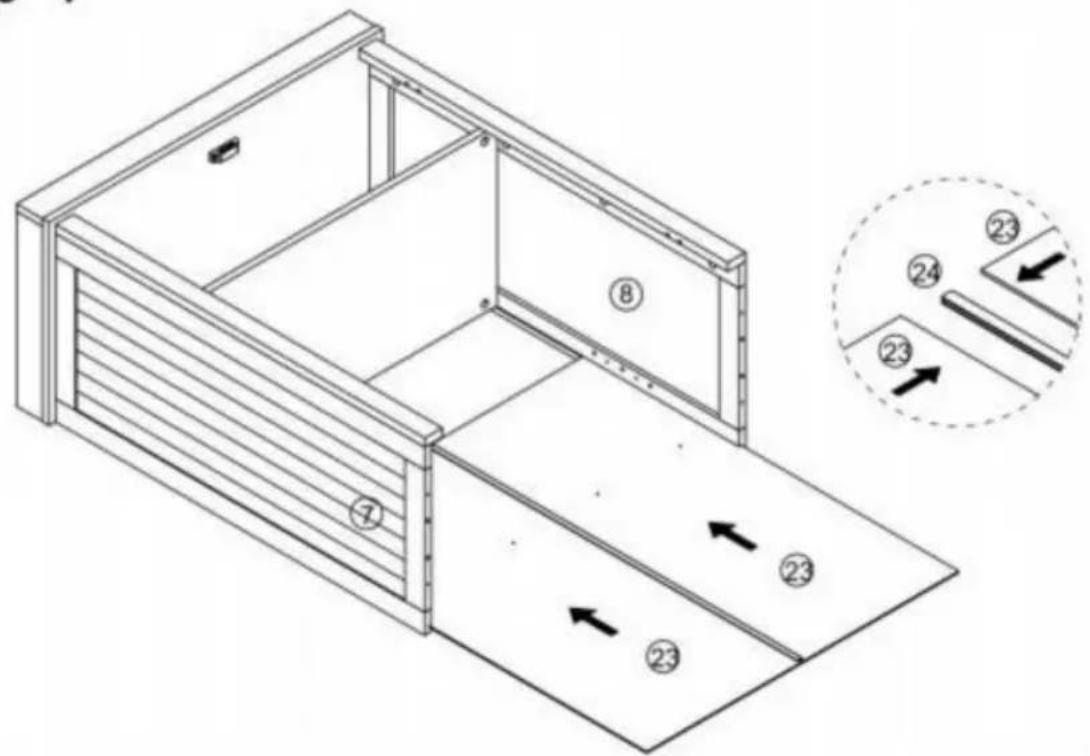
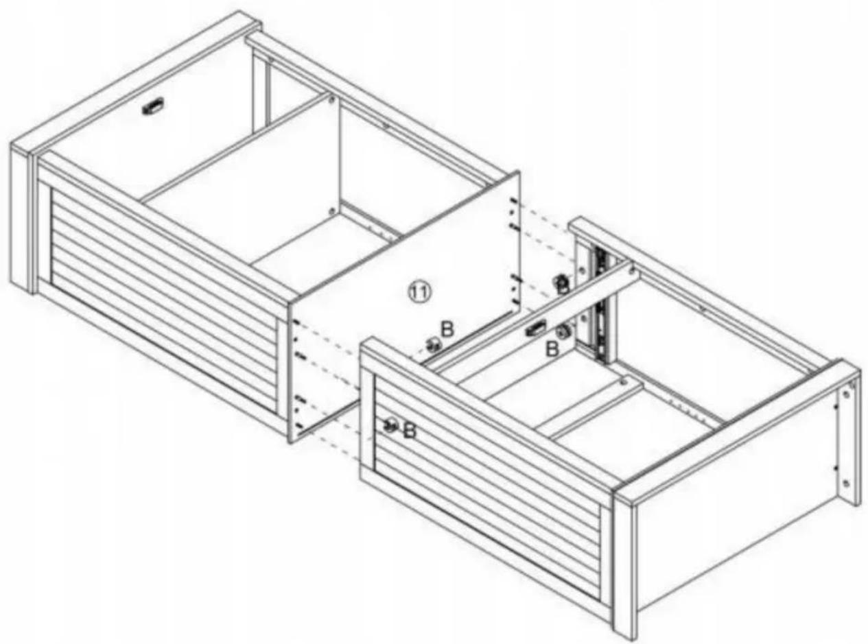
Technical diagram of a modular drawer with numbered components and directional arrows indicating movement or flow.Step 8
text_image
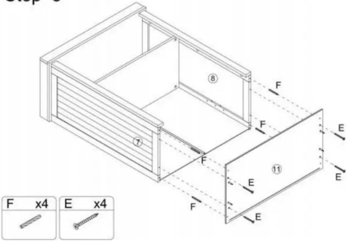
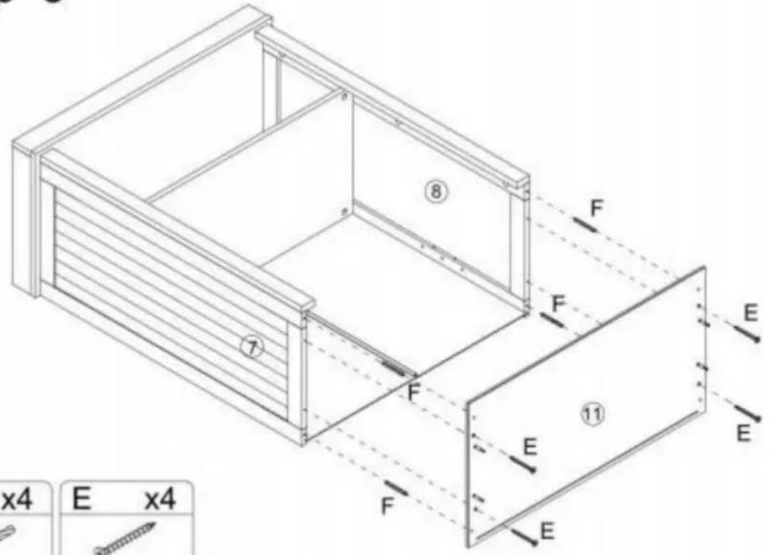
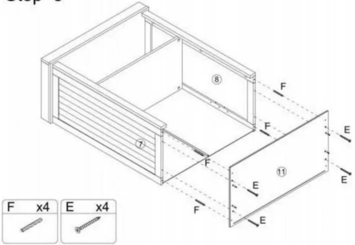
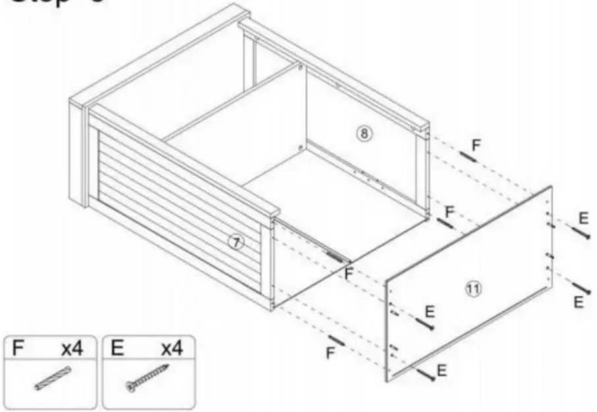
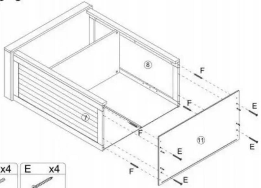
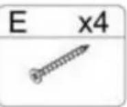
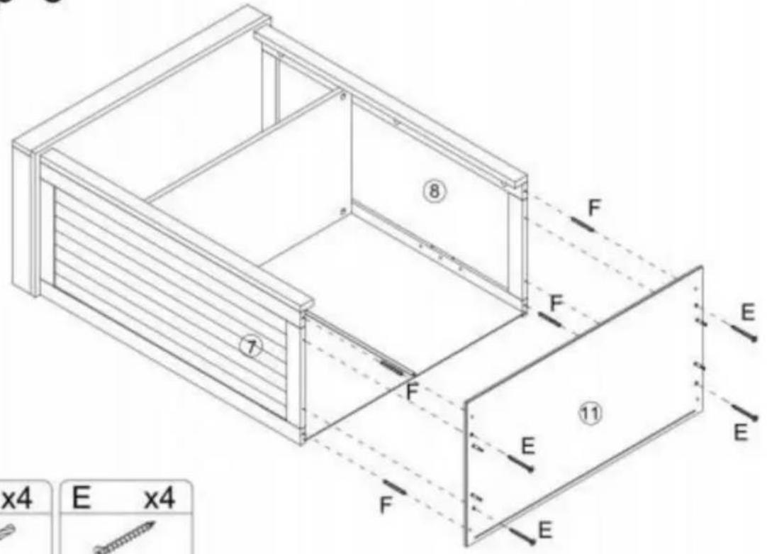
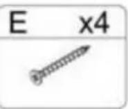
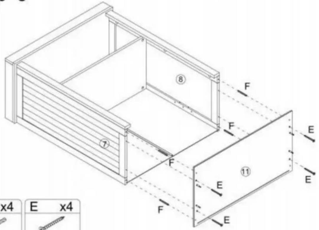
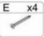
Step 5 F x4 E x4 ⑧ ⑦ F F E ⑪ E E F F E ②Step 9
text_image
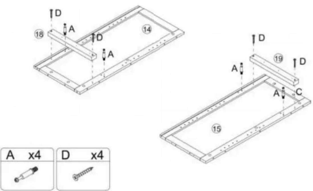
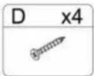
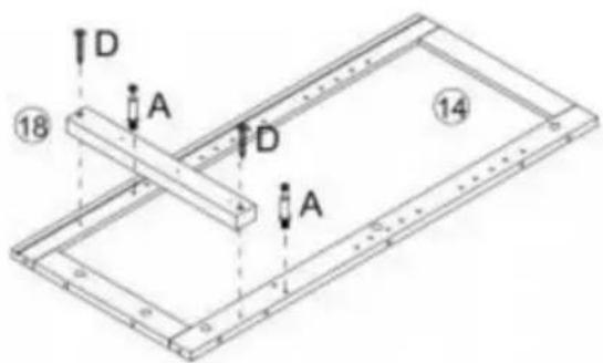
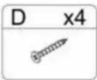
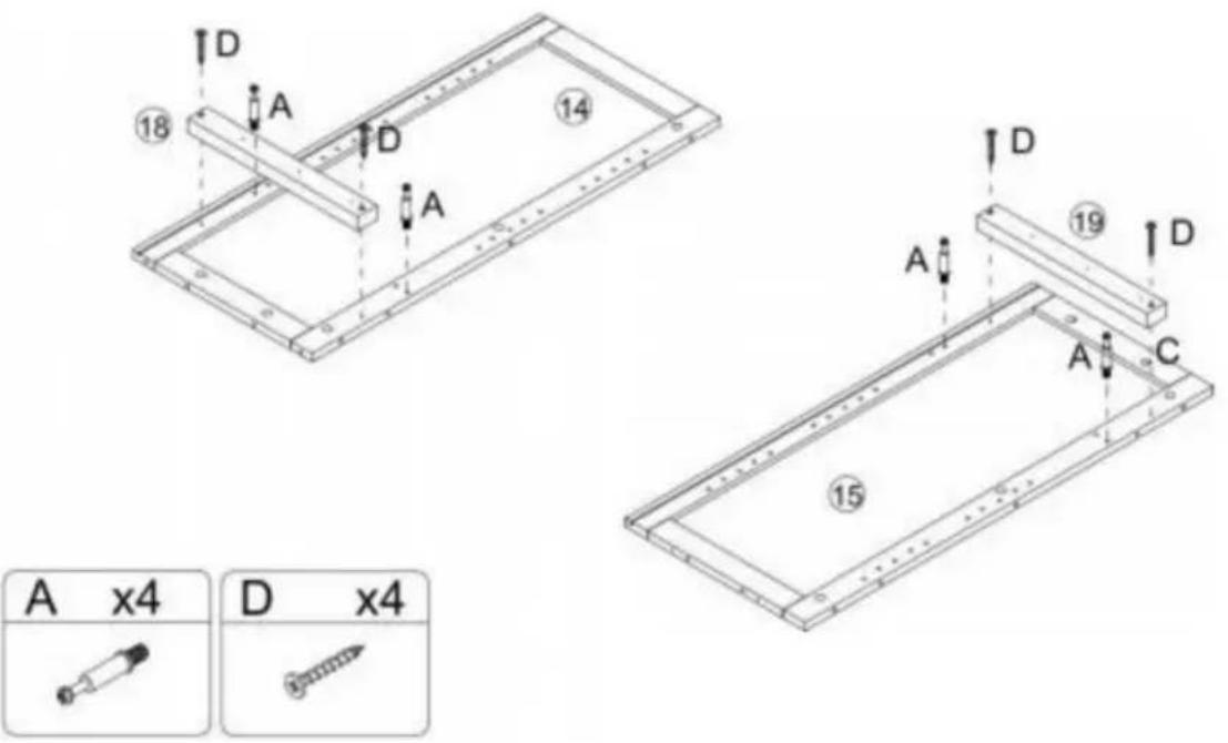
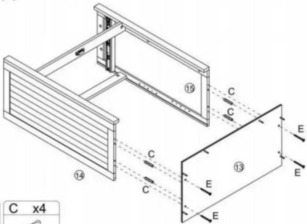
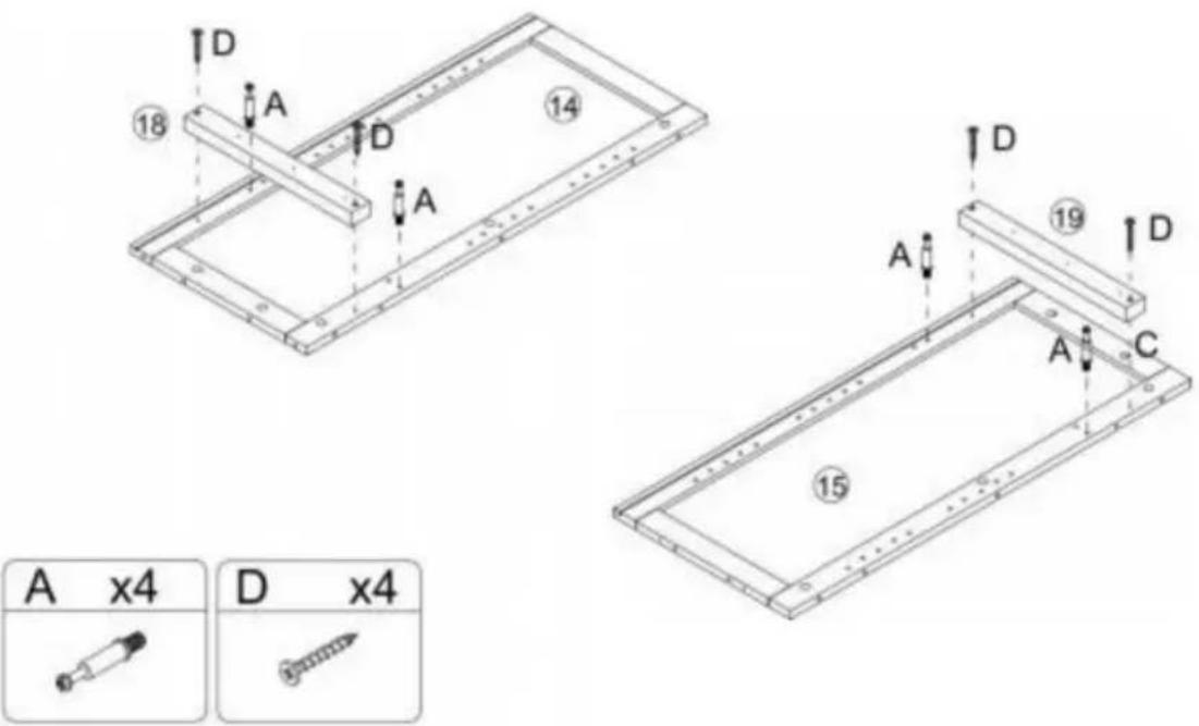
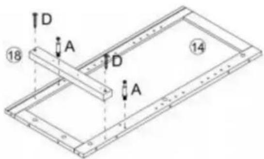
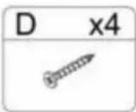
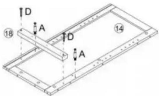
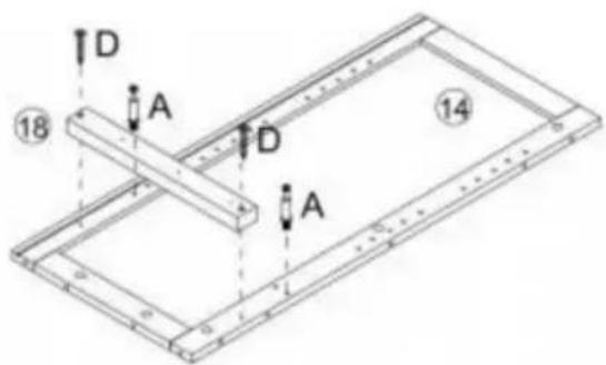
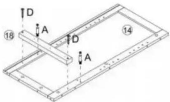
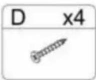
D 18 A D 14 A D 19 A C 15 A x4 D x4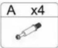
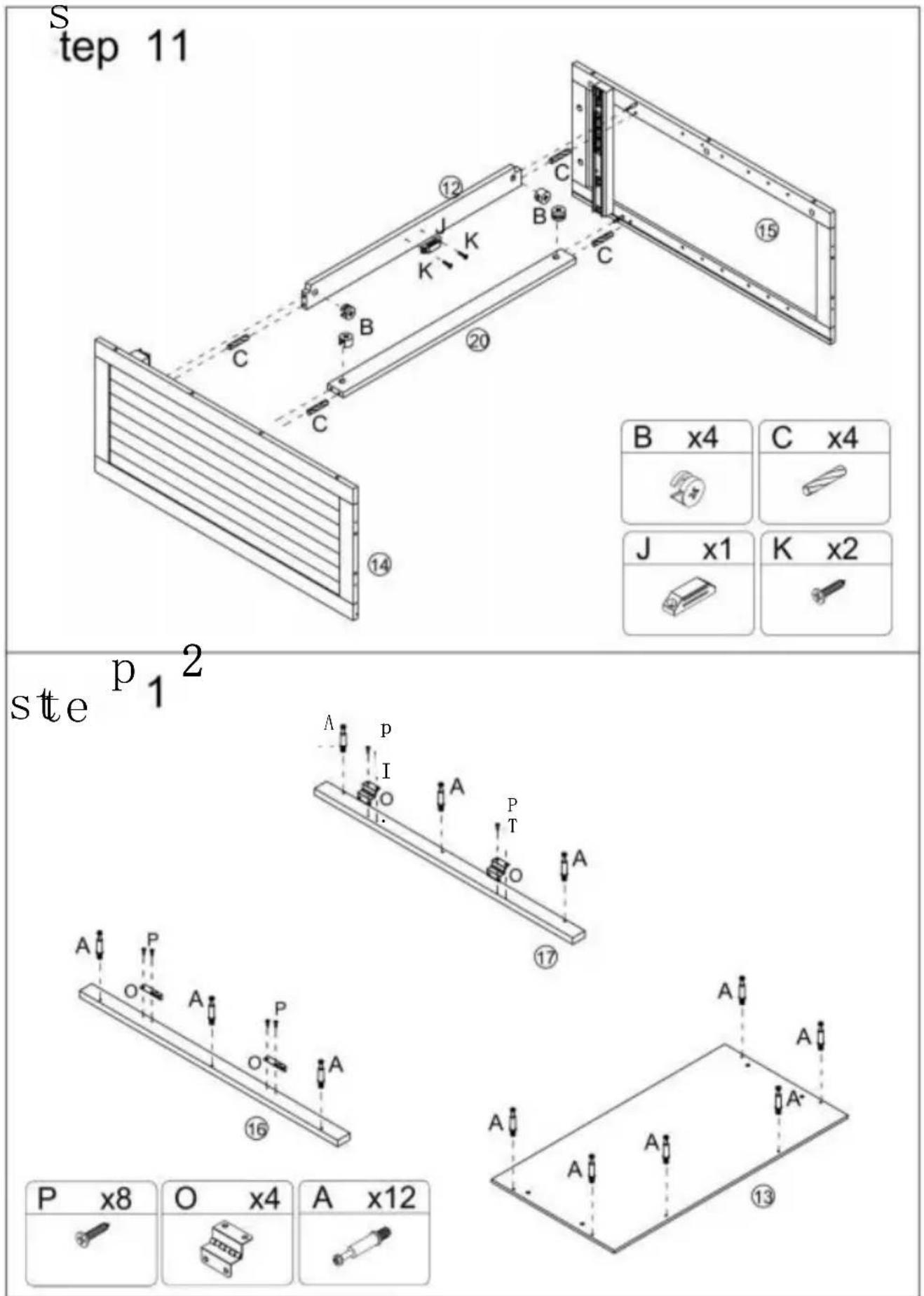
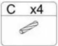
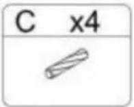
B x4 | C x4 |
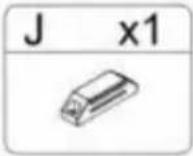
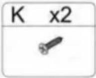
| J x1 | K x2 |
J x1 | K x2 |
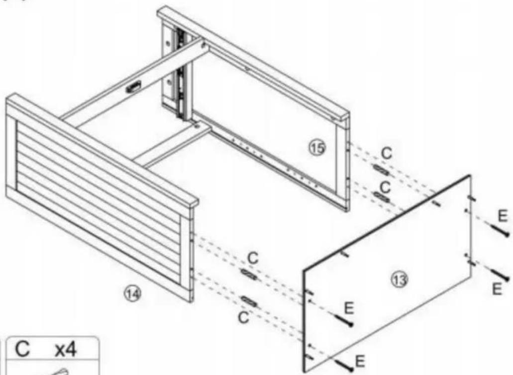
Step 13
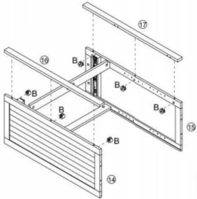
text_image
Technical diagram of a structural frame assembly with numbered components and labeled parts B and h
Step 14
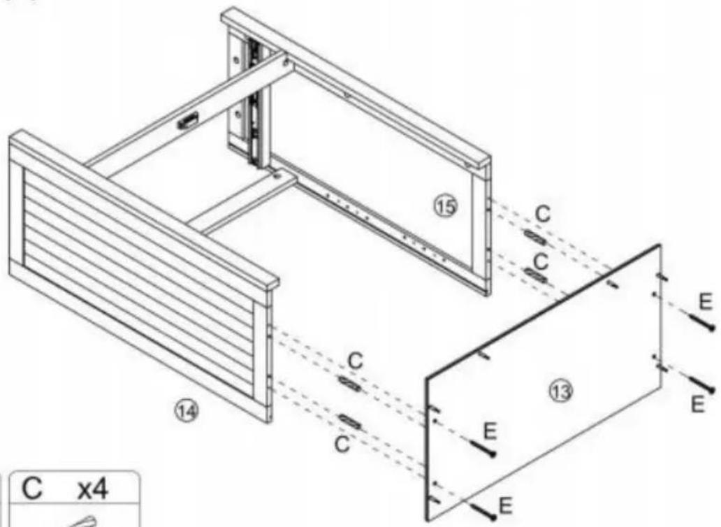
text_image
C x4 ⑭ ⑮ ⑯ ⑰ ⑱ ⑲ ⑳ ⑴ C C C C E E E
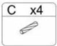
Step 15
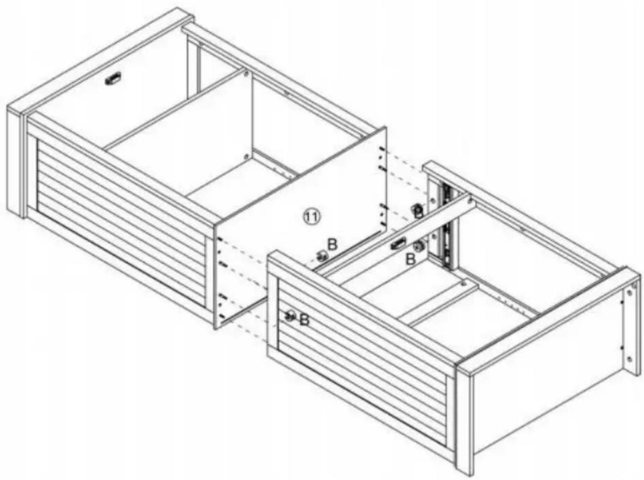
text_image
Technical diagram of a mechanical device with numbered components and directional arrows indicating assembly or assembly steps.Step 17
natural_image
Isometric line drawing of a two-compartment electronic device with internal components and mounting holes (no text or symbols)
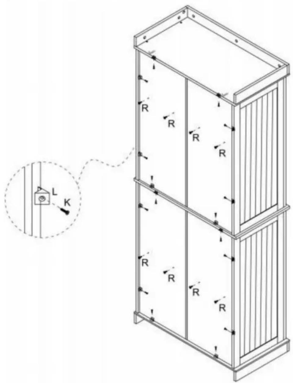
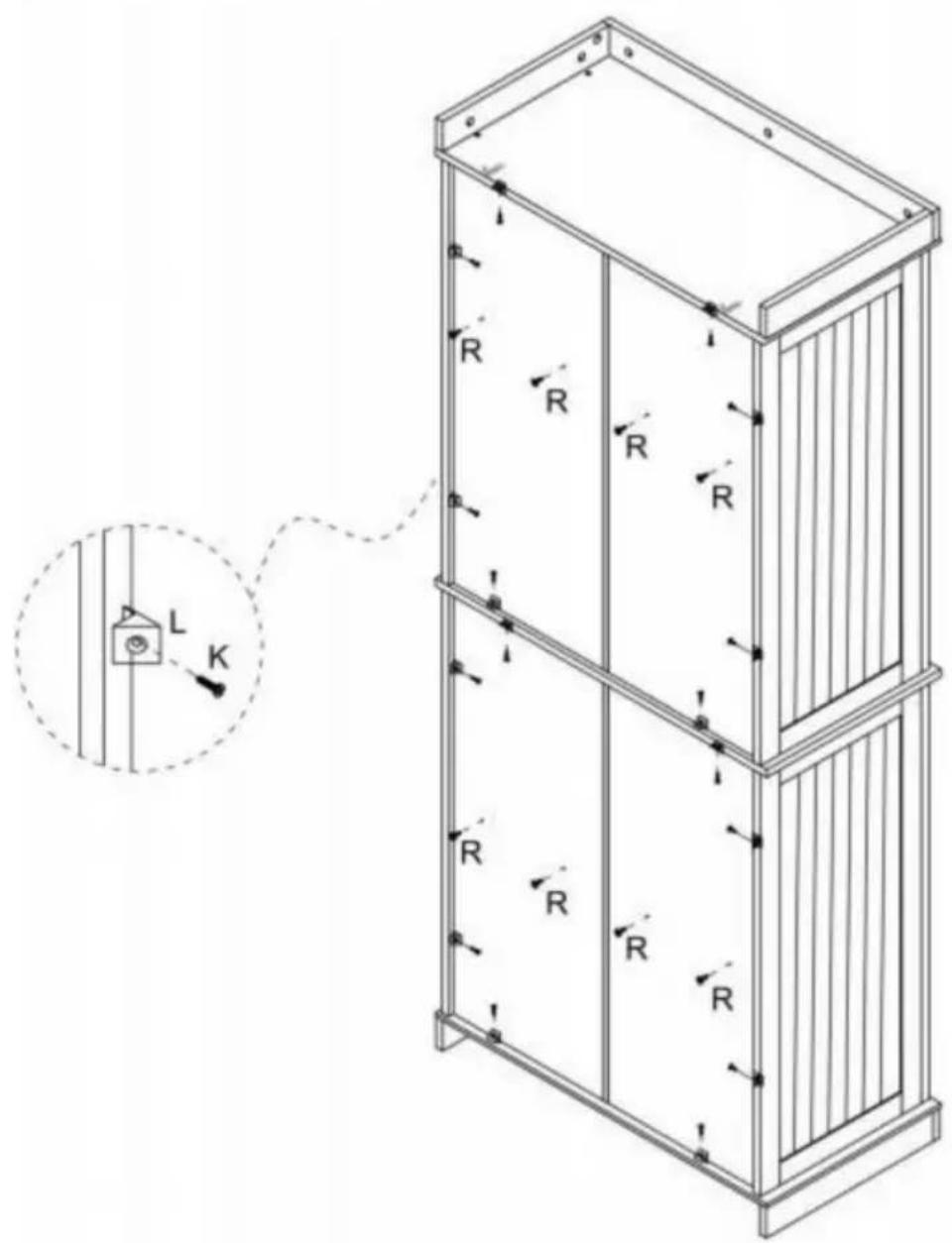
Step 18
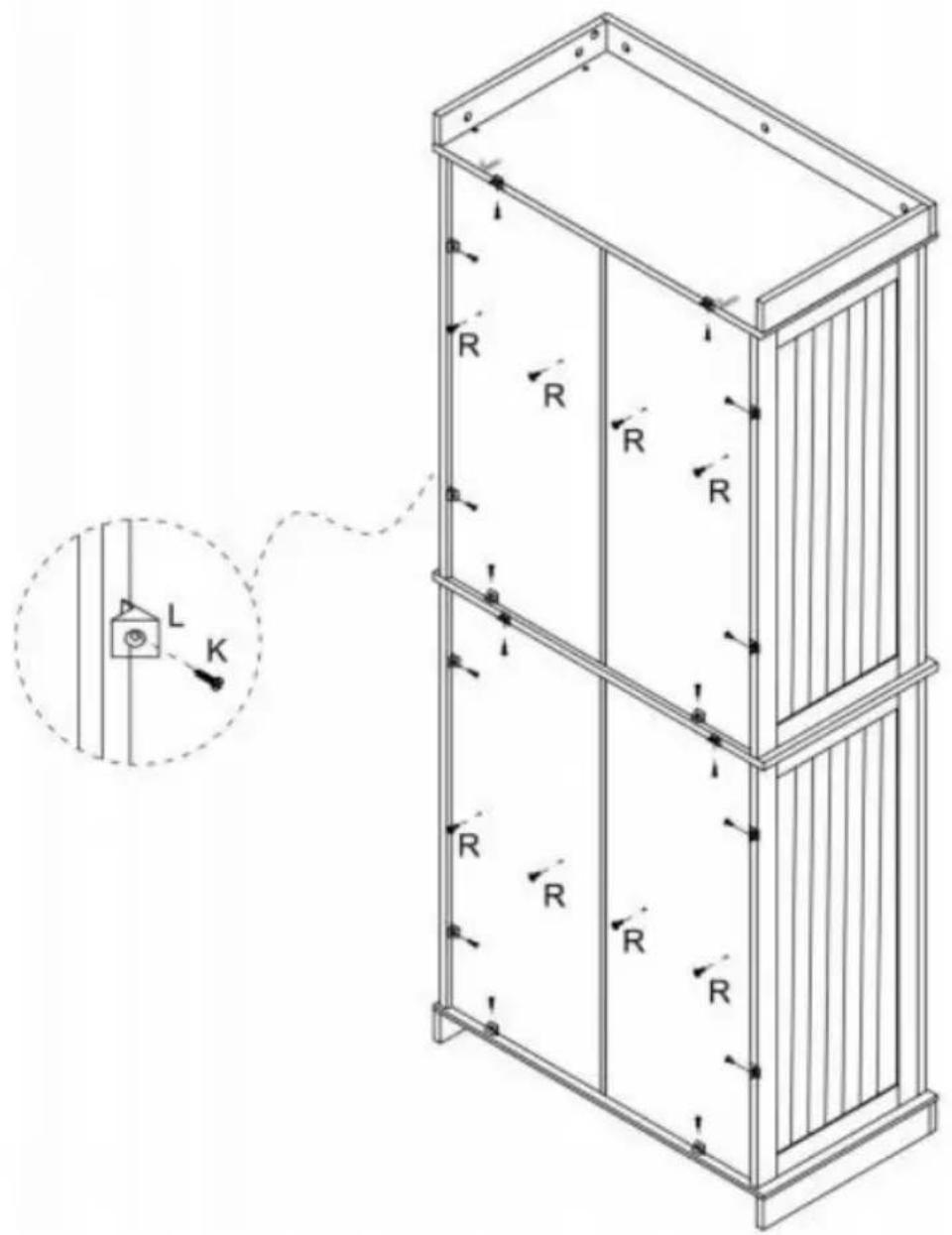
text_image
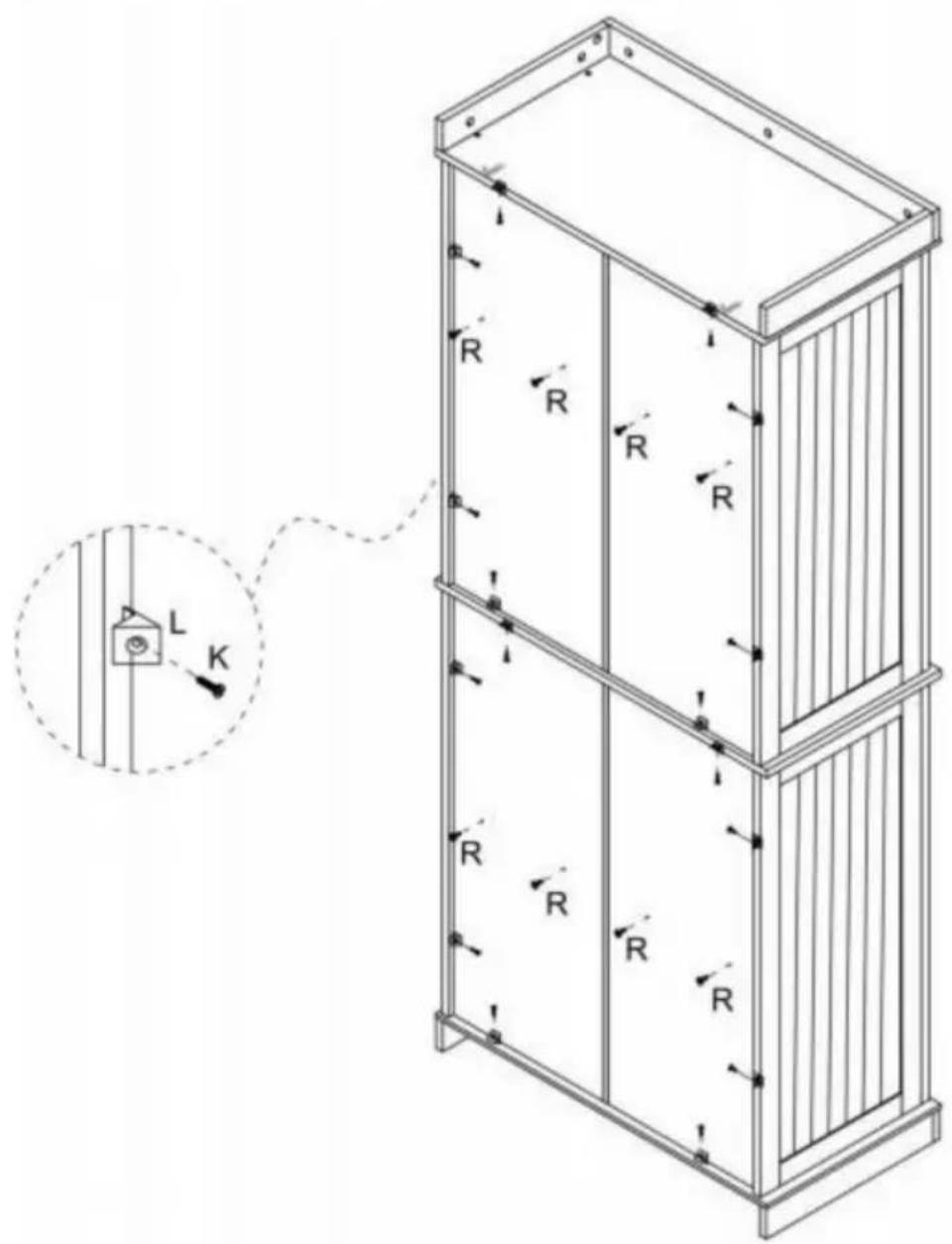
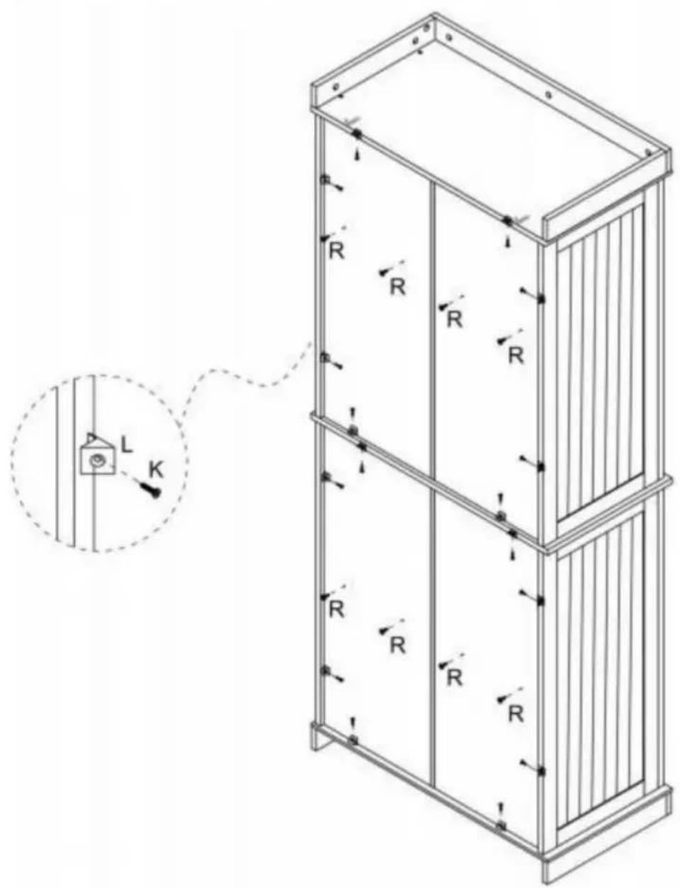
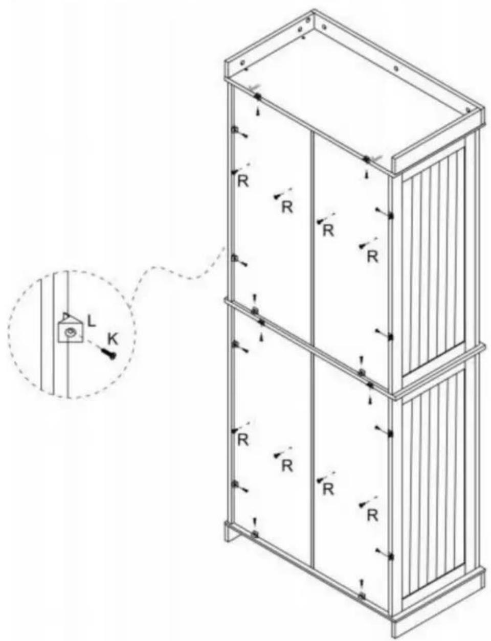
Technical diagram of a multi-level elevator structure with labeled components and directional arrows, including a magnified inset showing a component labeled L and K.K x16] IL\~x16j

1 j
R x8 ]

Step 19
text_image
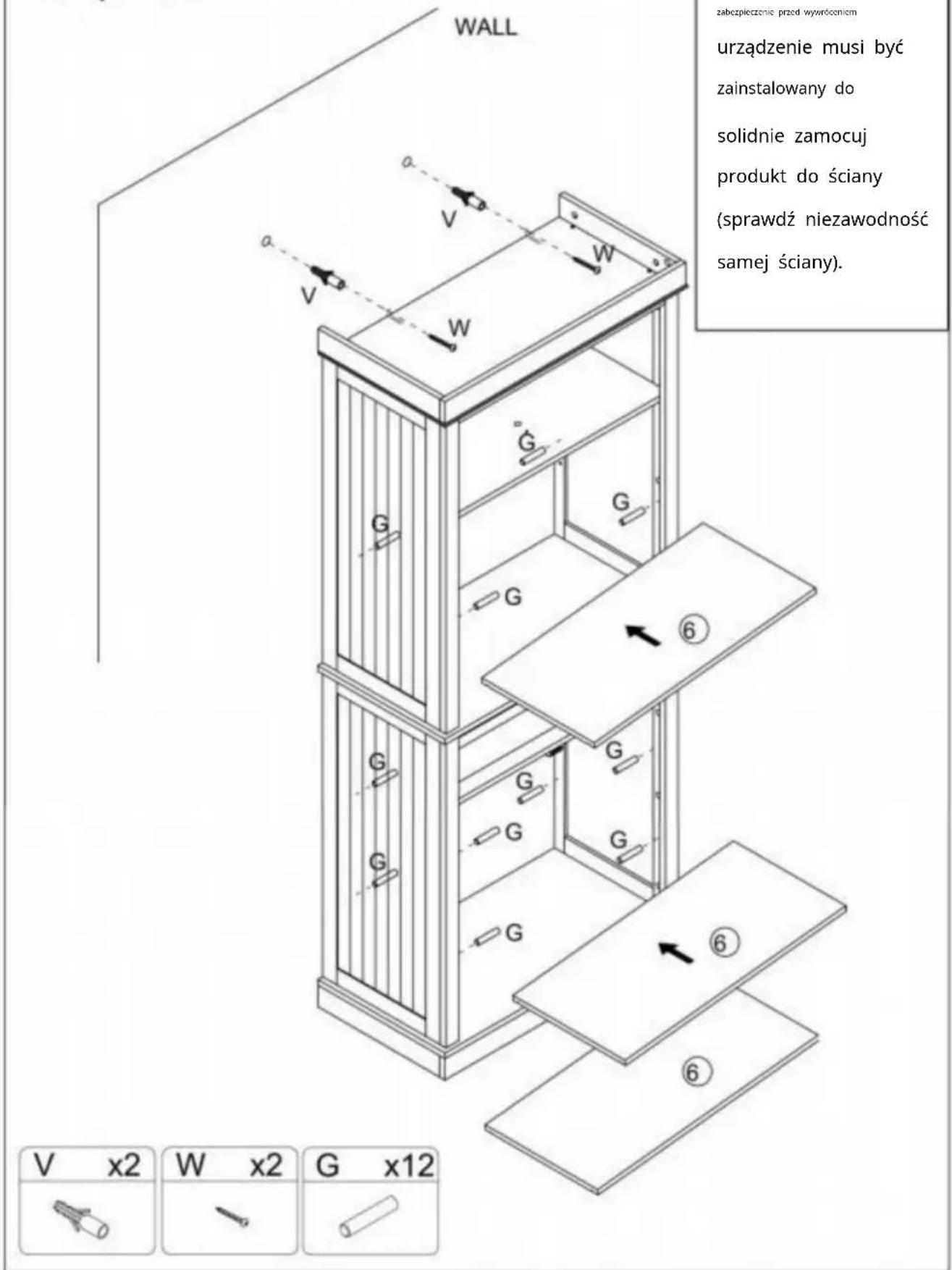
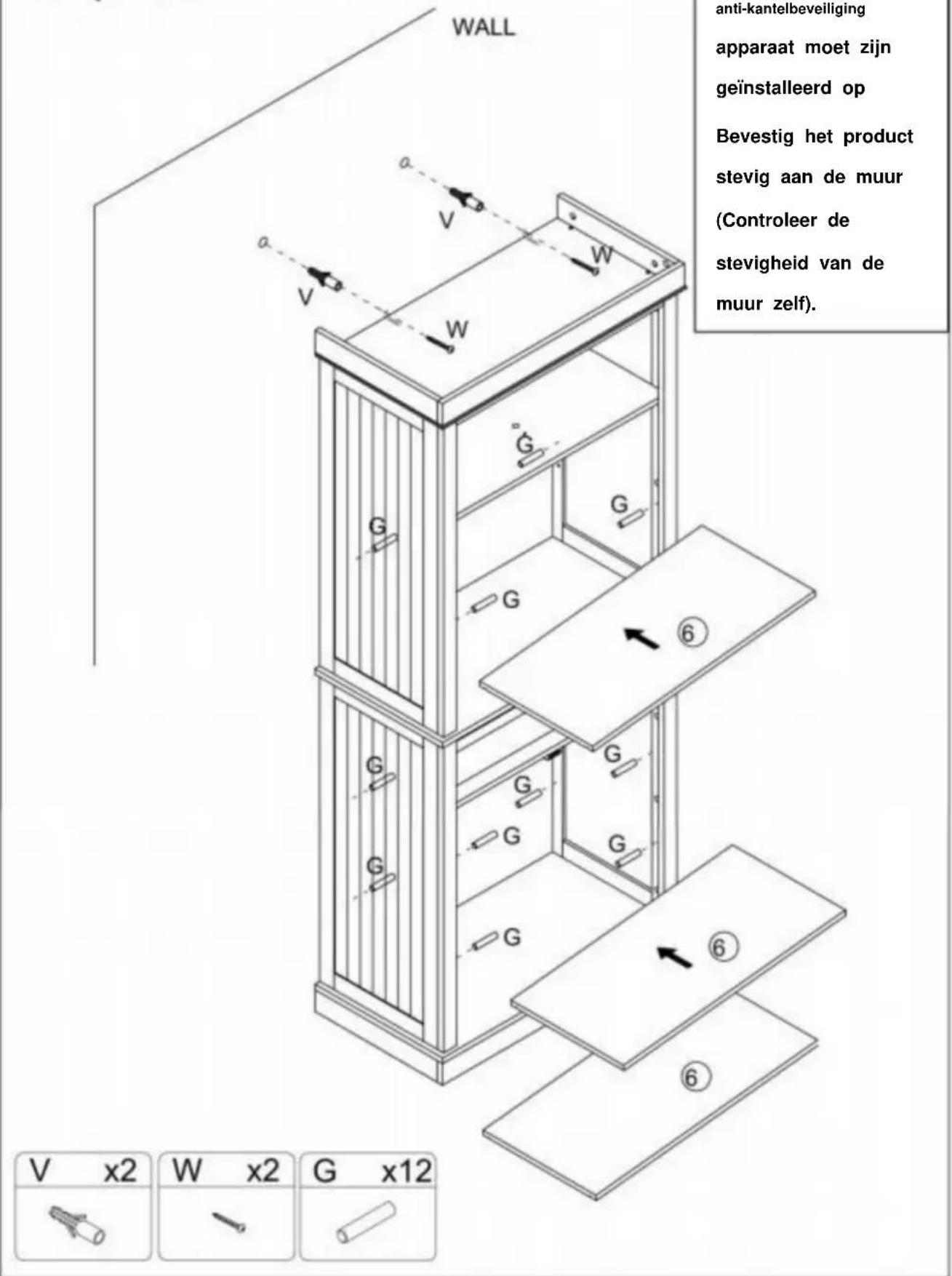
WALL anti tipping device must be installed to securely secure the product to the wall (Ensure the reliability of the wall itself). V x2 W x2 G x12Step 20
text_image
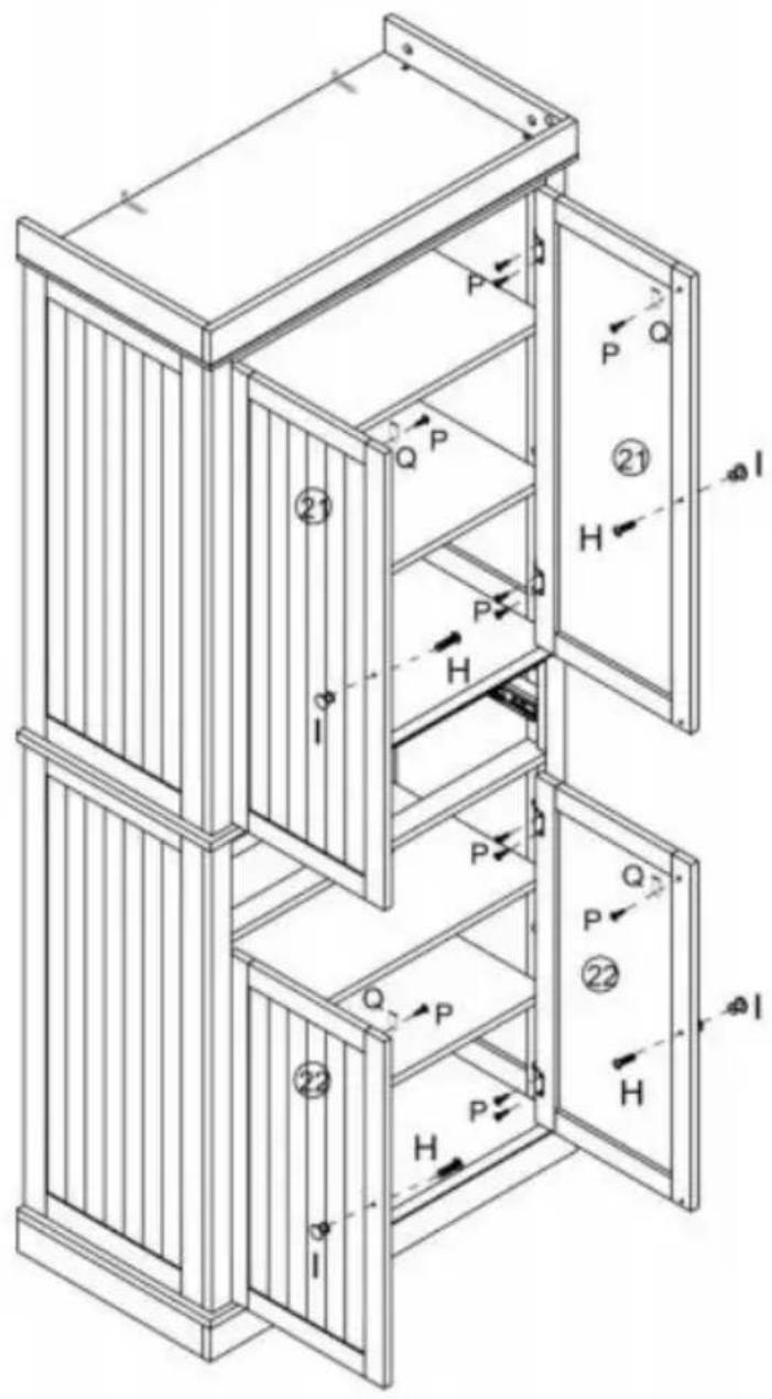
Technical diagram of a multi-level cabinet with labeled components and directional arrows indicating flow or movement.IH 1x4]
p x4l
rp\~x2oi [Q^4]
1 9 1

Step 21
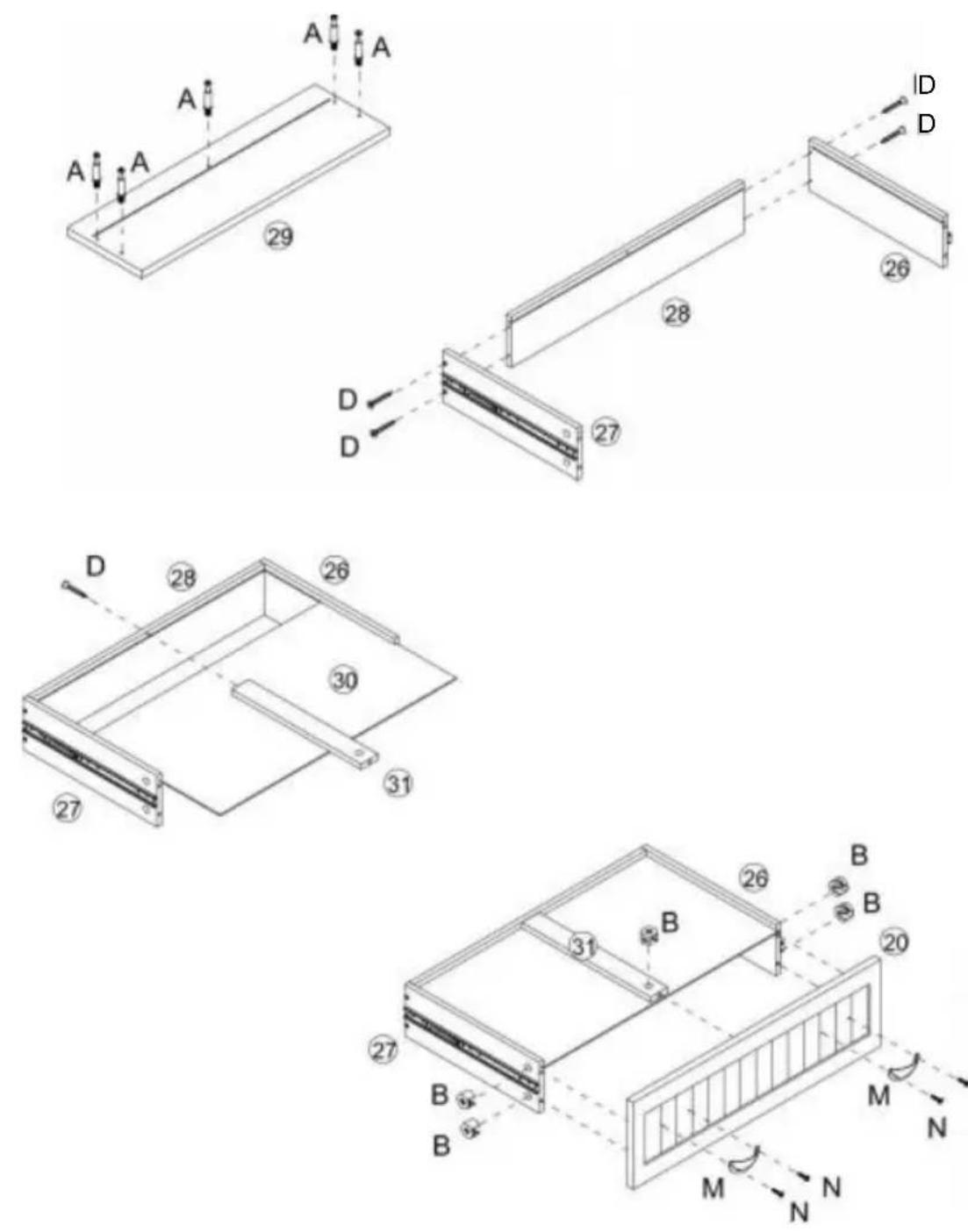
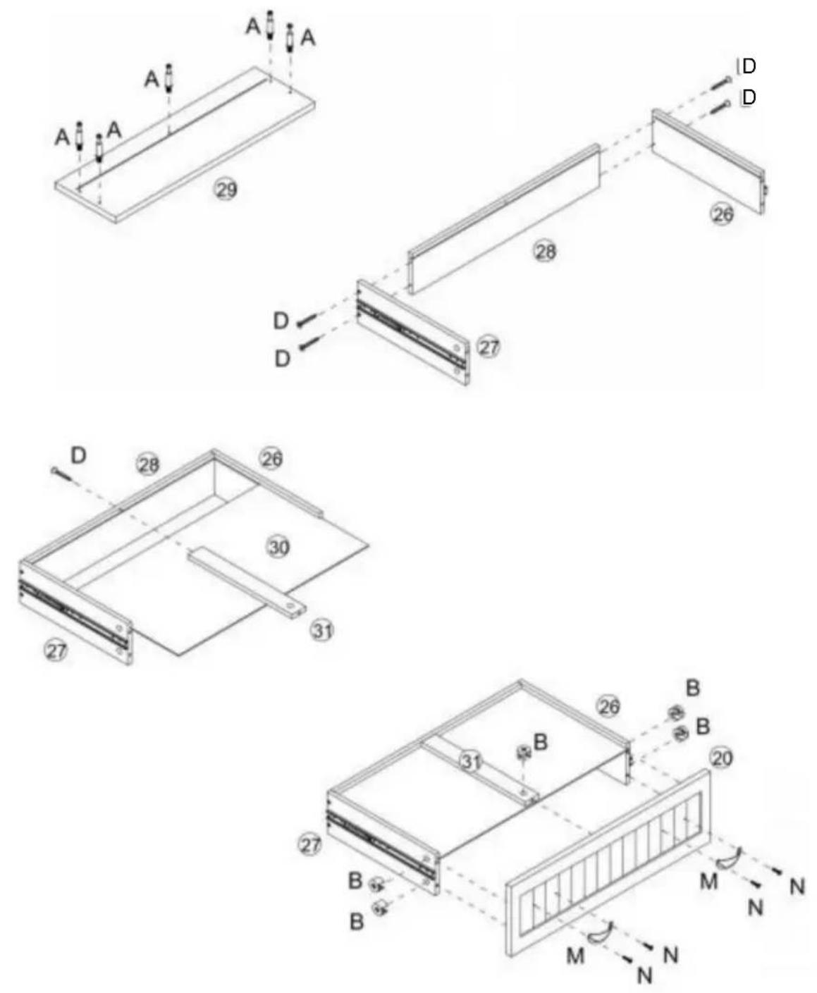
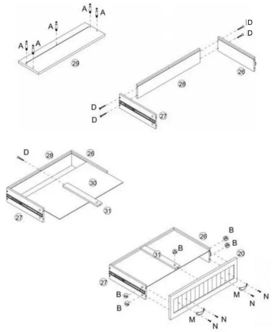
| A x5 | D x5 | B x5 | M x2 | N x4 |
 |  |  |  |  |
Step 22
natural_image
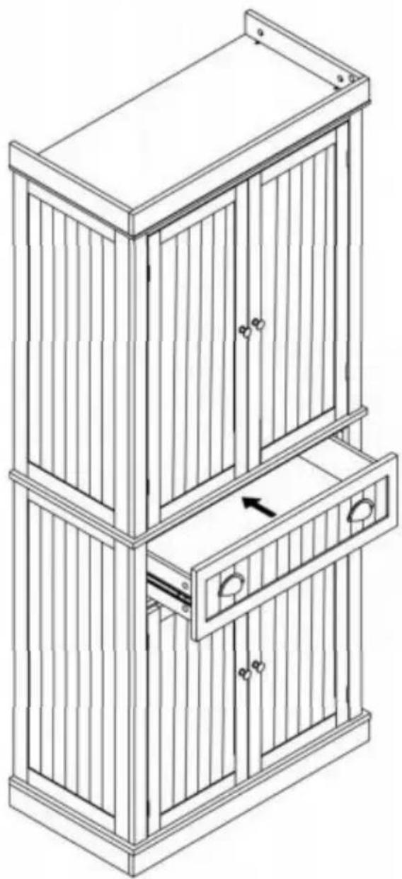
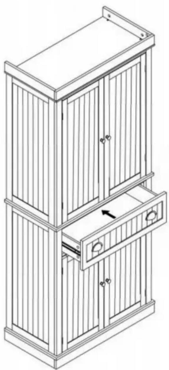
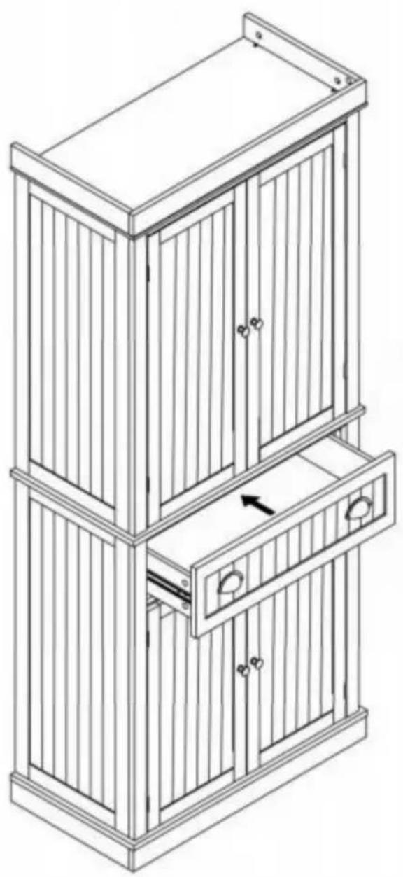
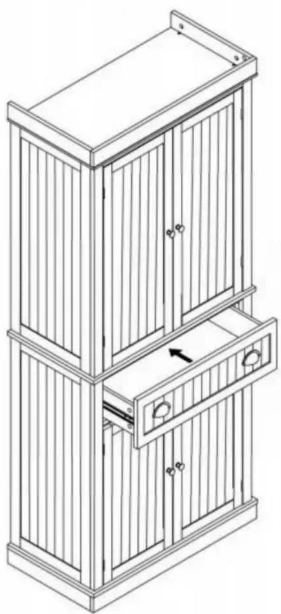
Line drawing of a multi-level wooden cabinet with drawers and doors, no text or symbols present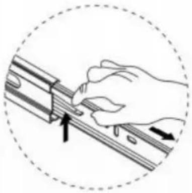
natural_image
Illustration of a hand using a tool to adjust or install a mechanical component, enclosed in a dashed circle (no text or symbols)Pay attention to hand injuries caused by drawer pinching!
CLEANING AND STORAGE
- Wipe with a soft, dry cloth. Never use an abrasive cleanser or harsh pad. Do not clean with water or other liquids.
- Be sure to keep the product dry
- Children are not allowed to wipe the product to avoid tipping and falling injuries.
- Regularly adding industrial grease to the door spindle and drawer slide can reduce noise and extend service life.
TIPS:
- Adding PVC pads for easy cleaning.
VEVOR®
TOUGH TOOLS, HALF PRICE
Technical Support and E-Warranty Certificate
www.vevor.com/support
V ETV LER ^®
MCO, HALF P RIZH ÀTOUG
natural_image
Line drawing of a two-tiered cabinet with doors and drawers (no text or symbols)BESOIN D'AIDE? CONTACTEZ-NOUS!
PARAMÈTRES DU PRODUIT
text_image
Exploded view diagram of a 30-pin door assembly with numbered components for identification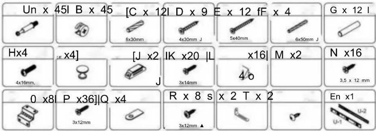
text_image
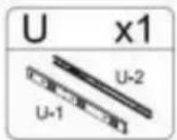
Un x 45I B x 45 [C x 12I D x 9 E x 12 fF x 4 G x 12 I 6x30mm 4x30mm J 5x40mm 6x50mm J Hx4 [J x4] [J x2] IK x20 |L x16| M x2 N x16 4x16mm. J 3x14mm 4 o 3,5 x 12 mm 0 x8 P x36]Q x4 R x 8 s x 2 T x 2 En x1 3x12mm 3x12mm ▲ U-1 U-2
text_image
S x2 T x2 P x8 O x4 A x20Step 2
text_image
Technical diagram of a structural frame with labeled components and dimensions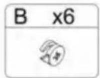
Étape 4
text_image
E E E J K K C C C ① B C C E x4 ⑦ 8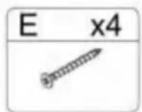
Étape 5
text_image
③ B ④ B ② A A ③ x2 x4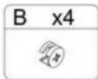
Étape 6
text_image
B x6Step 7
text_image
Technical diagram of a modular drawer with numbered compartments and directional arrows indicating movement or flow.Step 8
text_image
x4 E x4 ⑧ ⑦ F F E ⑪ E E F E x4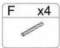
Étape 9
text_image
D A D A ⑱ ⑭ ⑭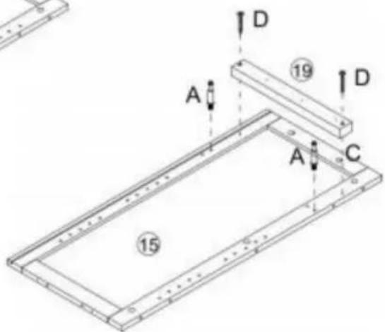
text_image
A D 19 D A C 15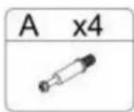
St
p 1 le

natural_image
Illustration of a hand using a tool to adjust or install a mechanical component, with arrows indicating direction (no text or symbols)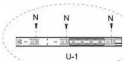
text_image
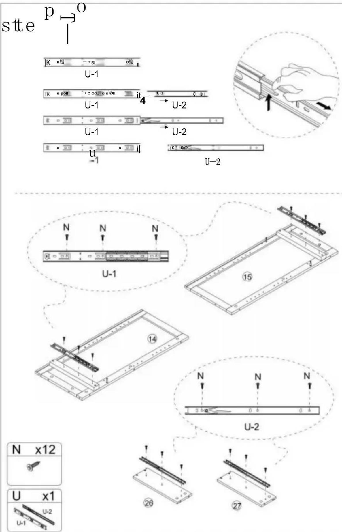
N N N U-1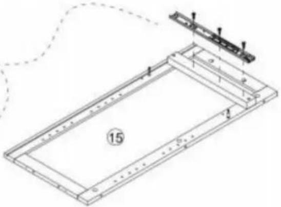
natural_image
Technical line drawing of a rectangular frame with internal components and a small bracket, no text or symbols present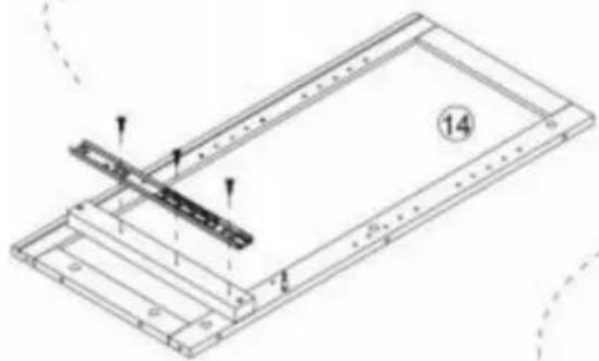
natural_image
Technical line drawing of a mechanical assembly with no visible text or symbols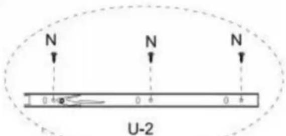
text_image
N N N 0 4 0 4 0 4 U-2
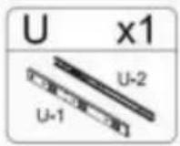
natural_image
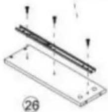
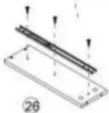
Technical diagram of a mechanical assembly with two parallel strips and mounting holes (no text or symbols)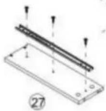
natural_image
Technical diagram of a mechanical assembly with labeled components and arrows indicating motion (no text or symbols present)
Étape 13
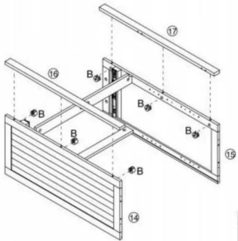
text_image
Technical diagram of a structural frame assembly with numbered components and labeled parts B and flanges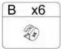
Step 14
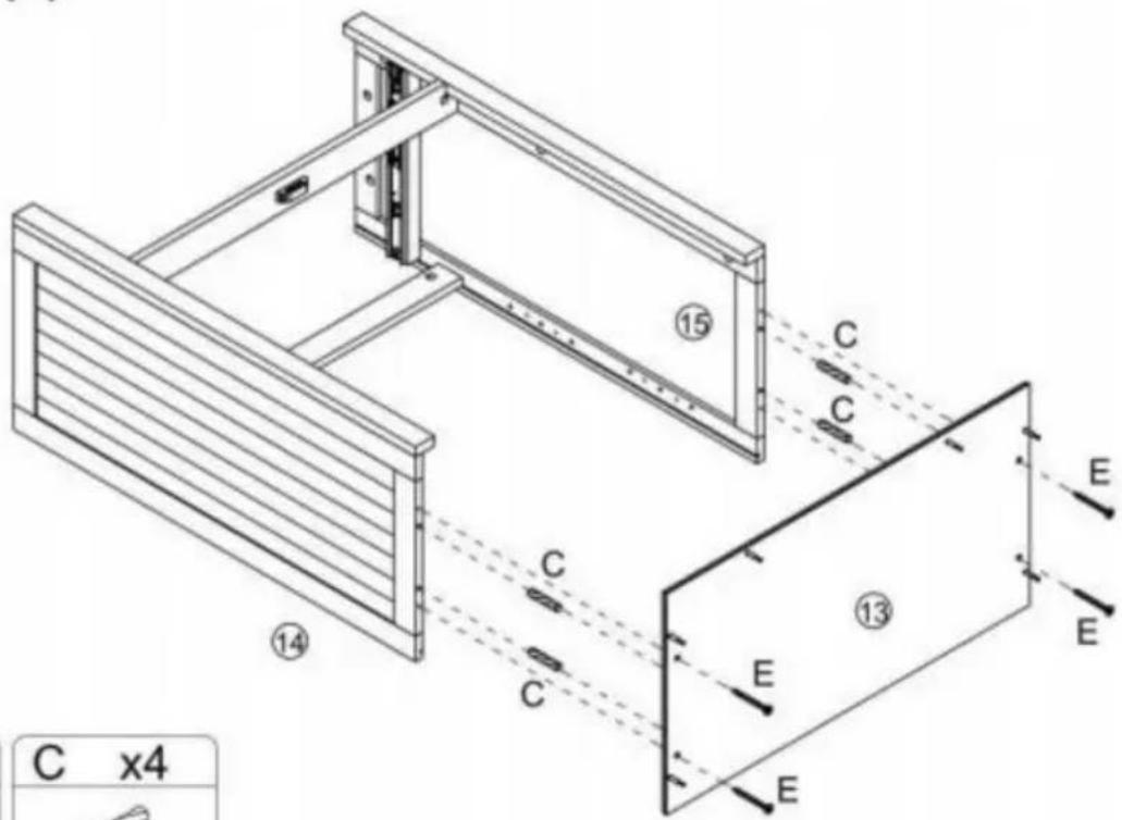
text_image
C x4 ⑭ ⑮ ⑯ ⑰ ⑱ ⑲ ⑳ ⑴ C C C E E E E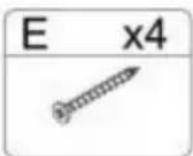
Étape 15
text_image
Technical diagram of a mechanical device with numbered components and directional arrows indicating assembly or movement.Étape 17
natural_image
Isometric line drawing of a two-compartment electronic device with internal components and mounting holes (no text or symbols)
Étape 18
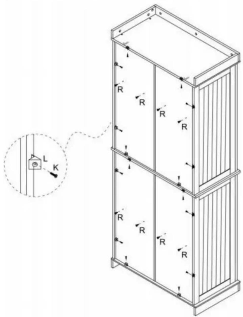
text_image
Technical diagram of a multi-level cabinet with labeled R-R and directional arrows, including an inset showing a switch labeled L and switch K.K x16] IL \~ x16j R x8 ]

1 j

Step 19
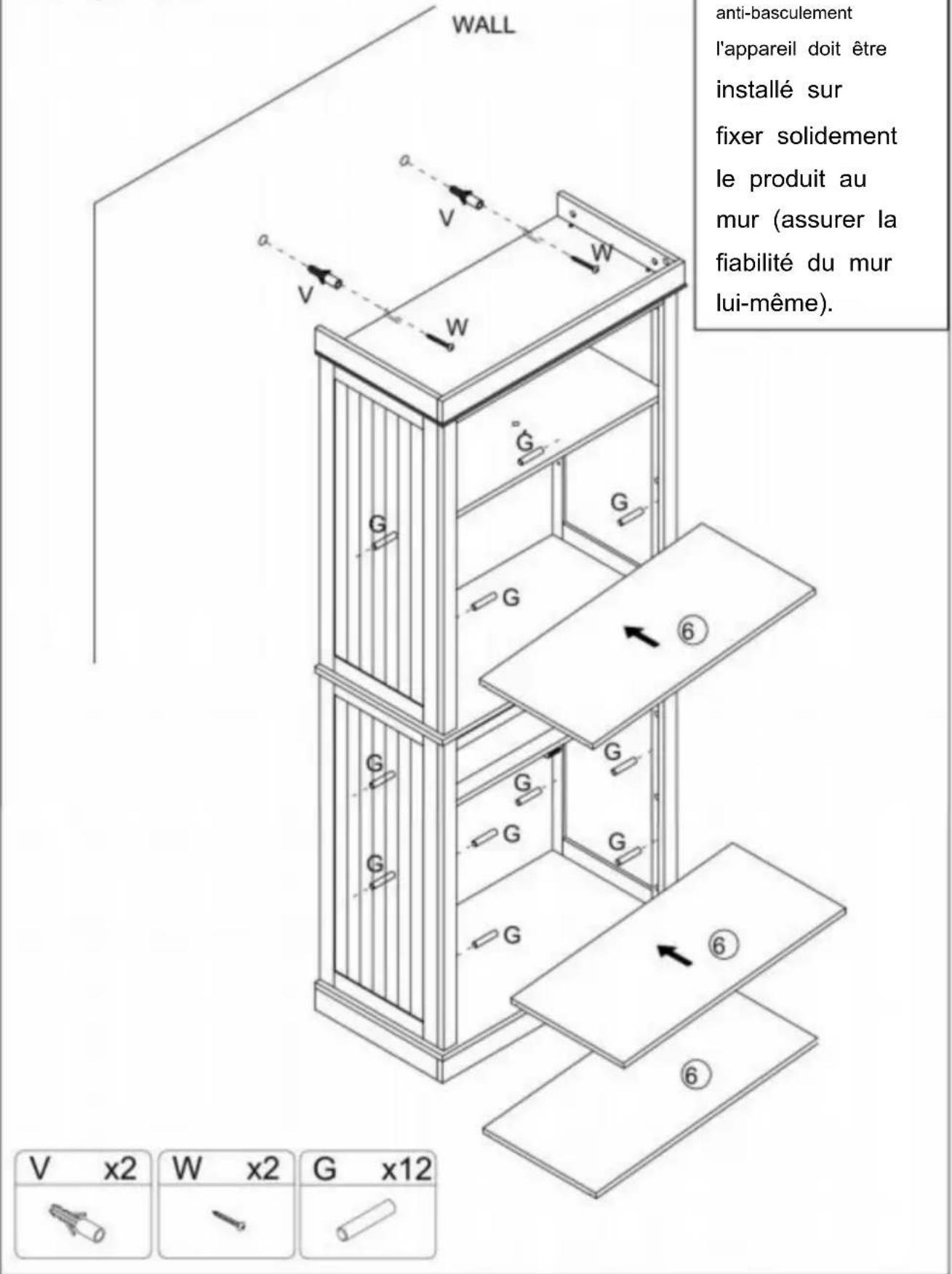
text_image
Technical diagram of a multi-level cabinet with labeled doors, doors, and directional arrows indicating assembly or movement.[IH 1x4] p x4l rp\~x2oi [Q^4]

text_image
1 9 1Étape 21
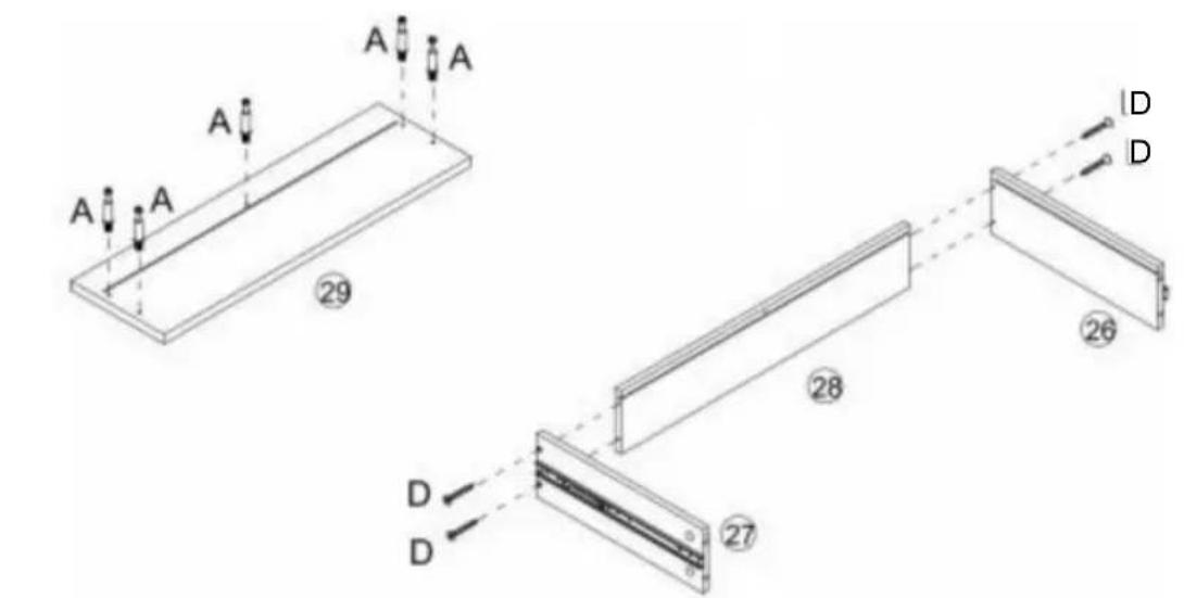
text_image
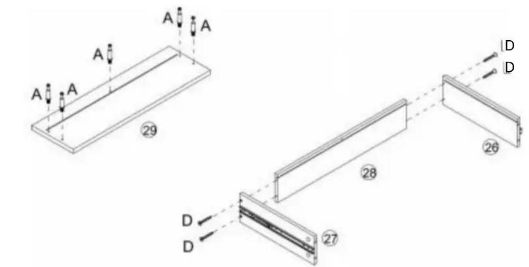
A A A A 29 28 26 D D 27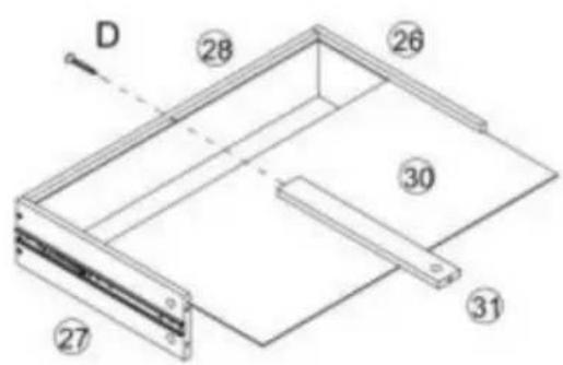
text_image
D 28 26 30 31 27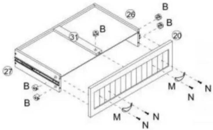
text_image
Technical diagram of a structural frame with labeled components and directional arrows indicating force or movement.| A x5 | D x5 | B x5 | M x2 | N x4 |
Étape 22
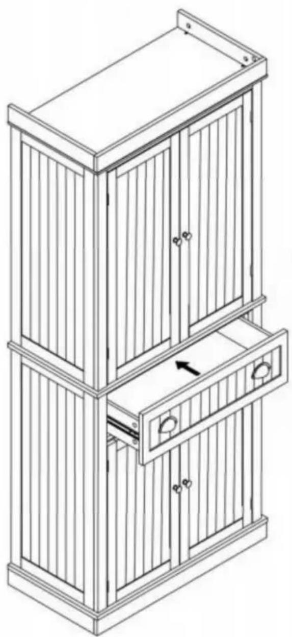
natural_image
Line drawing of a multi-tiered wooden cabinet with vertical slats and doorways (no text or symbols)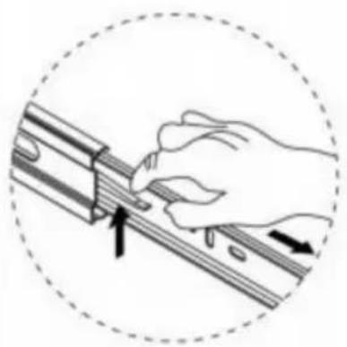
natural_image
Illustration of a hand using a tool to adjust or install a mechanical component, enclosed in a dashed circular border (no text or symbols)natural_image
Line drawing of a two-tiered cabinet with doors and drawers (no text or symbols)www.vevor.com/support
text_image
Exploded view diagram of a cabinet with numbered compartments and door frame layout
x45l B
ist die
Schritt 1
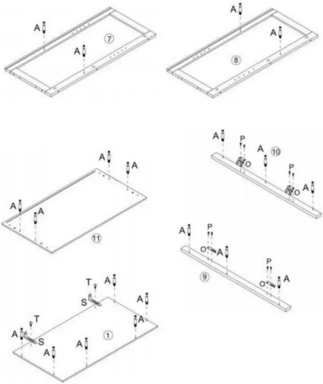

text_image
S x2 T x2 P x8 O x4 A x20Step 2
text_image
Technical diagram of a structural frame with labeled components and dimensions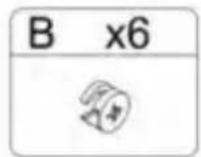
Schritt 4
text_image
E E E J K K C C C ① B C C E x4 ⑦ ⑧
Schritt 5
text_image
③ B ④ B ② A A ③ x2 x4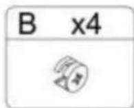
Schritt 6
text_image
B x6Step 7
text_image
Technical diagram of a modular drawer with numbered compartments and directional arrows indicating movement or flow.Step 8
text_image
Step F x4 E x4 ⑧ ⑦ F F E ⑪ E E F E ⑨Schritt 9
text_image
D A D 18 14 A D 19 A C 15 A x4 D x4St
P Die
natural_image
Illustration of a hand using a tool to adjust or install a mechanical component, with arrows indicating direction (no text or symbols present)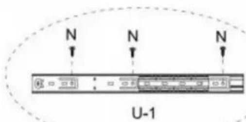
text_image
N N N U-1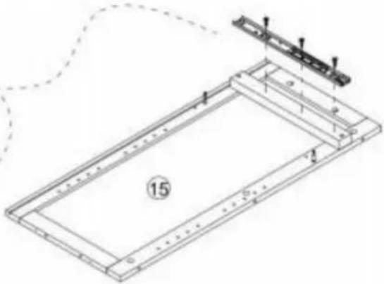
natural_image
Technical line drawing of a rectangular frame with internal components and a small bracket, no text or symbols present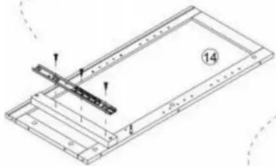
natural_image
Technical line drawing of a mechanical assembly with no visible text or symbols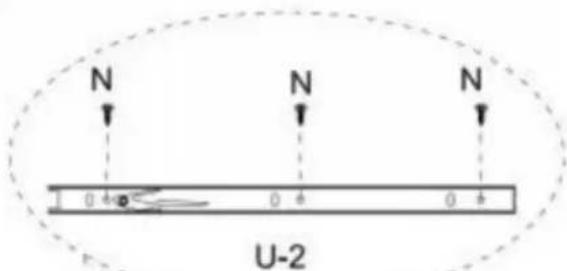
text_image
N N N 0 4 0 4 0 4 U-2
natural_image
Technical diagram of a mechanical assembly with two parallel strips and mounting holes (no text or symbols)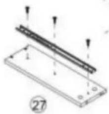
natural_image
Technical diagram of a mechanical assembly with labeled components and arrows indicating motion (no text or symbols present)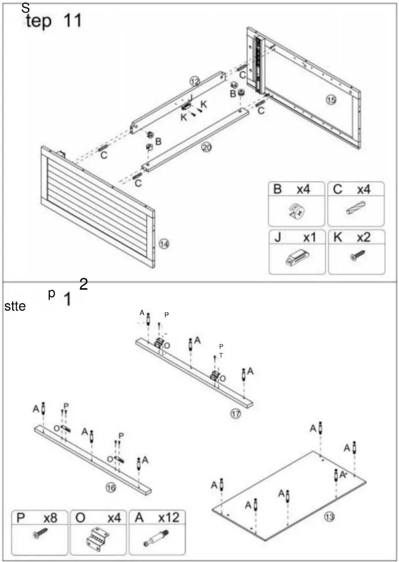
B x4 | C x4 |
| J x1 | K x2 |
| J x1 | K x2 |
 |  |
Schritt 13
text_image
Technical diagram of a structural frame assembly with numbered components and labeled parts B and flanges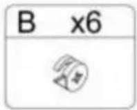
Step 14
text_image
C x4 ⑭ ⑮ ⑯ ⑰ ⑱ ⑲ ⑳ ⑴ C C C E E E E
Schritt 15
text_image
Technical diagram of a mechanical device with numbered components and directional arrows indicating assembly or movement.Schritt 17
natural_image
Isometric line drawing of a two-compartment electronic device with internal components and mounting holes (no text or symbols)
Schritt 18
text_image
Technical diagram of a multi-level cabinet with labeled R-R and directional arrows, including an inset showing a switch labeled L and switch K.K x16] IL\~x16j R x8]

1 J

Step 19
text_image
Technical diagram of a multi-level cabinet with labeled doors, doors, and directional arrows indicating assembly or movement.IH 1x4] p x4l rp\~x2oi [Q^4]

text_image
1 9 1Schritt 21
| A x5 | D x5 | B x5 | M x2 | N x4 |
 |  | [BA3H] |  |  |
Schritt 22
natural_image
Line drawing of a multi-tiered wooden cabinet with vertical slats and doorways (no text or symbols)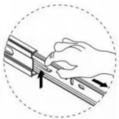
natural_image
Illustration of a hand using a tool to adjust or install a mechanical component, enclosed in a dashed circular border (no text or symbols)www.vevor.com/support
VEVILR®
TOCCAREH A BISS, HALF P
natural_image
Line drawing of a two-tiered cabinet with doors and drawers (no text or symbols)text_image
Exploded view diagram of a cabinet or enclosure with numbered components for identification.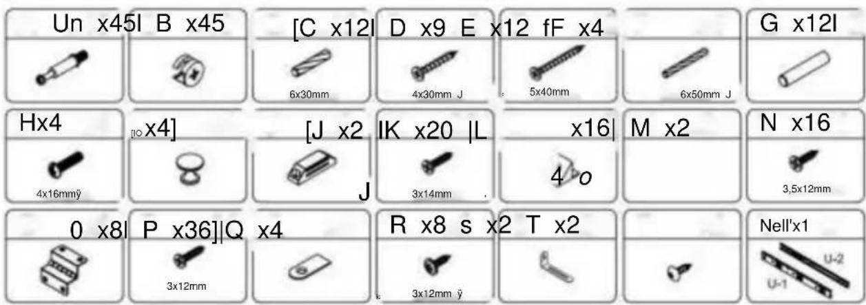
text_image
Un x45l B x45 [C x12l D x9 E x12 fF x4 G x12l 6x30mm 4x30mm J 5x40mm 6x50mm J Hx4 [o x4] [J x2 IK x20 |L x16| M x2 N x16 4x16mmÿ J 3x14mm 4 o 3,5x12mm 0 x8 P x36]Q x4 R x8 s x2 T x2 3x12mm 3x12mm ÿ Nell'x1 U-1 U-2
text_image
S x2 T x2 P x8 O x4 A x20Step 2
text_image
Technical diagram of a structural frame with labeled components and dimensions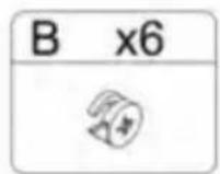
Passo 4
text_image
E E E J K K C C C ① B C C E x4 ⑦ ⑧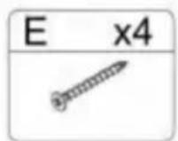
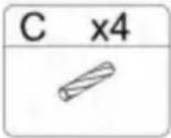
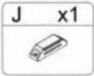
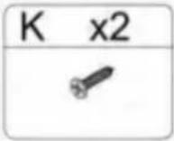
Passo 5
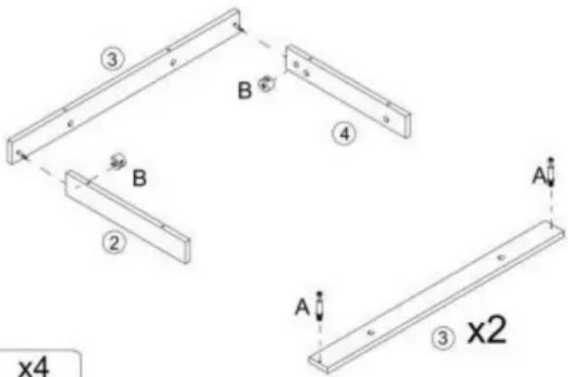
text_image
③ B ④ B ② A A ③ x2 x4
Passo 6
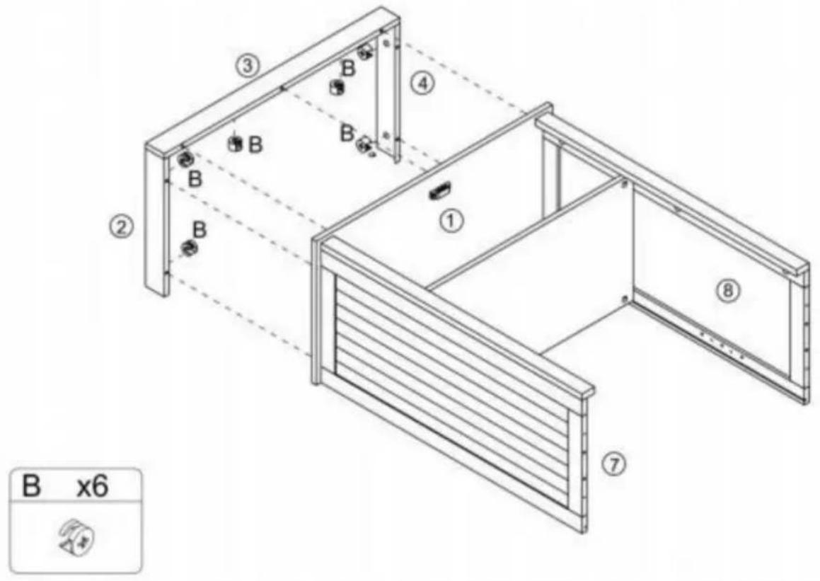
text_image
B x6Step 7
text_image
Technical diagram of a modular drawer with numbered compartments and directional arrows indicating movement or flow.Step 8
text_image
Step F x4 E x4 ⑧ ⑦ F F ⑪ E E F E EPasso 9
text_image
D 18 A D 14 A D 19 A C 15 A x4 D x4
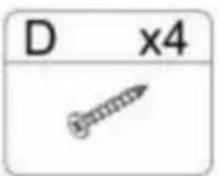
S
P-IL
text_image
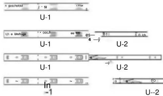
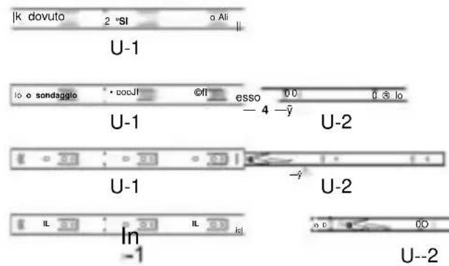
|k dovuto 2 °SI o Ali U-1 lo o sondaggio • docJl ©fl esso 00 0 5 lo U-1 -4 -y U-2 U-1 -y U-2 IL IL In -1 U--2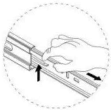
natural_image
Illustration of a hand using a tool to adjust or install a mechanical component, with arrows indicating direction (no text or symbols)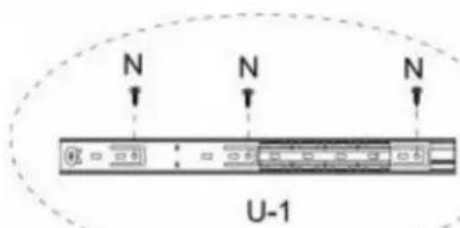
text_image
N N N U-1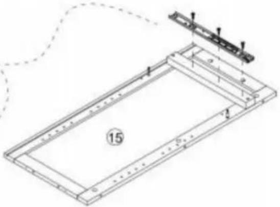
natural_image
Technical line drawing of a rectangular frame with internal components and a small bracket, no text or symbols present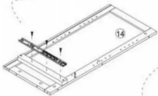
natural_image
Technical line drawing of a mechanical assembly with no visible text or symbols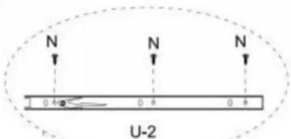
text_image
N N N 0.4 A 0.4 A 0.4 A U-2
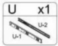
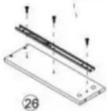
natural_image
Technical diagram of a mechanical assembly with two parallel strips and a base plate, no text or symbols present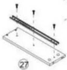
natural_image
Technical diagram of a mechanical assembly with labeled components and arrows indicating motion (no text or symbols present)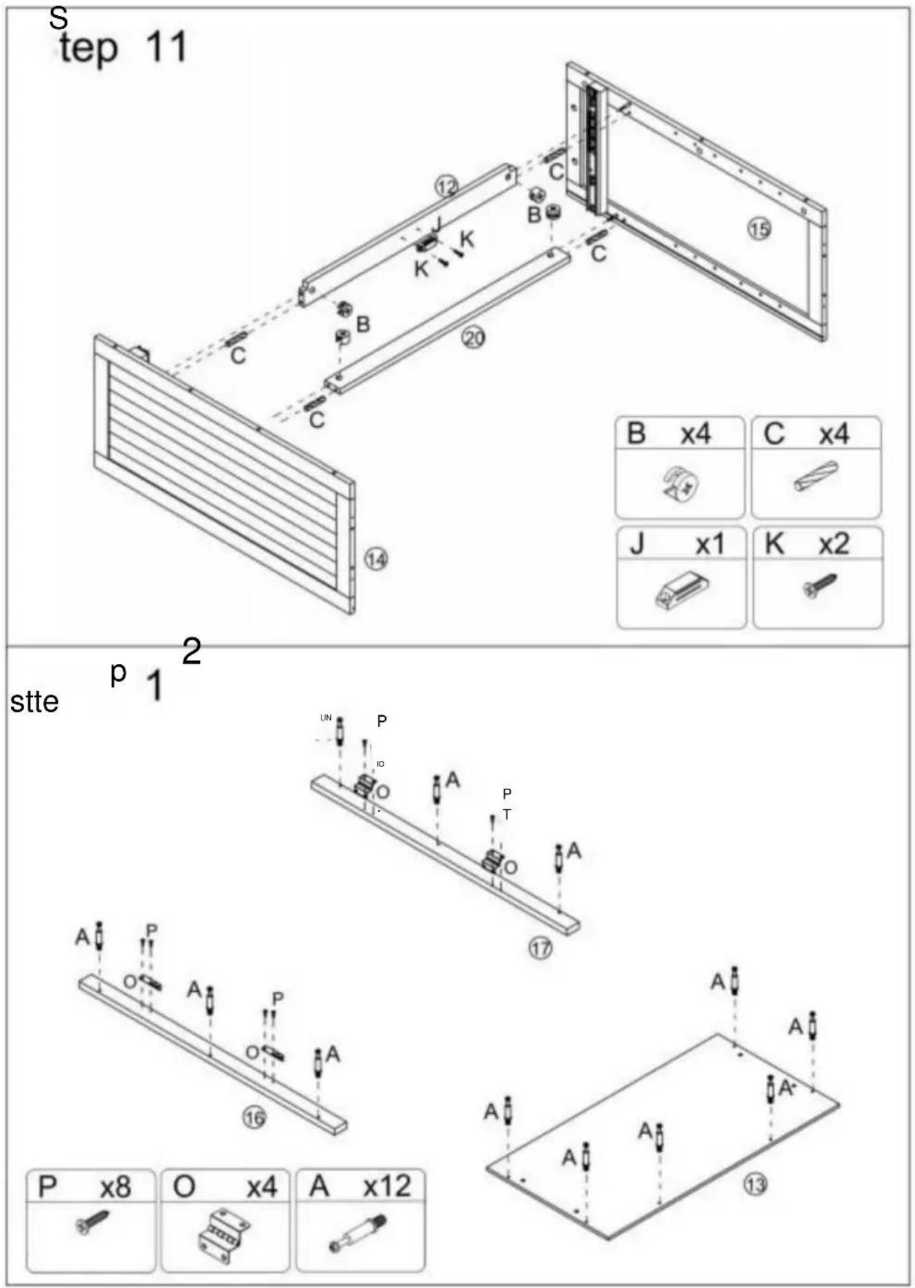
| B x4 | C x4 |
| J x1 | K x2 |
| J x1 | K x2 |
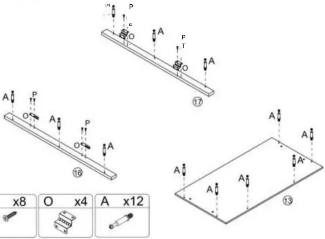
Passo 13
text_image
Technical diagram of a structural frame assembly with numbered components and labeled parts B and flanges
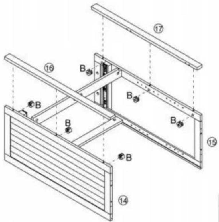
Step 14

text_image
C x4 ⑭ ⑮ ⑯ ⑰ ⑱ ⑲ ⑳ ⑪ ⑫ ⑬ ⑭ ⑮ ⑯ ⑰ ⑱ ⑲ ⑳ ⑪ ⑫ ⑬ ⑭ ⑮ ⑯ ⑰ ⑱ ⑲ ⑳
Passo 15
text_image
Technical diagram of a mechanical device with numbered components and directional arrows indicating assembly or movement.Passo 17
natural_image
Isometric line drawing of a two-compartment electronic device with internal components and mounting holes (no text or symbols)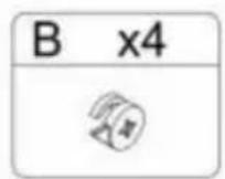
Passo 18
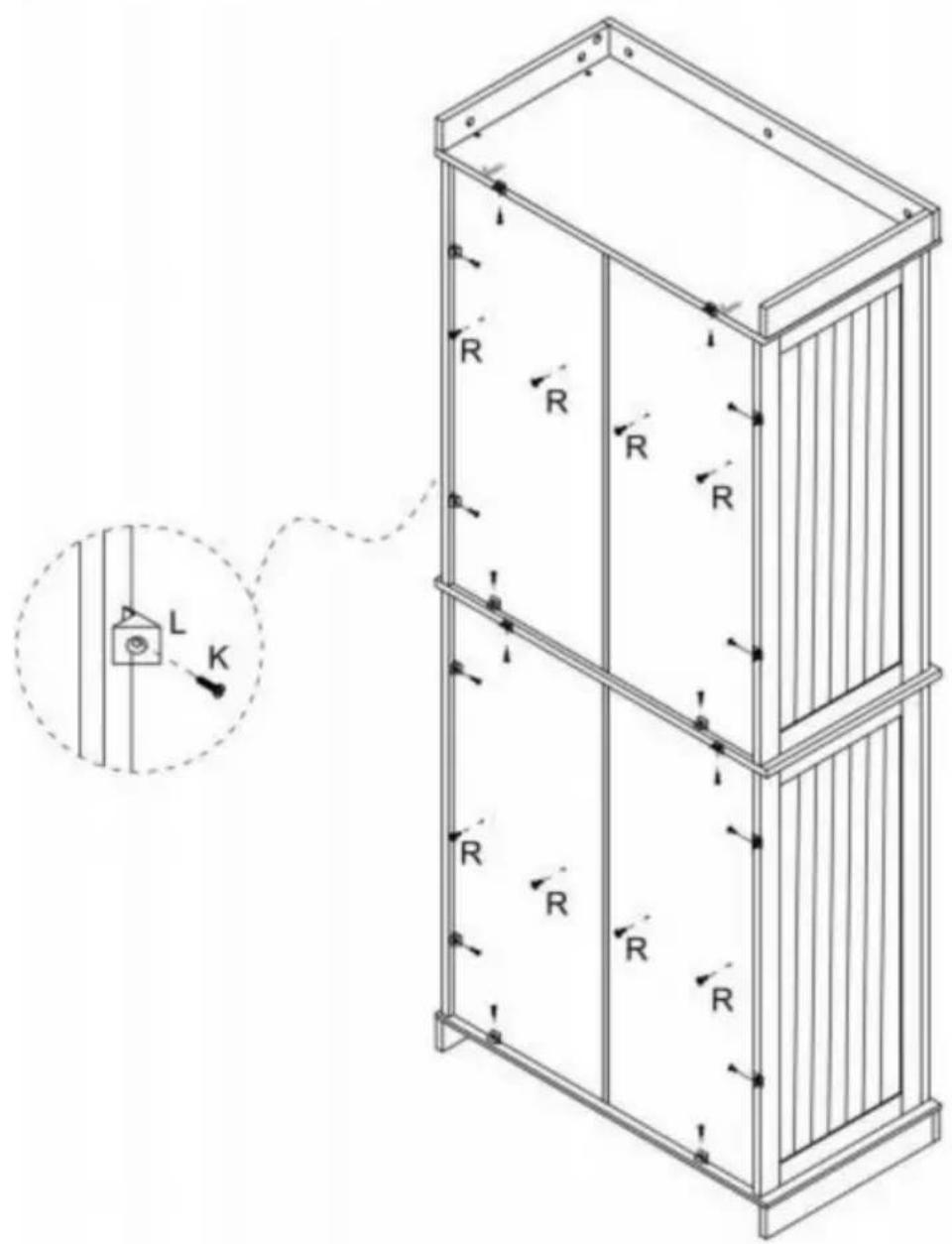
text_image
Technical diagram of a multi-level cabinet with labeled R-R and directional arrows, including an inset showing a switch labeled L and switch K.K x16] IL\~x16j R x8]

1 anno

Step 19
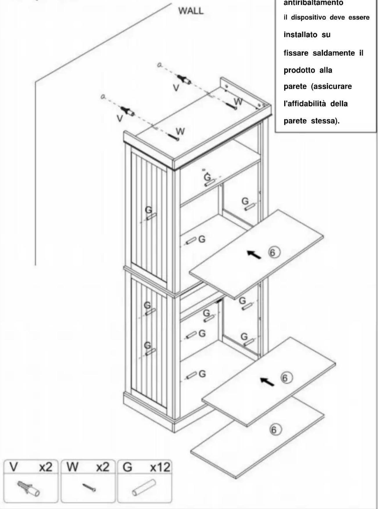
text_image
Technical diagram of a multi-level cabinet with labeled doors, doors, and directional arrows indicating assembly or movement.x4l rp\~x2oi [Q^4]
[IH 1x4]

1 9


Passo 21
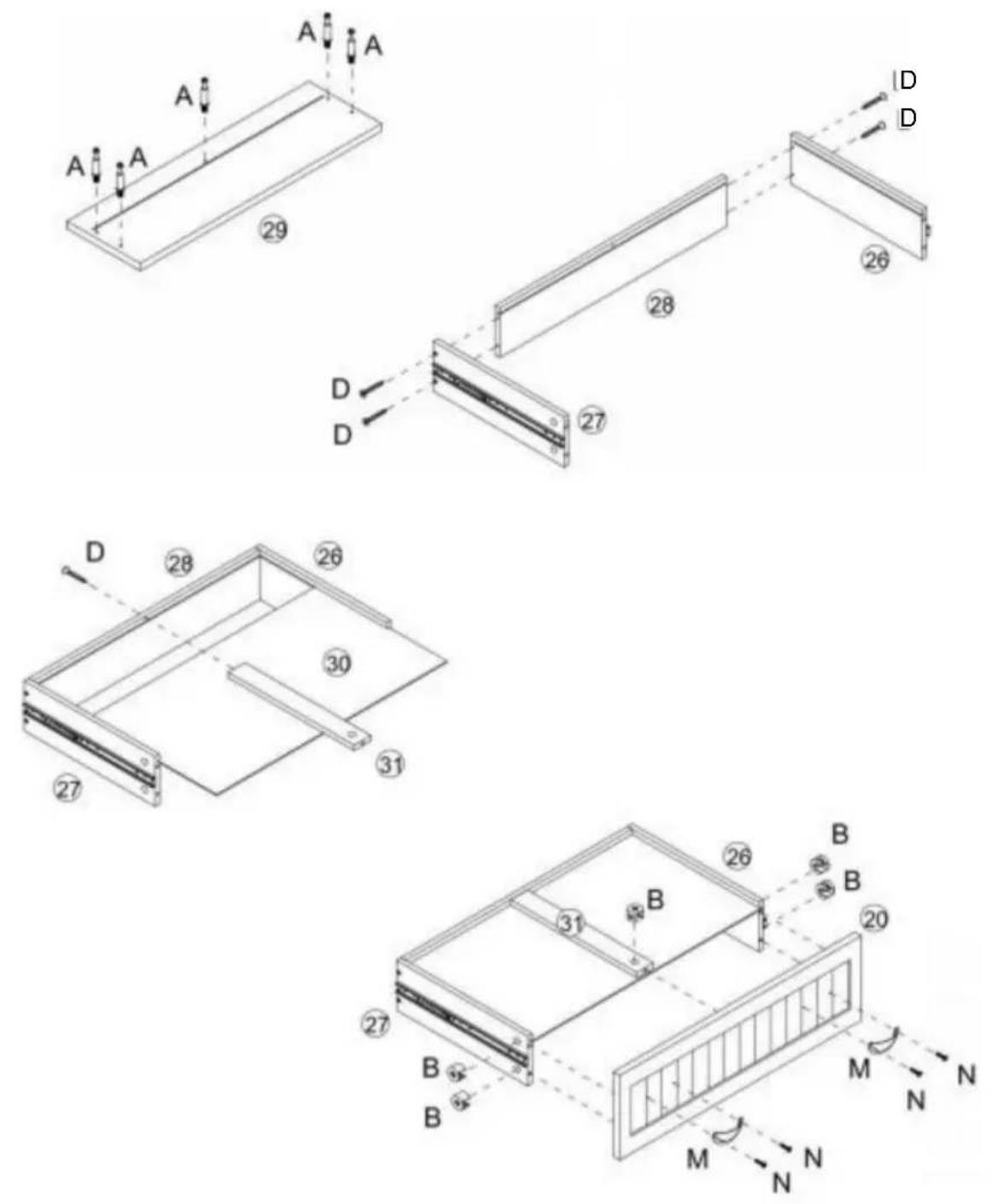
| A x5 | D x5 | B x5 | M x2 | N x4 |
Passo 22
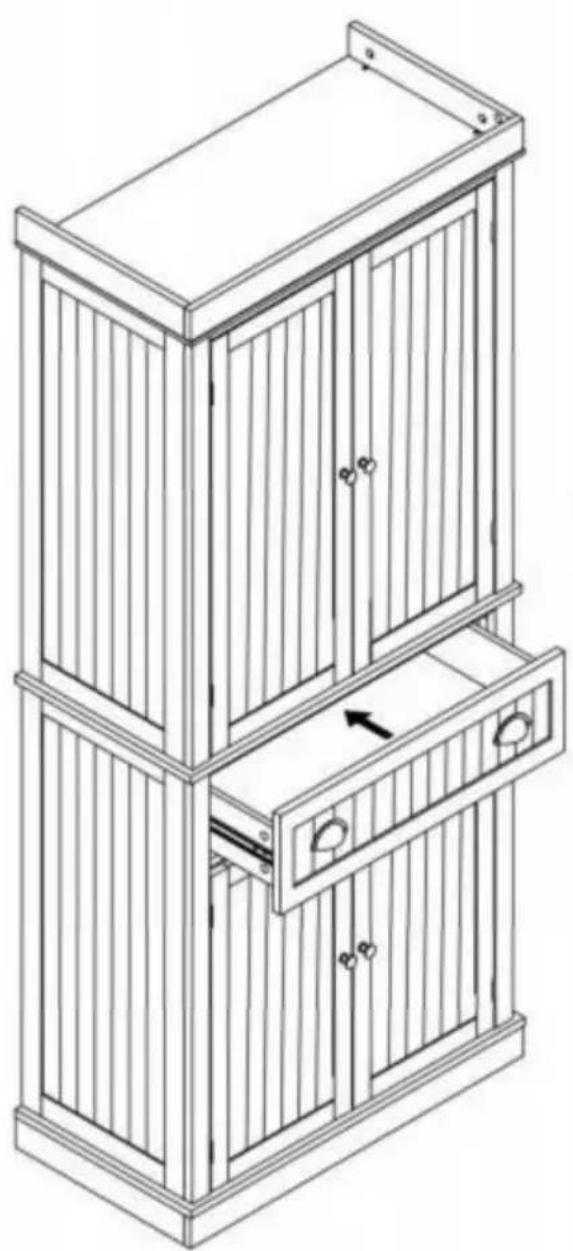
natural_image
Line drawing of a multi-tiered wooden cabinet with vertical slats and doorways (no text or symbols)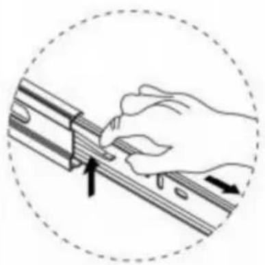
natural_image
Illustration of a hand using a tool to adjust or install a mechanical component, enclosed in a dashed circular border (no text or symbols)elettronica www.vevor.com/support
V Y V ELR ^®
TOGOH A ARS, Z HALF P
natural_image
Line drawing of a two-tiered cabinet with doors and drawers (no text or symbols)text_image
Exploded view diagram of a 30-pin door assembly with numbered components for identification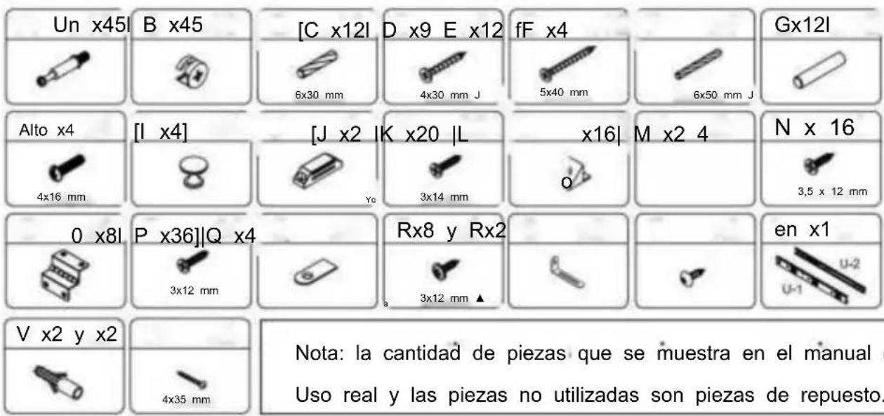
text_image
S x2 T x2 P x8 O x4 A x20Step 2
text_image
Technical diagram of a structural frame with labeled components and dimensions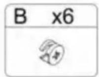
Paso 4
text_image
E E J K K C C C ① B C C E E x4 ⑦ ⑧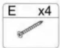
Paso 5
text_image
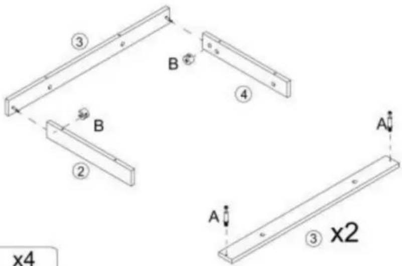
③ B ④ B ② A A ③ x2 x4
Paso 6
text_image
B x6Step 7

text_image
Technical diagram of a modular drawer with numbered compartments and directional arrows indicating movement or flow.Step 8
text_image
x4 E x4 ⑧ ⑦ F F E ⑪ E E F E x4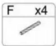
Paso 9
text_image
D A D A ⑱ ⑭ ⑭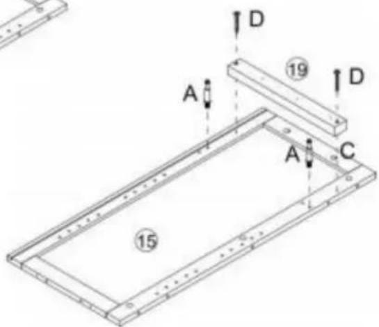
text_image
A D 19 D A C 15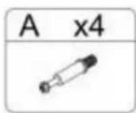
Calle
natural_image
Illustration of a hand using a tool to adjust or install a mechanical component, with arrows indicating direction (no text or symbols)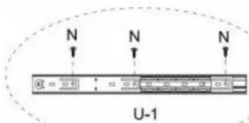
text_image
N N N U-1
natural_image
Technical line drawing of a rectangular frame with internal components and a small bracket, no text or symbols present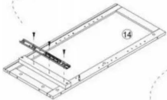
natural_image
Technical line drawing of a mechanical assembly with no visible text or symbols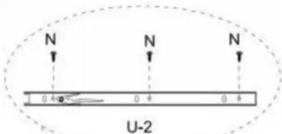
text_image
N N N 0 4 0 4 0 4 U-2
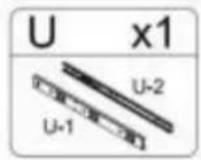
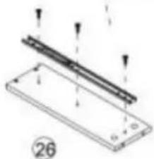
natural_image
Technical diagram of a mechanical assembly with two parallel strips and mounting holes (no text or symbols)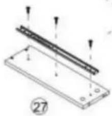
natural_image
Technical diagram of a mechanical assembly with labeled components and arrows indicating motion (no text or symbols present)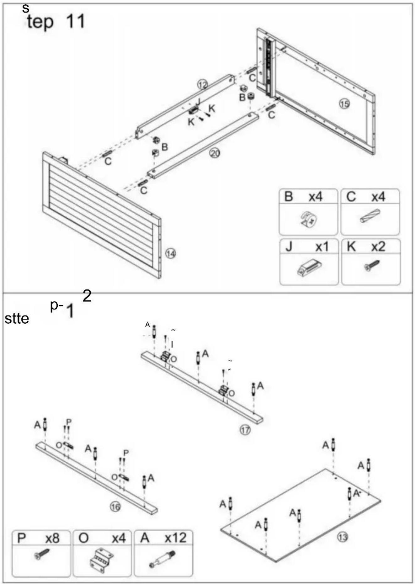
Paso 13
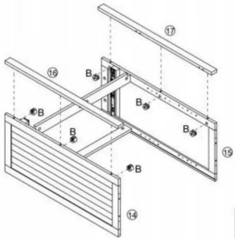
text_image
Technical diagram of a structural frame assembly with numbered components and labeled parts B and flanges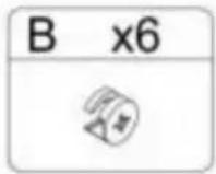
Step 14
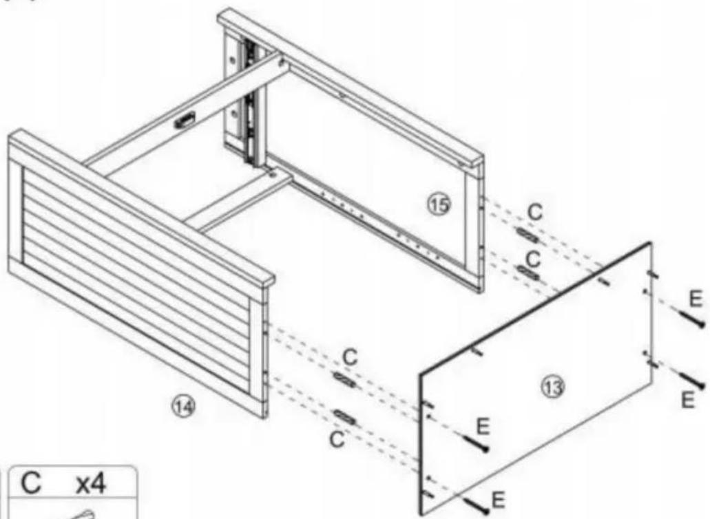
text_image
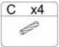
C x4 ⑭ ⑮ ⑯ ⑰ ⑱ ⑲ ⑳ ⑴ C C C E E E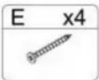
Paso 15
text_image
Technical diagram of a mechanical device with numbered components and directional arrows indicating assembly or movement.Paso 17
natural_image
Isometric line drawing of a two-compartment electronic device with internal components and mounting holes (no text or symbols)
Paso 18
text_image
Technical diagram of a multi-level cabinet with labeled R-R and directional arrows, including an inset showing a switch labeled L and switch K.K x16] IL\~x16j R x8 ]

1 j

Step 19
text_image
Technical diagram of a multi-level cabinet with labeled doors, doors, and directional arrows indicating assembly or movement.[IH 1x4] pág. x4l rp\~x2oi [Q^4]

1 9
1


Paso 21
| A x5 | D x5 | B x5 | M x2 | N x4 |
 |  |  |  |  |
Paso 22
natural_image
Line drawing of a two-tiered wooden cabinet with vertical slats and doorways, showing internal compartments and a handle (no text or symbols)
natural_image
Illustration of a hand using a tool to adjust or install a mechanical component, enclosed in a dashed circle (no text or symbols)natural_image
Line drawing of a two-tiered cabinet with doors and drawers (no text or symbols)POTRZEBUJESZ POMOCY? SKONTAKTUJ SIĘ Z NAMI!
text_image
Exploded view diagram of a 30-pin door assembly with numbered components for identification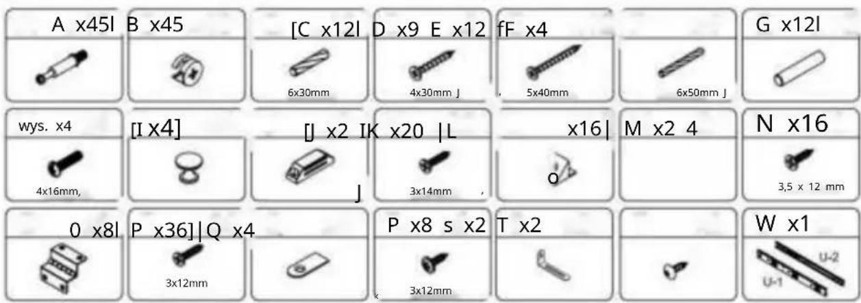
text_image
A x45l B x45 [C x12l D x9 E x12 fF x4 6x30mm 4x30mm J 5x40mm 6x50mm J wys. x4 [I x4] [J x2 IK x20 |L x16] M x2 4 N x16 4x16mm, j 3x14mm o 3,5 x 12 mm 0 x8l P x36l Q x4 P x8 s x2 T x2 W x1 3x12mm 3x12mm U-1 U-2
text_image
S x2 T x2 P x8 O x4 A x20Step 2
text_image
Technical diagram of a structural frame assembly with labeled components and dimensions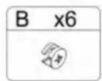
Krok 4
text_image
E E E J K K C C C ① B C C E x4 ⑦ 8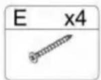
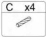
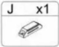
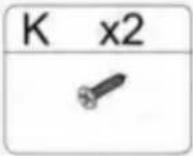
Krok 5
text_image
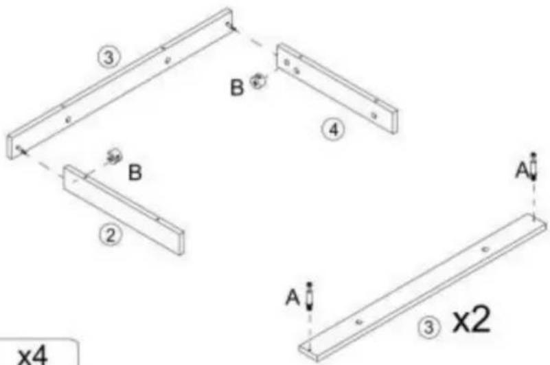
③ B ④ B ② A A ③ x2 x4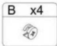
Krok 6
text_image
B x6Step 7
text_image
Technical diagram of a modular drawer with numbered compartments and directional arrows indicating movement or flow.Step 8
text_image
x4 E x4 ⑦ ⑧ F F E ⑪ E E F E x4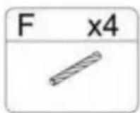
Krok 9
text_image
D A D A ⑱ ⑭ ⑭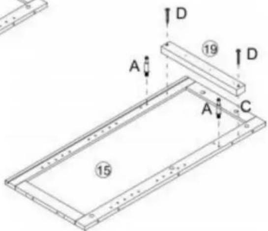
text_image
A D 19 D A C 15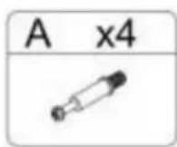
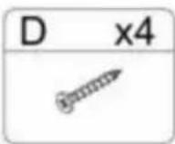
Św
P the
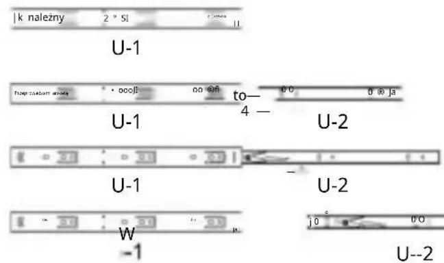
text_image
k należy 2 ° SI U-1 Toup custom armate 0.008 0.008 to— 4 — U-2 U-1 U-2 W -1 U--2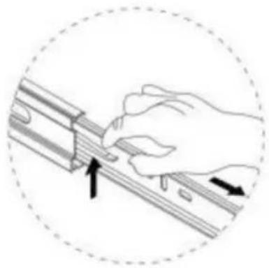
natural_image
Illustration of a hand using a tool to adjust or install a mechanical component, with arrows indicating direction (no text or symbols present)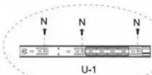
text_image
N N N U-1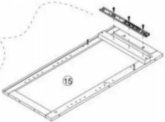
natural_image
Technical line drawing of a rectangular frame with internal components and a small bracket, no text or symbols present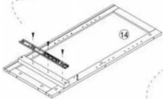
natural_image
Technical line drawing of a mechanical assembly with no visible text or symbols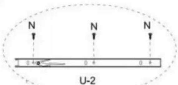
text_image
N N N 0 4 A 0 4 0 4 U-2
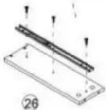
natural_image
Technical diagram of a mechanical assembly with two parallel strips and mounting holes (no text or symbols)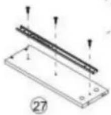
natural_image
Technical diagram of a mechanical assembly with labeled components and arrows indicating motion (no text or symbols present)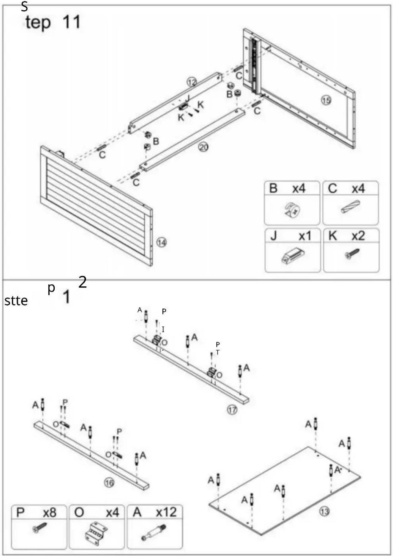
| B x4 | C x4 |
| J x1 | K x2 |
| J x1 | K x2 |
Krok 13
text_image
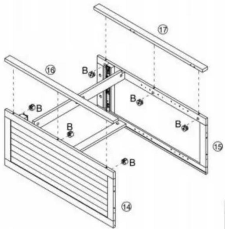
Technical diagram of a structural frame assembly with numbered components and labeled parts B and flanges
Step 14

text_image
C x4 ⑭ ⑮ ⑯ ⑰ ⑱ ⑲ ⑳ ⑴ C C C E E E E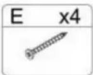
Krok 15
text_image
Technical diagram of a mechanical device with numbered components and directional arrows indicating assembly or movement.Krok 17
natural_image
Isometric line drawing of a two-compartment electronic device with internal components and mounting holes (no text or symbols)
Krok 18
text_image
Technical diagram of a multi-level cabinet with labeled R-R and directional arrows, including an inset showing a switch labeled L and switch K.K x16] IL\~x16j R x8]

text_image
1 dzieńStep 19
text_image
Technical diagram of a multi-level cabinet with labeled doors, doors, and directional arrows indicating assembly or movement.[IH 1x4] str x4l rp\~x2oi [Q^4]

1 9
1


Krok 21
text_image
A A A A 29 28 26 D D 27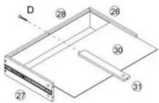
text_image
D 28 26 30 31 27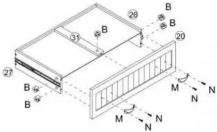
text_image
Technical diagram of a structural frame with labeled components and directional arrows indicating force or movement.| A x5 | D x5 | B x5 | M x2 | N x4 |
Krok 22
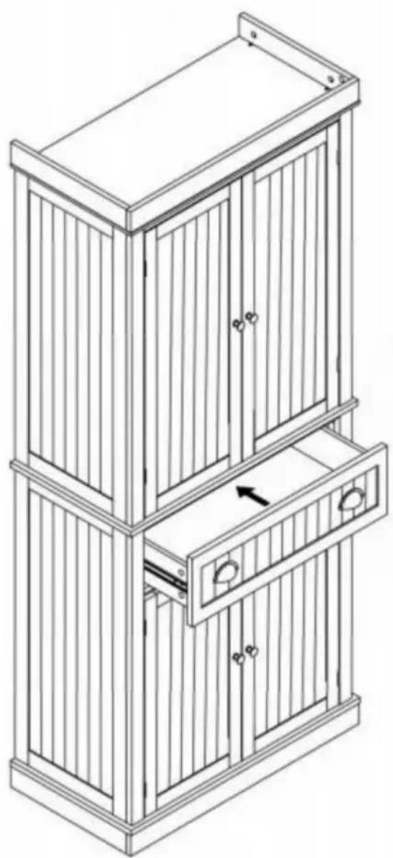
natural_image
Line drawing of a multi-tiered wooden cabinet with vertical slats and doorways (no text or symbols)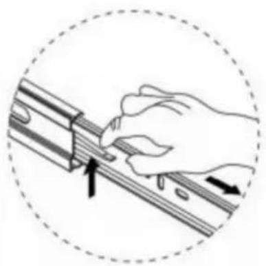
natural_image
Illustration of a hand using a tool to adjust or install a mechanical component, enclosed in a dashed circle (no text or symbols)natural_image
Line drawing of a two-tiered cabinet with doors and drawers (no text or symbols)HULP NODIG? NEEM CONTACT MET ONS OP!
text_image
Exploded view diagram of a 30-pin door assembly with numbered components for identification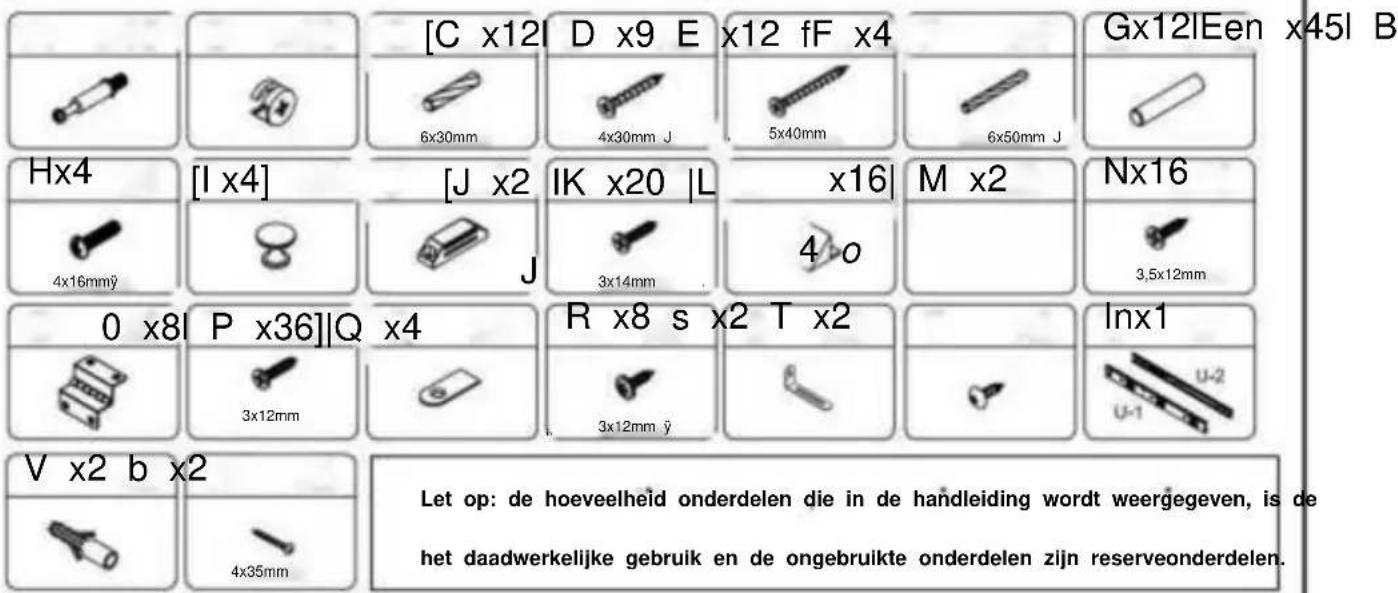
text_image
S x2 T x2 P x8 O x4 A x20Step 2
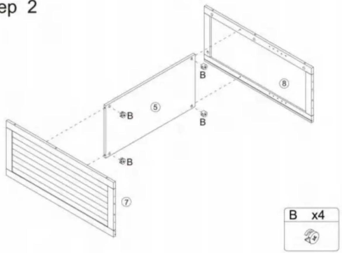
text_image
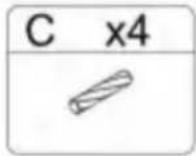
E E E J K K C C C ① B C C E x4 ⑦ 8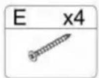
Stap 5
text_image
③ B ④ B ② A A ③ x2 x4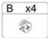
Stap 6
text_image
B x6Step 7
text_image
Technical diagram of a modular drawer with numbered compartments and directional arrows indicating movement or flow.Step 8
text_image
x4 E x4 ⑧ ⑦ F F E ⑪ E E F E x4
Stap 9
text_image
D A D A ⑱ ⑭ ⑭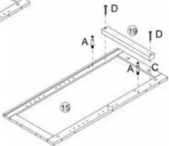
text_image
A D 19 D A C 15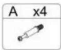
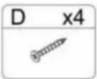
St
P de
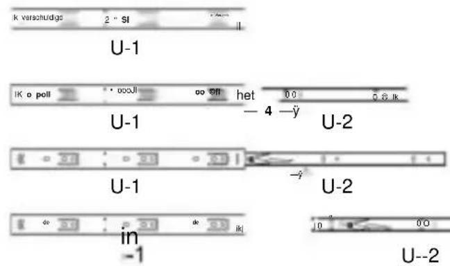
text_image
k verschuldige 2" SI II U-1 IK a poli oooJl oo off het 00 08 ik U-1 -4 -ÿ U-2 U-1 -ÿ U-2 in -1 U--2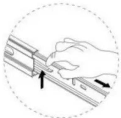
natural_image
Illustration of a hand using a tool to adjust or install a mechanical component, with arrows indicating direction (no text or symbols present)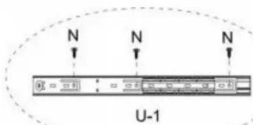
text_image
N N N U-1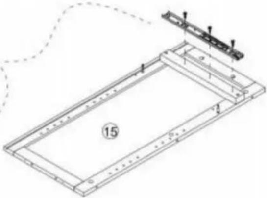
natural_image
Technical line drawing of a rectangular frame with internal components and a small bracket, no text or symbols present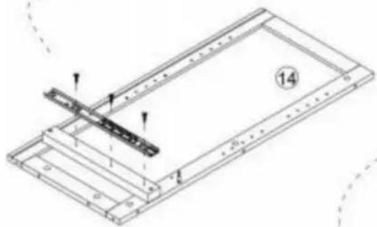
natural_image
Technical line drawing of a mechanical assembly with no visible text or symbols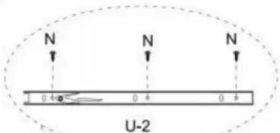
text_image
N N N 0 4 0 4 0 4 U-2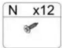
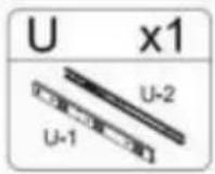
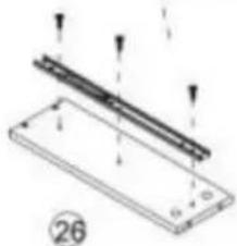
natural_image
Technical diagram of a mechanical assembly with two parallel strips and mounting holes (no text or symbols)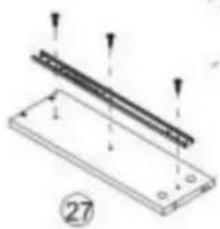
natural_image
Technical diagram of a mechanical assembly with labeled components and arrows indicating motion (no text or symbols present)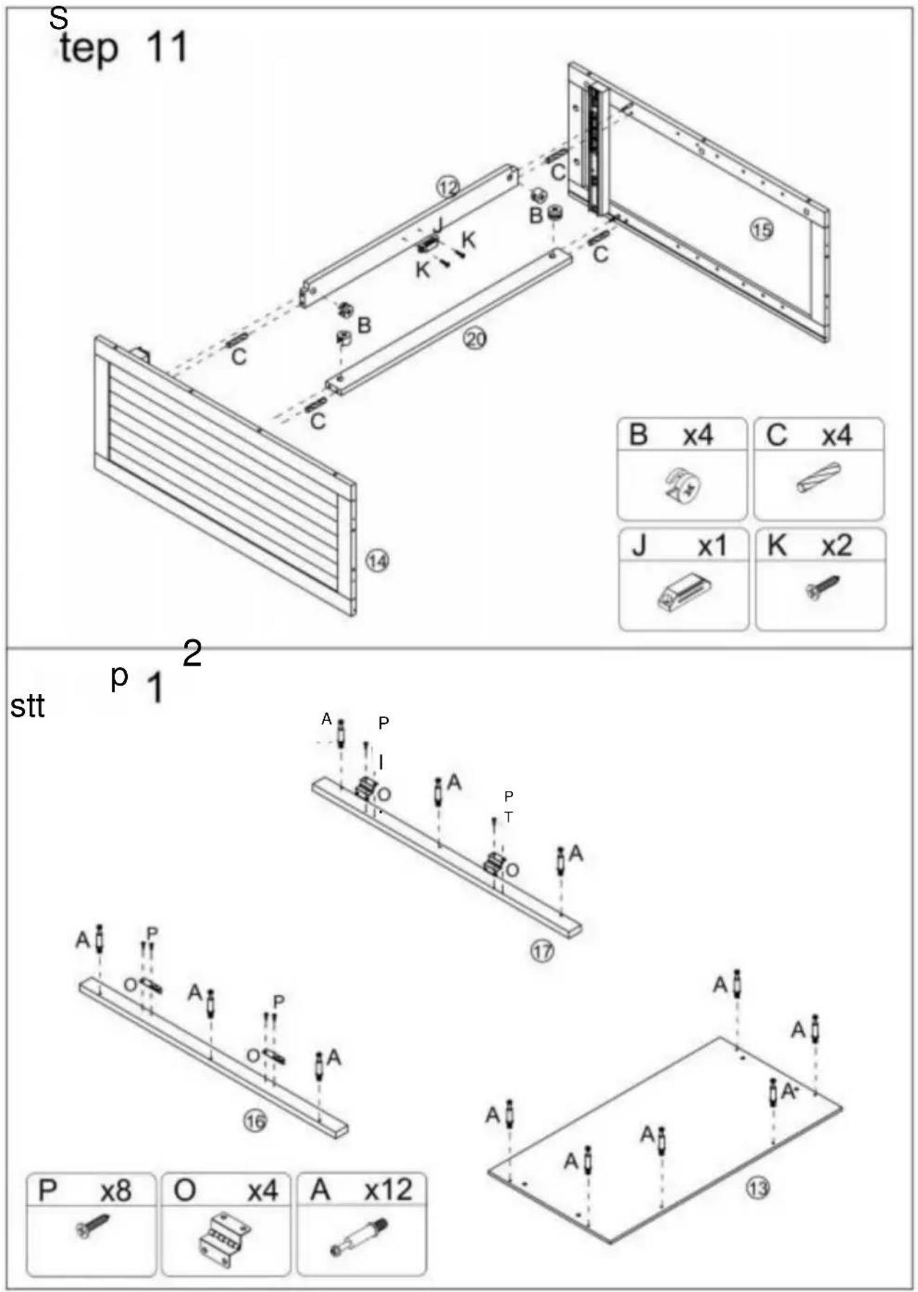
| B x4 | C x4 |
| J x1 | K x2 |
| J x1 | K x2 |
Stap 13
text_image
Technical diagram of a structural frame assembly with numbered components and labeled parts B and flanges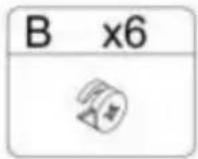
Step 14
text_image
C x4 ⑭ ⑮ ⑭ ⑮ ⑮ ⑮ ⑮ ⑮ ⑮ ⑮ ⑮ ⑮ ⑮ ⑮ ⑮ ⑮ ⑮ ⑮ ⑮ ⑮ ⑮ ⑮ ⑮ ⑮ ⑮ ⑮ ⑮ ⑮ ⑮ ⑮ ⑮ ⑮ ⑮ ⑮ ⑮ ⑮ ⑮
Stap 15
text_image
Technical diagram of a mechanical device with numbered components and directional arrows indicating assembly or movement.Stap 17
natural_image
Isometric line drawing of a two-compartment electronic device with internal components and mounting holes (no text or symbols)
Stap 18
text_image
Technical diagram of a multi-level cabinet with labeled R-R and directional arrows, including an inset showing a switch labeled L and switch K.K x16] IL\~x16j R x8 ]

1 jaar

Step 19
text_image
Technical diagram of a multi-level cabinet with labeled components and directional arrows indicating flow or movement.IH 1x4] p x4l rp\~x2oi [Q^4]

text_image
1 9 1Stap 21
text_image
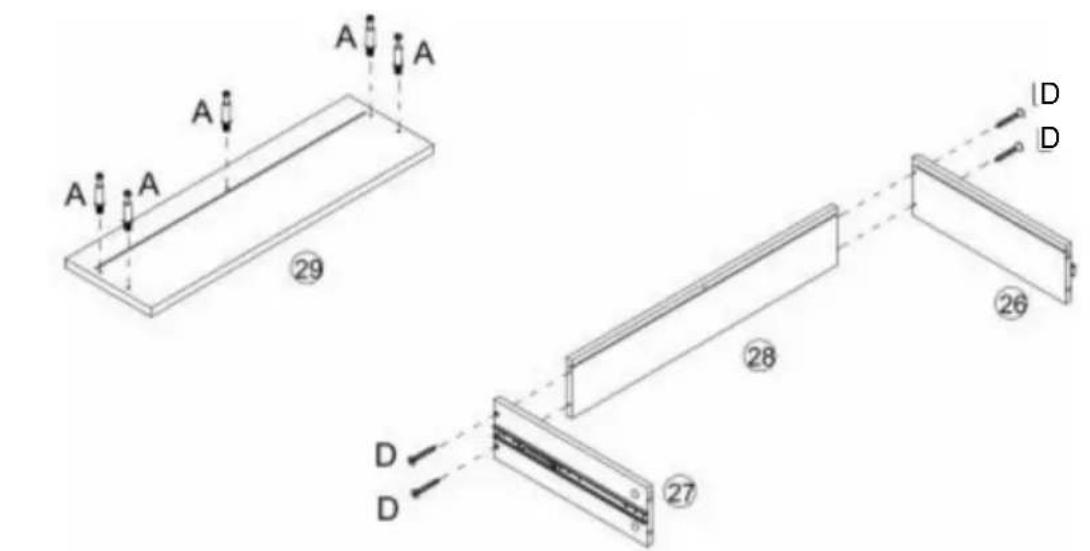
A A A A 29 28 26 D D 27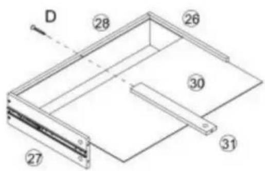
text_image
D 28 26 30 31 27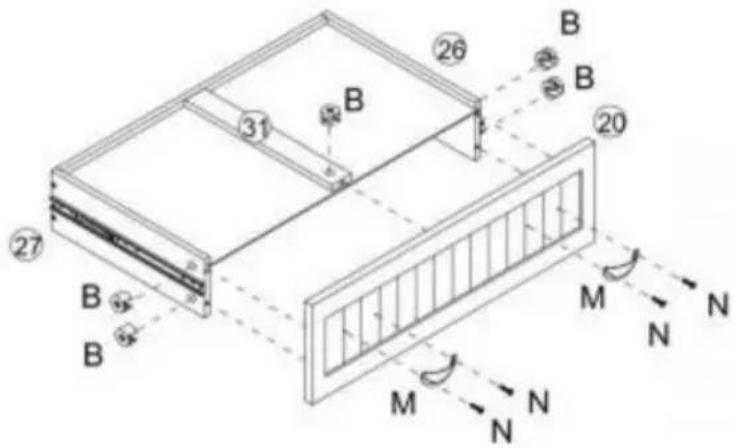
text_image
Technical diagram of a structural frame with labeled components and directional arrows indicating force or movement.| A x5 | D x5 | B x5 | M x2 | N x4 |
Stap 22
natural_image
Line drawing of a multi-tiered wooden cabinet with vertical slats and doorways (no text or symbols)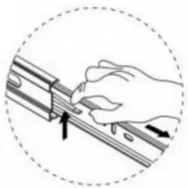
natural_image
Illustration of a hand using a tool to adjust or install a mechanical component, enclosed in a dashed circle (no text or symbols)garantiecertificaat www.vevor.com/support
OCHV DER®
OLS, HALF PRISH TILLTUGT
natural_image
Line drawing of a two-tiered cabinet with doors and drawers (no text or symbols)BEHÖVER HJÄLP? KONTAKTA OSS!
www.vevor.com/support
text_image
Exploded view diagram of a 30-pin door assembly with numbered components for identification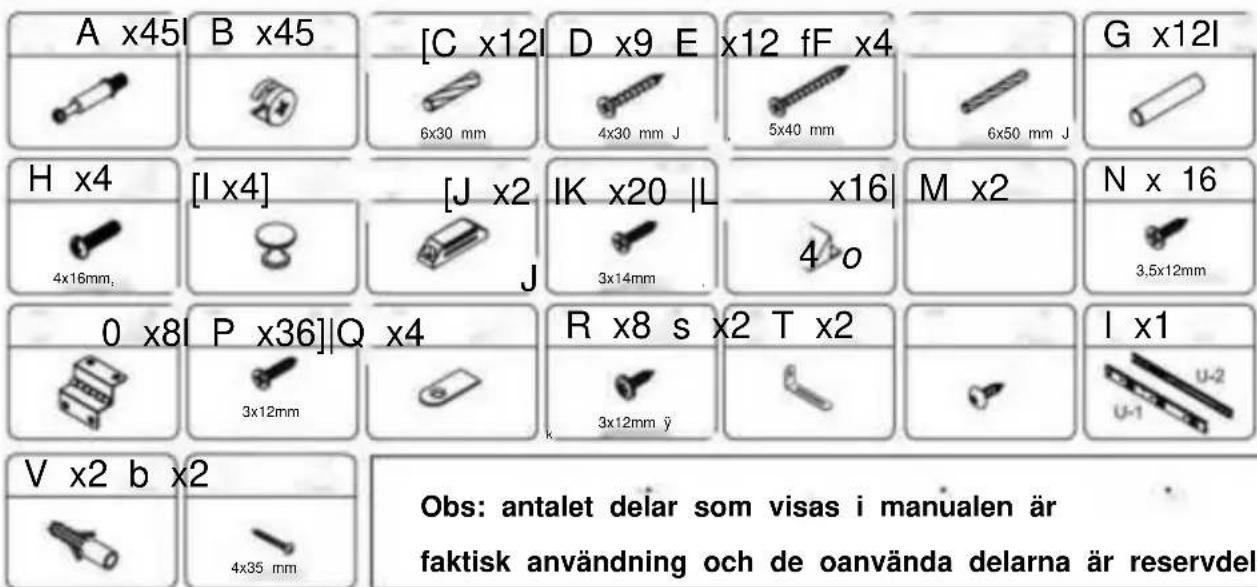
text_image
S x2 T x2 P x8 O x4 A x20Step 2
text_image
Technical diagram of a structural frame with labeled components and dimensions
Steg 4

text_image
E E J K K C C C ① B C C E E x4 ⑦ 8
Steg 5
text_image
③ B ④ B ② A A ③ x2 x4
text_image
B x4 A x4Steg 6
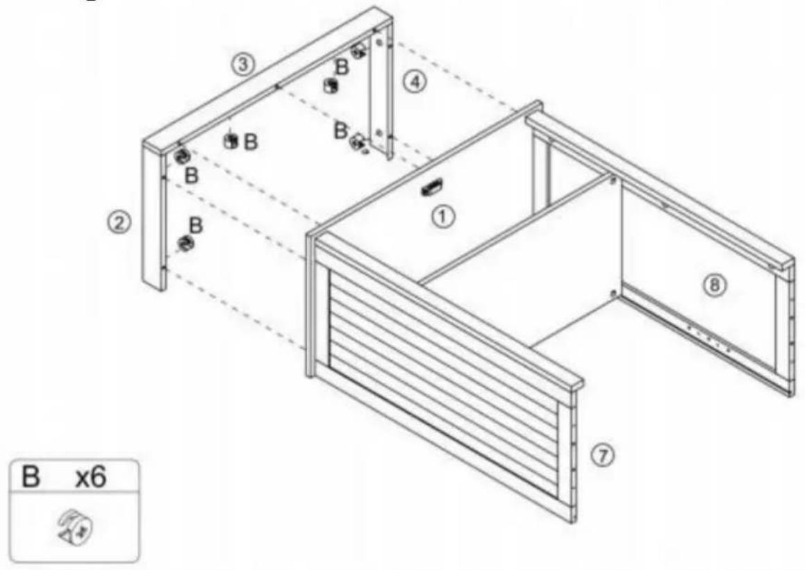
text_image
B x6Step 7
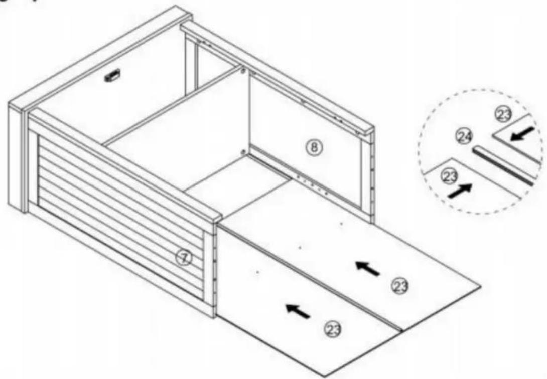
text_image
Technical diagram of a modular drawer with numbered compartments and directional arrows indicating movement or flow.Step 8
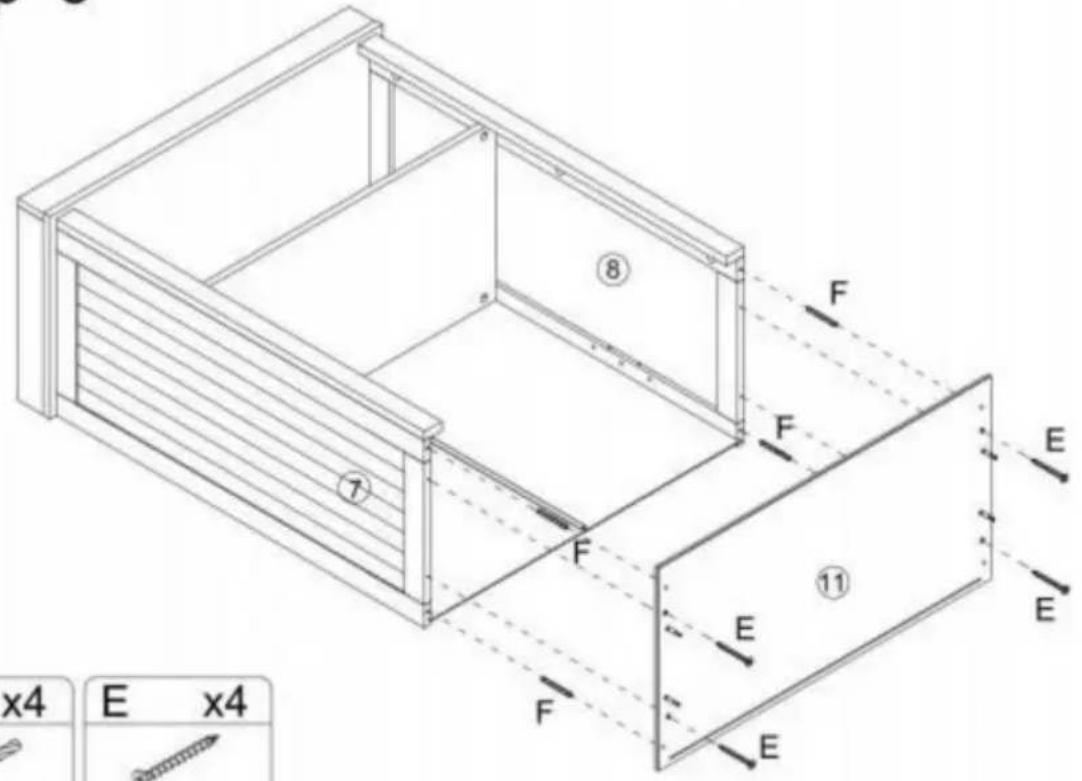
text_image
x4 E x4 ⑧ ⑦ F F E ⑪ E E F E x4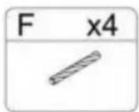
Steg 9
text_image
D A D A ⑱ ⑭ ⑭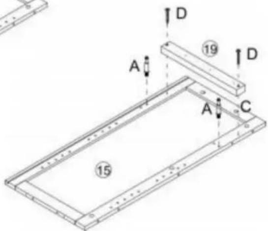
text_image
A D 19 D A C 15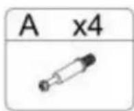
St

text_image
k pa grund av 2 SI v.04 II U-1 Jag omröstning • ooJl oo off det 0 0 0 0 1 U-1 — 4 —ÿ U-2 U-1 -ÿ U-2 de 30 de 50 il 0 0 0 0 I -1 U--2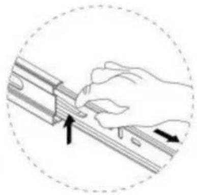
natural_image
Illustration of a hand using a tool to adjust or install a mechanical component, with arrows indicating direction (no text or symbols)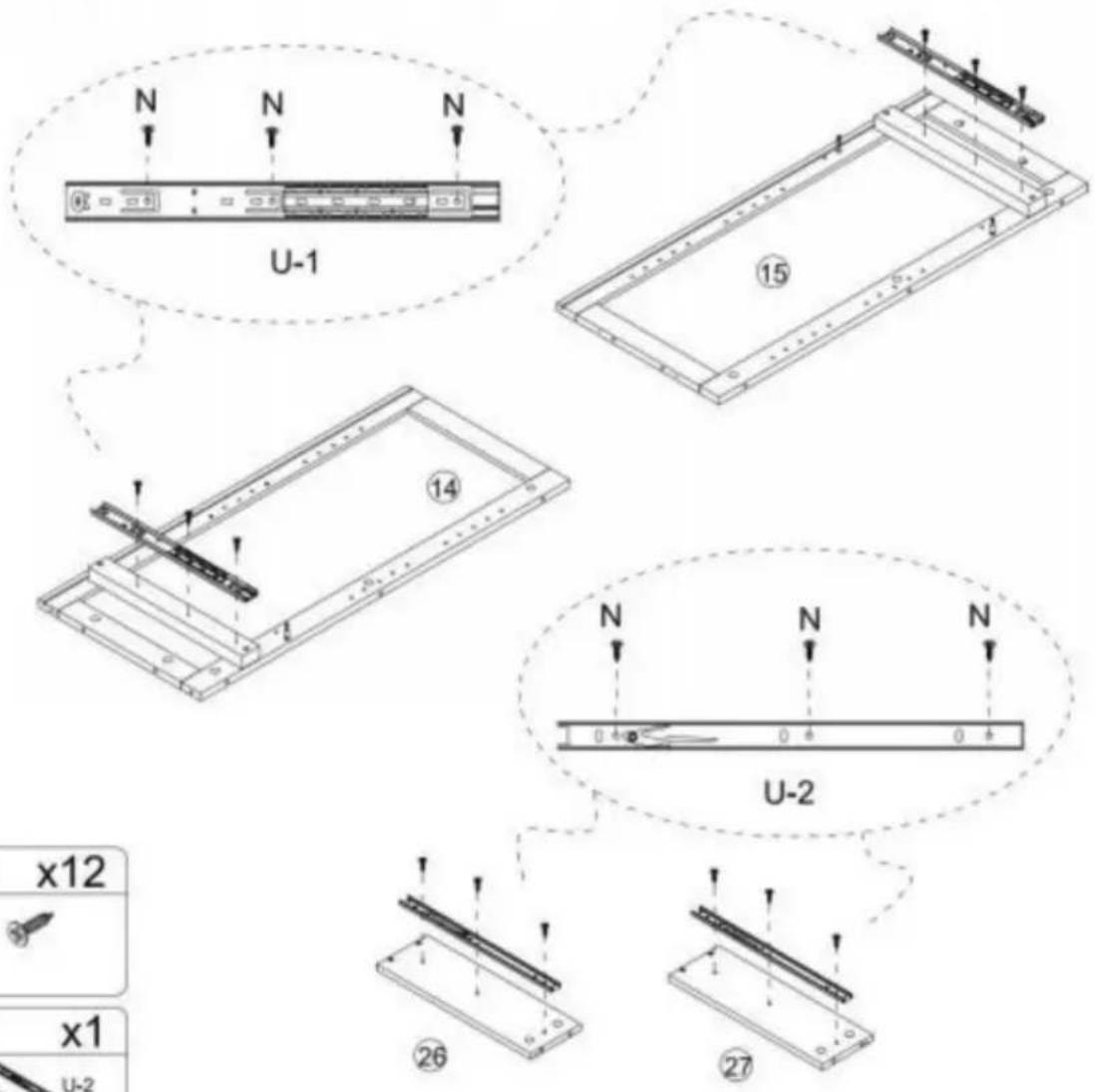
text_image
N N N U-1 ⑮ ⑭ 14 N N N 0 0 0 U-2 x12 x1 U-2 ②6 ②7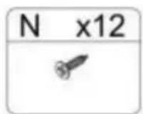
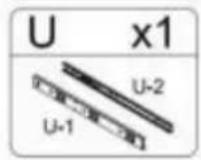
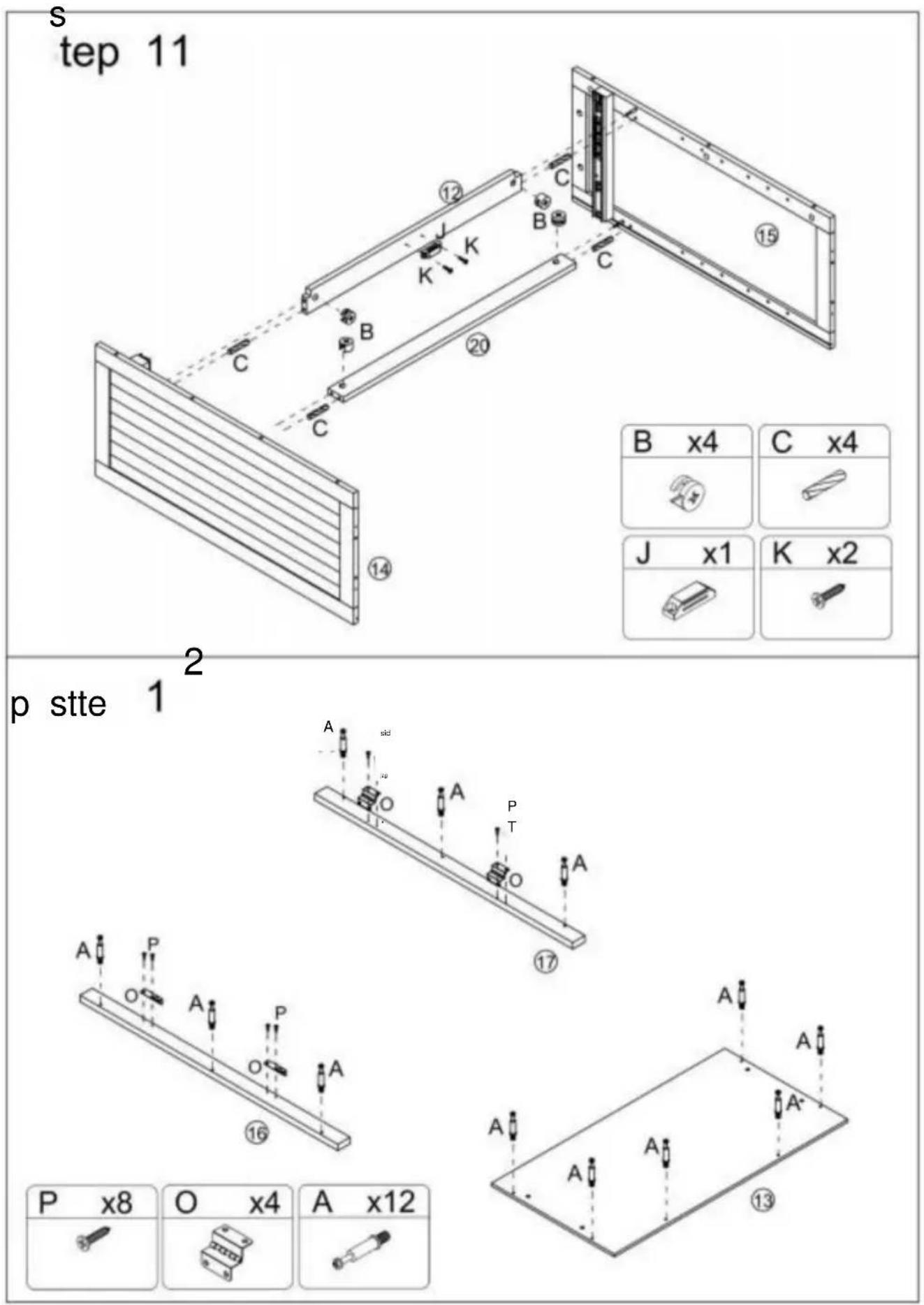
| B x4 | C x4 |
| J x1 | K x2 |
| J x1 | K x2 |
| |
Steg 13
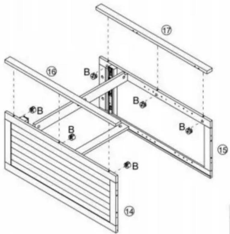
text_image
Technical diagram of a structural frame assembly with numbered components and labeled parts B and flanges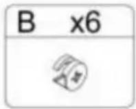
Step 14
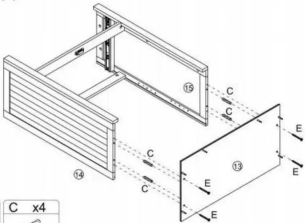
text_image
C x4 ⑭ ⑮ ⑯ ⑰ ⑱ ⑲ ⑳ ⑴ C C C E E E E
Steg 15
text_image
Technical diagram of a mechanical device with numbered components and directional arrows indicating assembly or movement.Steg 17
natural_image
Isometric line drawing of a two-compartment electronic device with internal components and mounting holes (no text or symbols)
Steg 18
text_image
Technical diagram of a multi-level cabinet with labeled R-R and directional arrows, including an inset showing a switch labeled L and switch K.K x16] IL\~x16j R x8]

1 j

Step 19
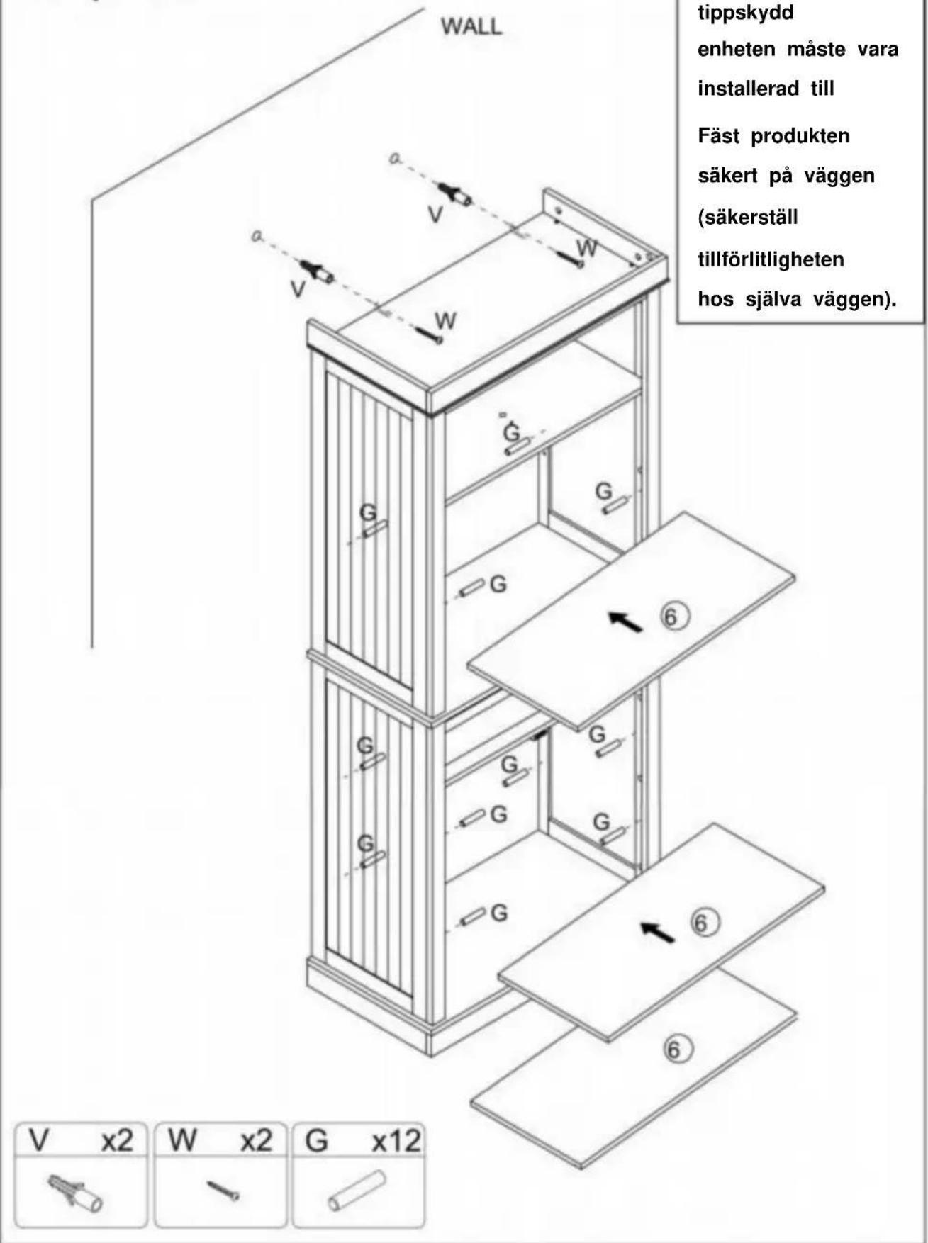
text_image
Technical diagram of a multi-level cabinet with labeled doors, doors, and directional arrows indicating assembly or movement.IH 1x4] sid x4l rp\~x2oi [Q^4]

text_image
1 9 1Steg 21
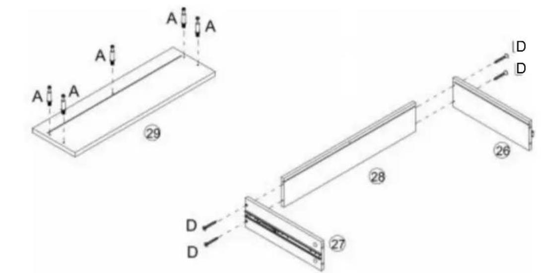
text_image
A A A A 29 28 26 D D 27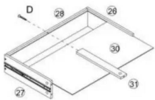
text_image
D 28 26 30 31 27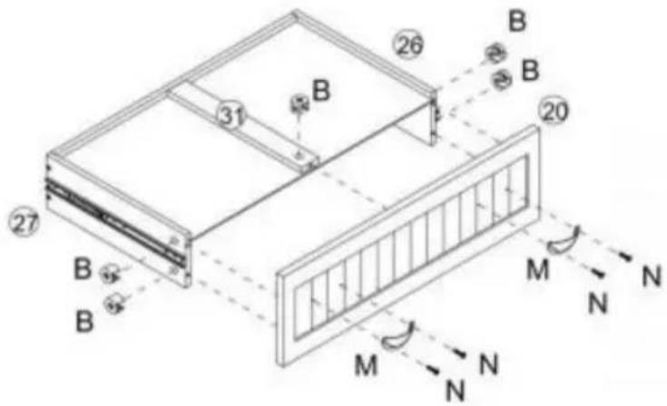
text_image
Technical diagram of a structural frame with labeled components and directional arrows indicating force or movement.| A x5 | D x5 | B x5 | M x2 | N x4 |
Steg 22
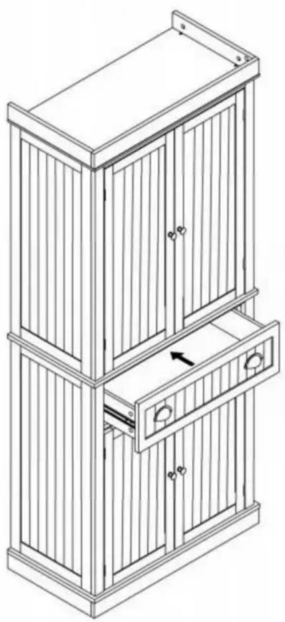
natural_image
Line drawing of a two-tiered wooden cabinet with vertical slats and doorways (no text or symbols)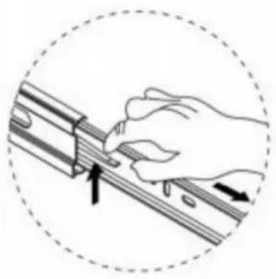
natural_image
Illustration of a hand using a tool to adjust or install a mechanical component, enclosed in a dashed circle (no text or symbols)www.vevor.com/support