
ZXDC12V-1.6KW-D-4L - Hydraulic unit Vevor - Free user manual and instructions
Find the device manual for free ZXDC12V-1.6KW-D-4L Vevor in PDF.
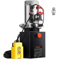


| Product type | Hydraulic unit (power pack) |
| Brand | Vevor |
| Model | ZXDC12V-1.6KW-D-4L |
| Power supply voltage | 12 V DC |
| Motor power | 1.6 kW |
| Oil tank capacity | 4 L (model -4L) |
| Maximum pressure | 16 to 20 MPa |
| Flow rate | 1.1 mL/h (per manual) |
| Rotation speed | 2600 rpm |
| Tank material | Steel or plastic |
| Tank color | White or black |
| Pump type | High pressure gear pump |
| Protection class | III |
| Current | Direct current (DC) |
| Operating mode | Duty cycle S3: 30 s on, 270 s off, max 180 s continuous |
| Main uses | Small dump trucks, hydraulic winches |
| Recommended oil type | Anti-wear hydraulic oil ISO VG46 (<50°C) or VG68 (>50°C) |
| Oil viscosity | 22-46 mm²/s at 50°C |
| Operating temperature | -10 to 80°C |
| Power wire cross-section | Copper wire 20-25 mm² |
| Included accessories | Handheld remote control, additional SAE#6 connector |
| Maintenance | Oil change after first 100h, then annually or after 1500h |
Frequently Asked Questions - ZXDC12V-1.6KW-D-4L Vevor
User questions about ZXDC12V-1.6KW-D-4L Vevor
0 question about this device. Answer the ones you know or ask your own.
Ask a new question about this device
Download the instructions for your Hydraulic unit in PDF format for free! Find your manual ZXDC12V-1.6KW-D-4L - Vevor and take your electronic device back in hand. On this page are published all the documents necessary for the use of your device. ZXDC12V-1.6KW-D-4L by Vevor.
USER MANUAL ZXDC12V-1.6KW-D-4L Vevor
Technical Support and E-Warranty Certificate www.vevor.com/support
HYDRAULIC POWER UNIT
SERIES:ZXDC12V-1.6KW-D-_X L
(TIPS: X IS 3/4/4.5/6/7/8/10/12/13/14/15/20)
We continue to be committed to provide you tools with competitive price. "Save Half", "Half Price" or any other similar expressions used by us only represent of savings you might benefit from buying certain tools with us compared top brands and doses not necessarily mean to cover all categories of tools offered are kindly reminded to verify carefully when you are placing an order with us actually saving half in comparison with the top major brands.
VEVOR®
TOUGH TOOLS, HALF PRICE
HYDRAULIC
POWER UNIT
SERIES:ZXDC12V-1.6KW-D-_X L
NEED HELP? CONTACT US!
Have product questions? Need technical support? Please feel fr contact us:
Technical Support and E-Warranty Certificate www.vevor.com/support
This is the original instruction, please read all manual instruction carefully before operating. VEVOR reserves a clear interpretation user manual. The appearance of the product shall be subject to product you received. Please forgive us that we won't inform you there are any technology or software updates on our product.
| Warning- To reduce the risk of injury, users must read the instructions manual carefully. | |
 | CORRECT DISPOSALThis product is subject to the provision of European Directive 2012/19/EC. The symbol showing a wheelie bin crossed through indicates that the product requires separate refuse collection European Union. This applies to the product and all access marked with this symbol. Products marked as such may not discarded with normal domestic waste but must be taken to collection point for recycling electrical and electronic devices. |
 | This product is of protection class III. |
| DC | Direct current |
INSTRUCTIONS
The hydraulic power unit integrates a high-pressure gear pump, a DC multi-purpose integrated block, various hydraulic valves, an oil tank, and components organically. It is a typical hydraulic circuit for power up and power down. The second relief valve of the system controls the downward pressure, and the pressure-compensated flow valve automatically adjusts the falling speed. This product is widely used in dump trucks, hydraulic winches, etc.
CAUTION
- The battery power must be sufficient, with a current of 200A and voltage to match the machine.
- When the vehicle hydraulic pump is an S3 working system, it is not for continuous operation: 30 seconds to start, 270 seconds to stop. The maximum working time is 180 seconds, with an intermittent 360 seconds. Continuous working time that is too long will cause motor short circuit or damage.
- When the hydraulic power unit produced by our Company leaves the
factory, the system pressure has been set. If changes are needed, users can adjust the system pressure by themselves through a pressure regulator knob according to the situation. Still, it cannot exceed the nominal pressure (16 MPa) of the system.
- Check the connection of the motor and electromagnetic valve carefully, and it is strictly forbidden to make a virtual connection.
- During the first installation and debugging, pay attention to keeping the oil level inside the oil tank. After a working cycle, the oil tank should be filled, but it cannot be overfilled.
- The motor terminal box should be waterproof and moisture-proof. When connecting for the first time, inch the motor to carefully check the direction of the motor. From the rear end of the motor, the direction is counterclockwise. It is absolutely forbidden to reverse the rotation of the motor and idle without oil.
- When the oil tank is filled, the hydraulic oil must be filtered with an accuracy of no less than 25 μm.
- The power unit cannot filter out impurities inside the hydraulic cylinder. Therefore, the inside of the hydraulic cylinder must be clean to avoid the failure of the valve. The tubing must also be clean.
SAVE THESE INSTRUCTIONS
TECHNICAL PARAMETERS
| Action | Single |
| voltage | 12 V |
| Reservoir Capacity | 3/4/4.5/6/7/8/10/12/13/14/15/20 Quart |
| Power | 1.6 KW |
| Rotating Speed | 2600 RPM |
| Pressure | 16~20 MPa |
| Traffic | 1.1 mL/r |
| Tank Material | Steel or Plastic |
| Tank Color | White or Black |
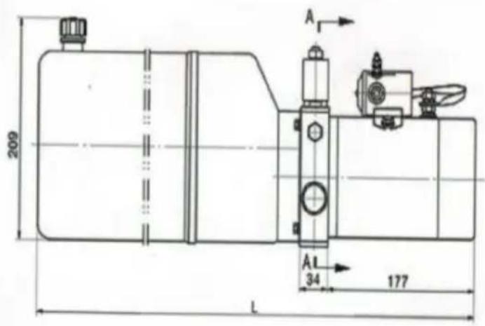
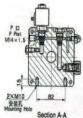
PARTS ILLUSTRATION
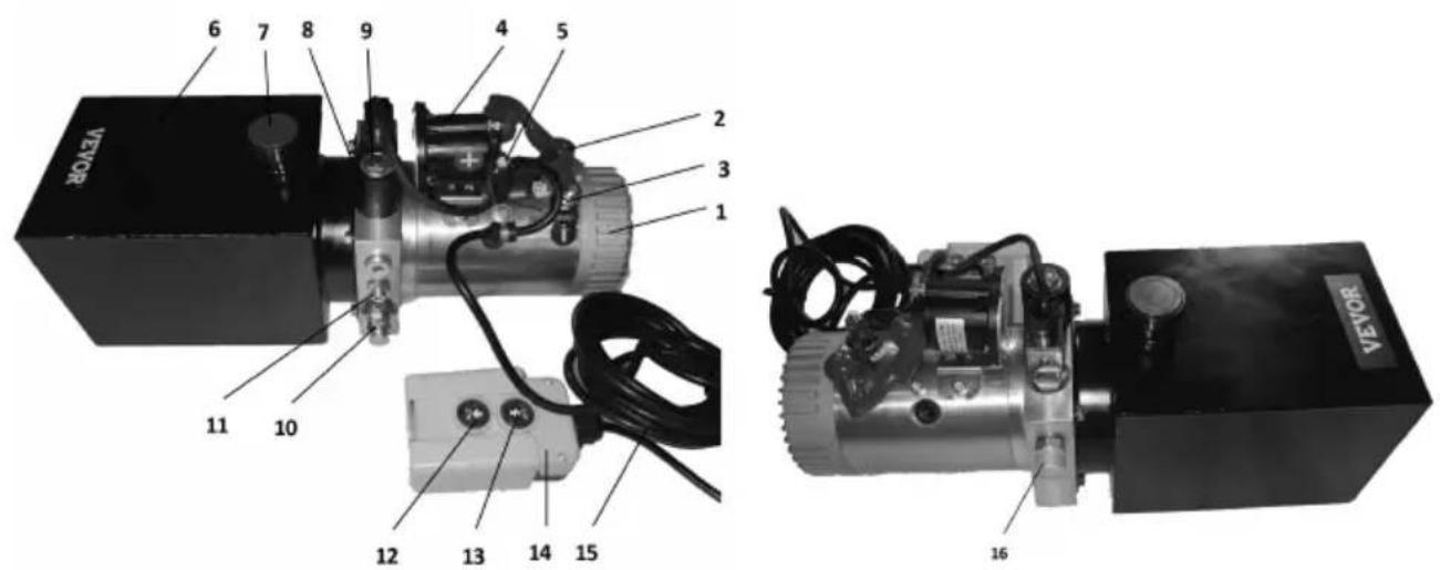
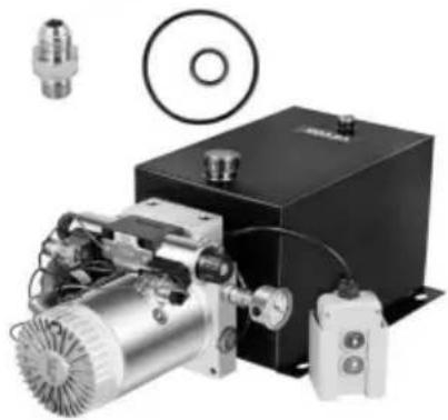
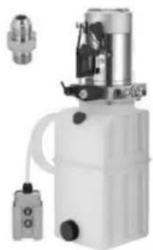
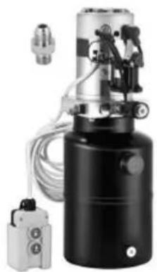
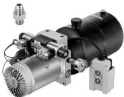
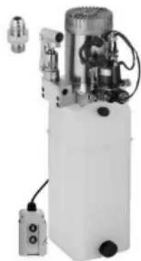
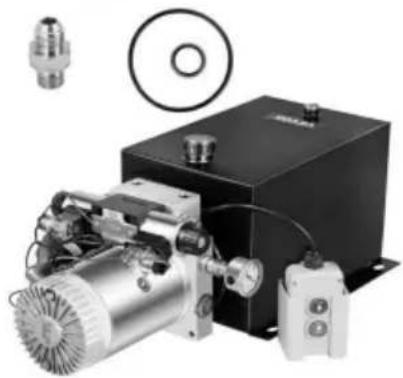
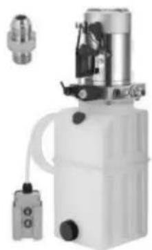
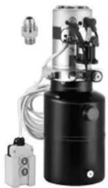
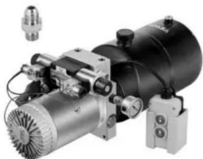
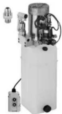
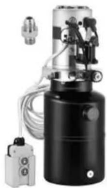
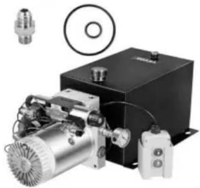
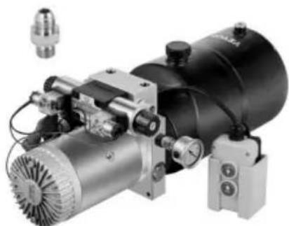
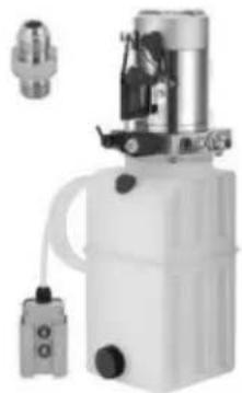
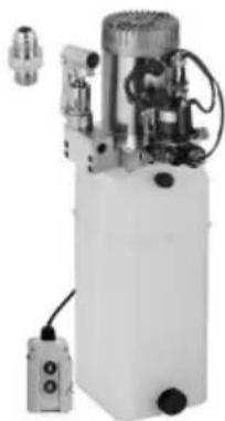
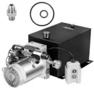
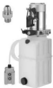
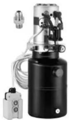
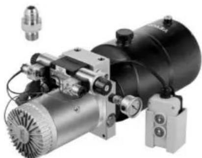
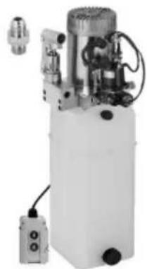
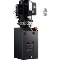
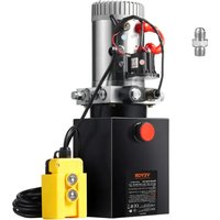
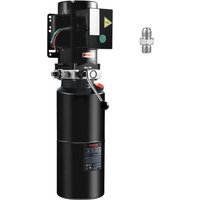
The Hydraulic Power Unit has been fully assembled. It comes with a hand-held remote control and 1 additional SAE#6 connector for replacement. The whole power unit is easy to wire and easy to operate.
| Part List | |
| 1 Electronic motor | 9 Normally closed solenoid valve |
| 2 The positive pole of the electronic m | 10 Overflow valve |
| 3 The negative pole of the electronic r | 11 Throttle valve |
| 4 Relay | 12 Down button |
| 5 The positive pole of the relay | 13 Up button |
| 6 Reservoir | 14 Control box |
| 7 Reservoir filler | 15 Control wire |
| 8 Electromagnetic coil A | 16 Oil outlet |
WORKING PRINCIPLE AND WIRING METHOD
- Fill hydraulic oil from the reservoir filler until it is 3 cm below the upper surface of the reservoir.
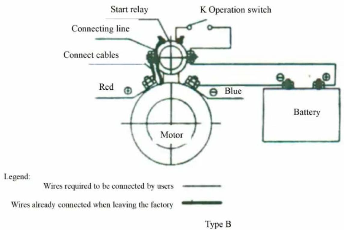
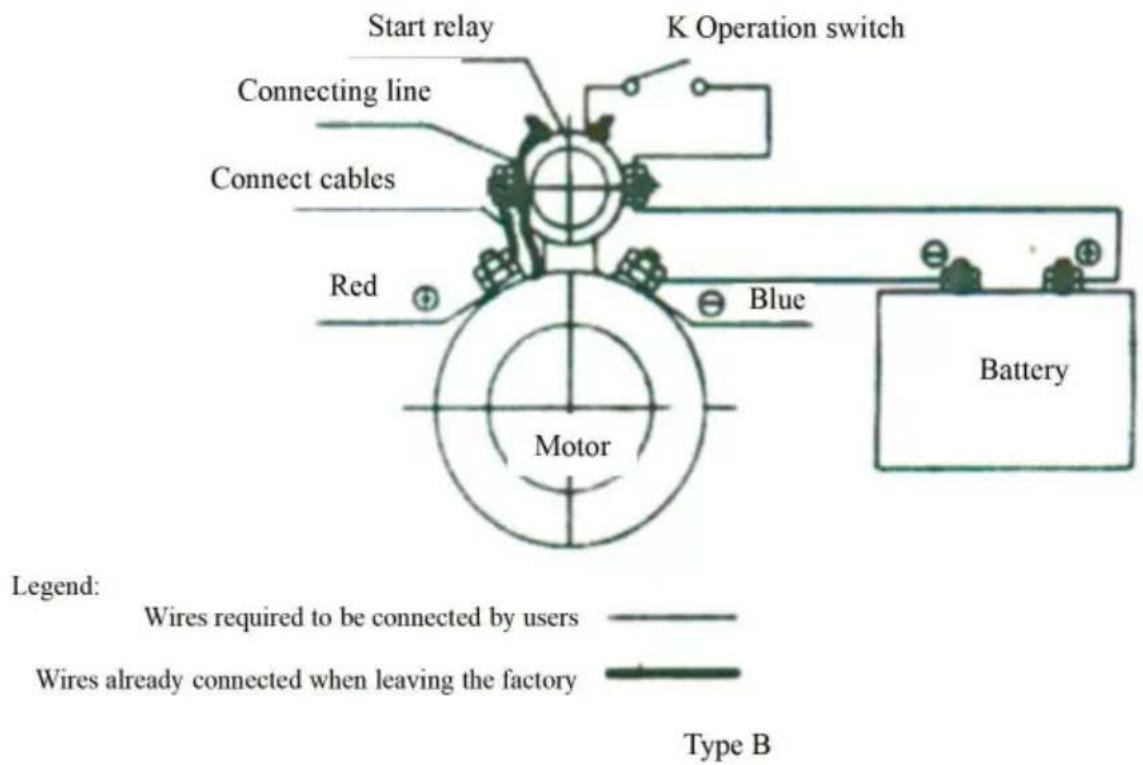
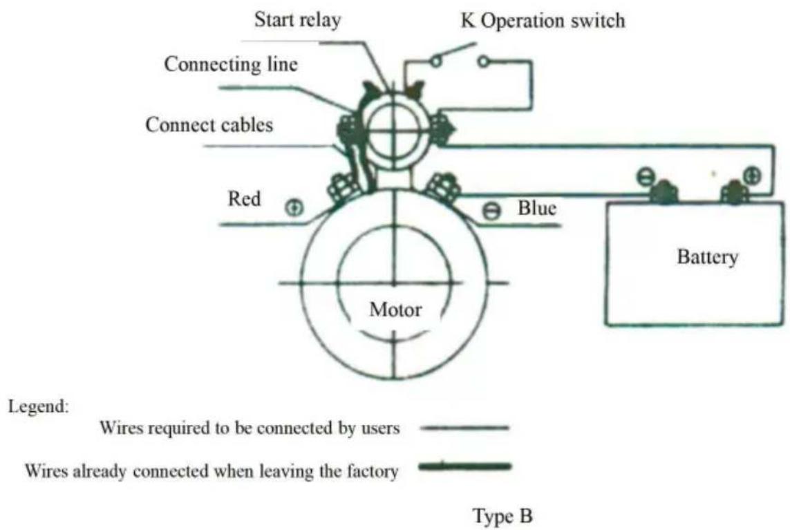
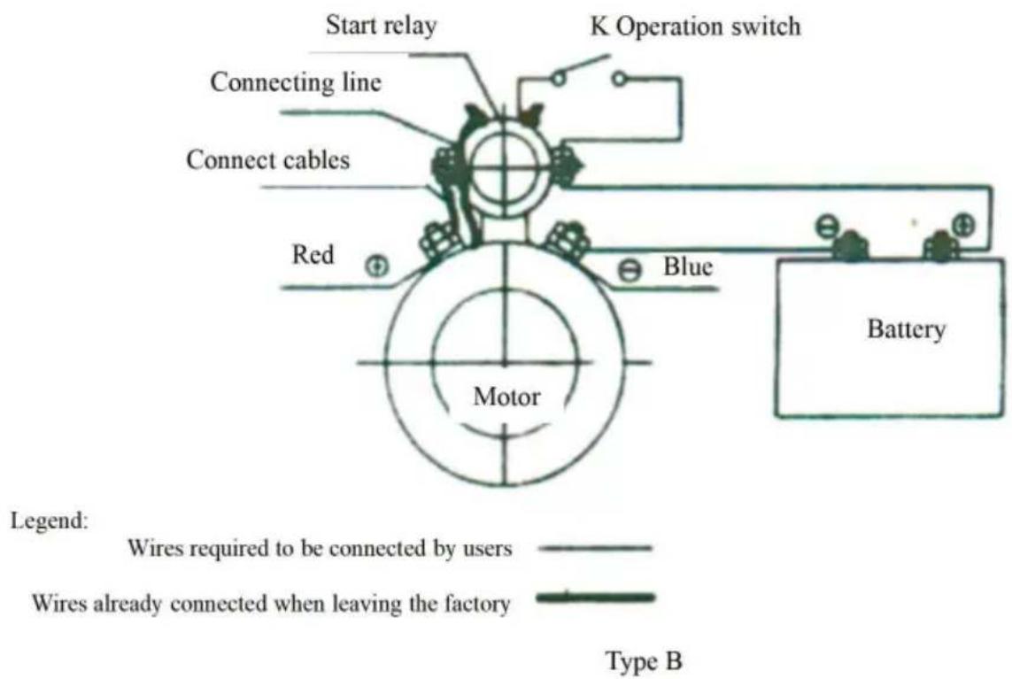
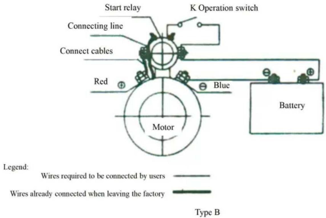
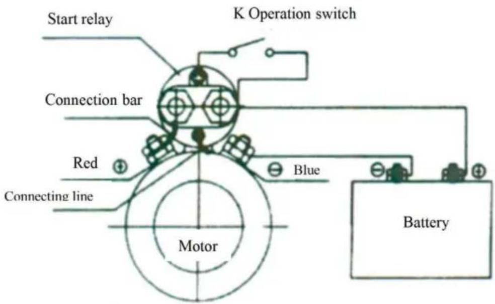
- Connect the positive pole of the power supply to the
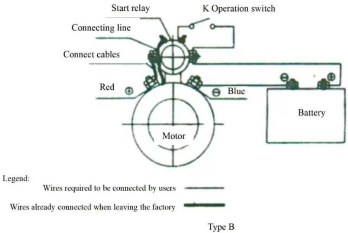
positive pole of the relay, and the negative pole of the power supply to the negative pole of the electric motor. The power supply wire must be copper wire with a cross-sectional area of 20 to 25 mm².
- Connect the power supply correctly, then install the oil pipelines. Press the Up button to start the motor. The motor drives the oil pump to generate pressure and discharge oil. When the Up button is released, the motor should stop working.
- At the end of the hydraulic cylinder's travel, press the Down button for oil return. The motor does not need to work during this process; the indicator light of the electromagnetic coil will light up, and the coil generates magnetic force to push the electromagnetic valve. This allows the oil to return and the hydraulic cylinder to return to its original position.
- When the motor is working to discharge oil and generate pressure, the electromagnetic coil must be powered off, and its indicator light should not light up.
COMMON FAILURES AND TROUBLESHOOTING
- Does not rise (advance) or rises (advances) unstably.
a. Oil level in the tank is too low; add oil to the specified level. b. The hydraulic power unit should use anti-wear hydraulic oil with a kinematic viscosity of 22-46 mm²/s (at 50°C). ISO VG46 is recommended when the oil temperature is below 50°C, while ISO VG68 is recommended when the oil temperature is above 50°C. The added oil should be filtered with a filtration accuracy of 30 μm. The oil volume should be based on the effective capacity of the oil tank. The oil temperature is usually between -10°C and 80°C; for extremely cold areas, low-temperature hydraulic oil such as ISO VG32 should be used. These measures can effectively prolong the service life of the hydraulic system and components and improve the stability and reliability of the hydraulic power unit.
c. Oil filter screen is blocked; wash or replace the filter screen.
d. Suction pipe is unsealed or leaking; check for leaks or unsealed areas, and repair or replace the pipe.
e. Electromagnetic valve or hand valve is not closed; wash the electromagnetic valve and hand valve, or replace the oil.
- Does not drop or drops unstably.
a. Electromagnetic valve or hand valve filter screen is blocked; clean the screen and the electromagnetic valve.
b. Blocked throttle valve, adjust the throttle valve.
- Do not pressurize
a. Unsealed check valve, wash the check valve or replace the oil seal.
SIMPLE COMMISSIONING DIAGRAM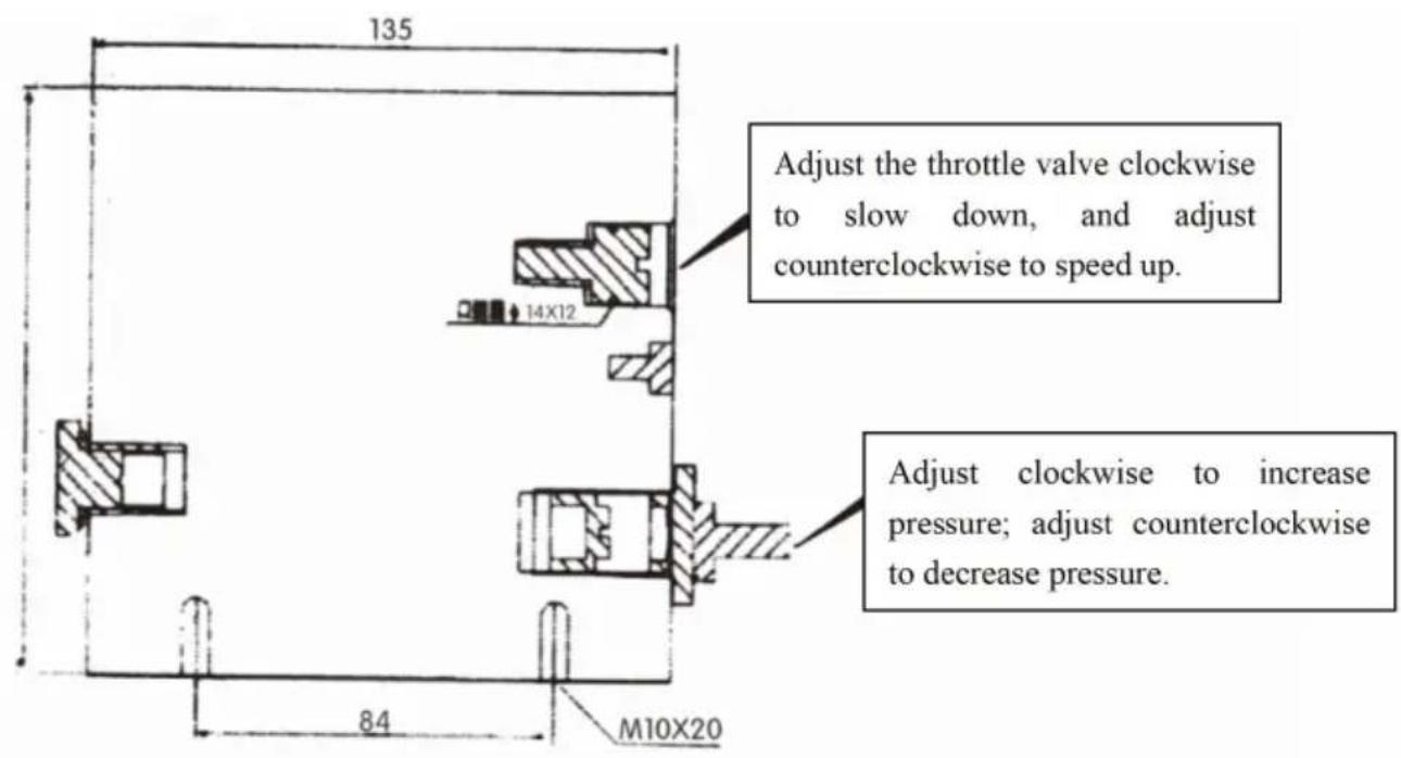
SCHEMATIC DIAGRAM
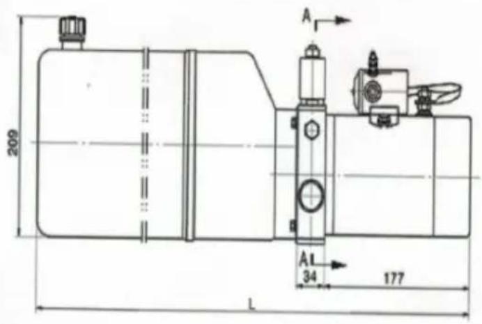
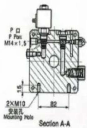
![graph TD A["P"] --> B["Valve"] B --> C["Actuator"] C --> D["M"] D --> E["Z"] E --> F["Valve"] F --> G["Actuator"] G --> H["Z"] H --> I["Valve"] I --> J["Actuator"] J --> K["Z"] K --> L["Valve"] L --> M["Actuator"] M --> N["Z"] N --> O["Valve"] O --> P["Actuator"] P --> Q["Z"] Q --> R["Valve"] R -->…](/content/2026/04/737186/images/ba50cefcd393802fc6342cf4e7c7cb8e6e4878908e9272be1f6959cc6a49b143.jpg)
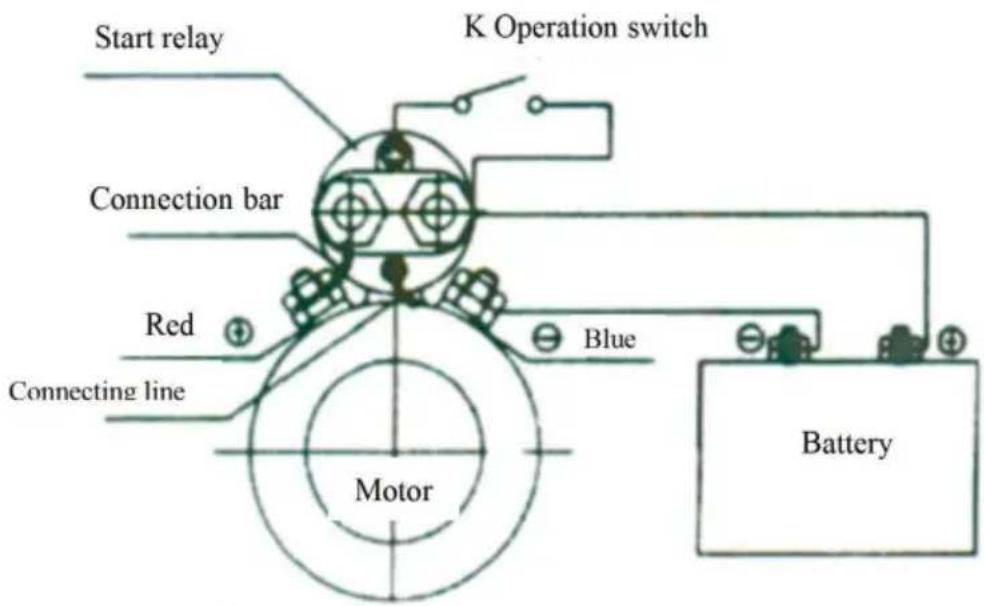
DC MOTOR ELECTRIC WIRING DIAGRAM
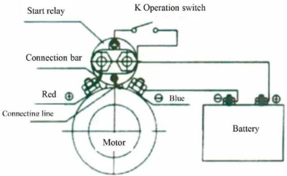
Legend:
Wires required to be connected by users

Wires already connected when leaving the factory
Type A
MAINTENANCE
- Actuators and pipelines should be kept clean to prevent the introduction of foreign material into the system.
- The reservoir should be adequately filled with oil. Proper refilling is needed after certain working cycles. It may damage the oil pump and enclosure if the oil pump sucks air.
- The hydraulic oil should be replaced upon working for 100 hours after the initial filling. Subsequently, the hydraulic oil should be replaced once per year or at about 1500 working hours.
- The viscosity of the hydraulic oil should be 225.46 mm
- High-viscosity hydraulic oil should be used in high-temperature work environments, while low-viscosity hydraulic oil should be used in low-temperature environments.
VEVOR®
TOUGH TOOLS, HALF PRICE
Technical Support and E-Warranty Certificate www.vevor.com/support
VEVOR®
TOUGH TOOLS, HALF PRICE
NEED HELP? CONTACT US!
SCHEMATIC
![graph TD A["P"] --> B["Valve"] B --> C["Actuator"] C --> D["M"] D --> E["Pressure Gauge"] E --> F["X"] F --> G["Decision Point"] G --> H["Valve"] H --> I["Actuator"] I --> J["M"] J --> K["Pressure Gauge"] K --> L["X"] L --> M["Valve"] M --> N["Actuator"] N --> O["P"]](/content/2026/04/737186/images/2ff11a7931577242df10a2deb68318efcbf293e6cdfea2fd00c6fe9a59e8fe16.jpg)
Legend: Wires required to be connected by users
Wires already connected when leaving the factory Type A
MAINTENANCE
Legend:
Wires required to be connected by users

Wires already connected when leaving the factory
Type A
MAINTENANCE
www.vevor.com/support
VEVOR®
TOUGH TOOLS, HALF PRICE
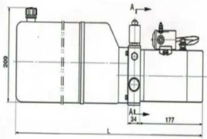
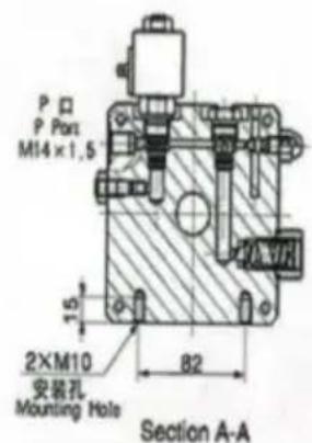
SCHEMATIC DIAGRAM
![graph TD A["P"] --> B["Valve"] B --> C["Actuator"] C --> D["M"] D --> E["Z"] E --> F["Valve"] F --> G["Actuator"] G --> H["Z"] H --> I["Valve"] I --> J["Actuator"] J --> K["Z"] K --> L["Valve"] L --> M["Actuator"] M --> N["Z"] N --> O["Valve"] O --> P["Actuator"] P --> Q["Z"] Q --> R["Valve"] R -->…](/content/2026/04/737186/images/aadba149b1b81babcc15bfd761b3c6ba9fd9c2d7322219bfb355f7100d0e0ed9.jpg)
Legend:
Wires required to be connected by users

Wires already connected when leaving the factory
Type A
MAINTENANCE
SCHEMATIC DIAGRAM
![graph TD A["P"] --> B["Valve"] B --> C["Actuator"] C --> D["M"] D --> E["Z"] E --> F["Valve"] F --> G["Actuator"] G --> H["Z"] H --> I["Valve"] I --> J["Actuator"] J --> K["M"] K --> L["Z"] L --> M["Valve"] M --> N["Actuator"] N --> O["Z"] O --> P["Valve"] P --> Q["Actuator"] Q --> R["M"] R --> S["Z…](/content/2026/04/737186/images/a680781185d9bb8f3a67a377e1753bf3415fde5b9dd8cbe9e26b5da8ac18021e.jpg)
Legend: Wires required to be connected by users
Wires already connected when leaving the factory Type A
MAINTENANCE
NEED HELP? CONTACT US!
SCHEMAT SCHEMATU
![graph TD A["P"] --> B["Valve"] B --> C["Actuator"] C --> D["M"] D --> E["Z"] E --> F["Valve"] F --> G["Actuator"] G --> H["Z"] H --> I["Valve"] I --> J["Actuator"] J --> K["M"] K --> L["Z"] L --> M["Valve"] M --> N["Actuator"] N --> O["Z"] O --> P["Valve"] P --> Q["Actuator"] Q --> R["M"] R --> S["Z…](/content/2026/04/737186/images/043e6f9861142338439560bf33d7b616c7b1a227dae0ffac8d72983c13c47732.jpg)
SCHEMAT PODŁĄCZENIA ELEKTRYCZNEGO SILNIKA PRĄDU STĄŁEGO
Legend:
Wires required to be connected by users

Wires already connected when leaving the factory
Type A
KONSERWACJA
HULP NODIG? NEEM CONTACT MET ONS OP!
WERKINGSPRINCIPE EN BEDRADINGSMETHODE
SCHEMATISCH DIAGRAM
![graph TD A["P"] --> B["Valve"] B --> C["Actuator"] C --> D["M"] D --> E["Z"] E --> F["Valve"] F --> G["Actuator"] G --> H["Z"] H --> I["Valve"] I --> J["Actuator"] J --> K["Z"] K --> L["Valve"] L --> M["Actuator"] M --> N["Z"] N --> O["Valve"] O --> P["Actuator"] P --> Q["Z"] Q --> R["Valve"] R -->…](/content/2026/04/737186/images/8739dca4cdee57e8295abd4779ccec2f87c1f82e564fb95d2e7c79e17382834f.jpg)
ELEKTRISCH BEDRADINGSSCHEMA DC-MOTOR
Legend:
Wires required to be connected by users

Wires already connected when leaving the factory
Type A
MAINTENANCE
WORKING PRINCIPLE AND DRESSING METHOD
SCHEMATIC DIAGRAM
![graph TD A["P"] --> B["Valve"] B --> C["Actuator"] C --> D["M"] D --> E["Z"] E --> F["Valve"] F --> G["Actuator"] G --> H["Z"] H --> I["Valve"] I --> J["Actuator"] J --> K["Z"] K --> L["Valve"] L --> M["Actuator"] M --> N["Z"] N --> O["Valve"] O --> P["Actuator"] P --> Q["Z"] Q --> R["Valve"] R -->…](/content/2026/04/737186/images/a47ce426e542732e6563149b75dad75e6b3be81f257aea4b112e392f2ec1630e.jpg)
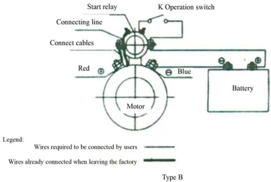
DC MOTOR ELECTRICAL WIRING DIAGRAM
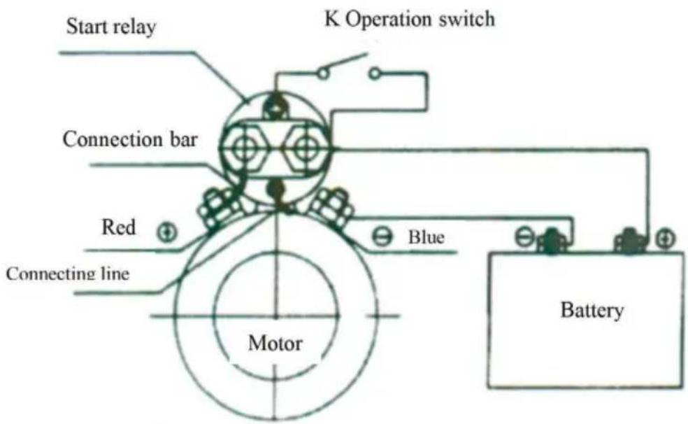
Legend:
Wires required to be connected by users

Wires already connected when leaving the factory
Type A
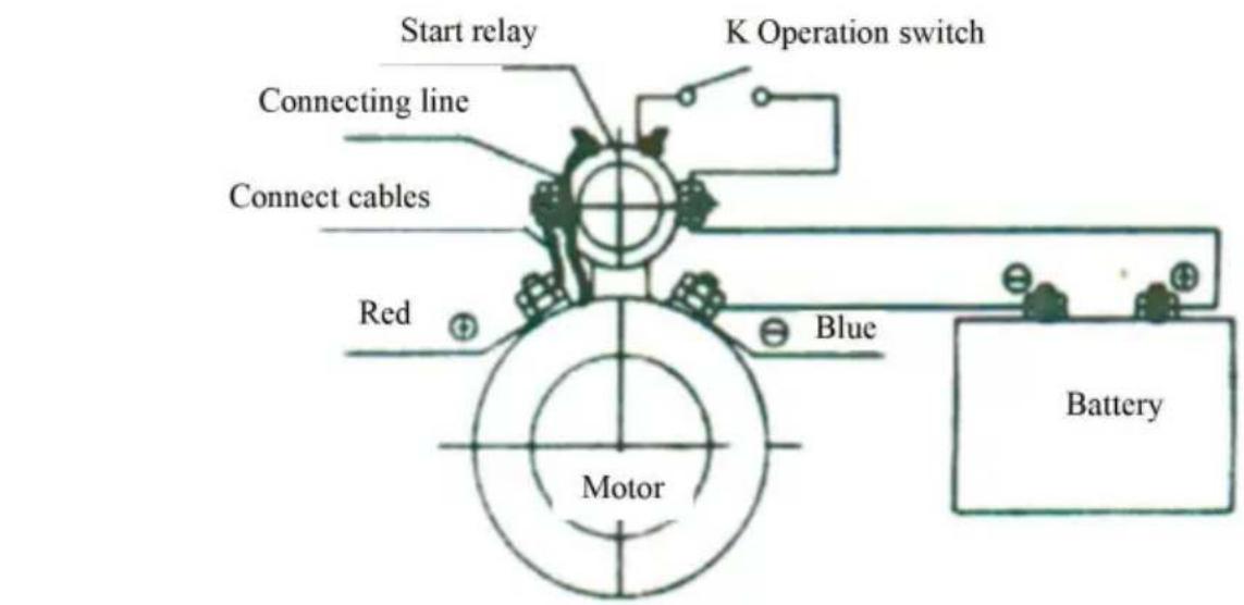

Type B
MAINTENANCE
www.vevor.com/support
- HYDRAULIC POWER UNIT
- VEVOR®
- HYDRAULIC
- POWER UNIT
- NEED HELP? CONTACT US
- INSTRUCTIONS
- CAUTION
- SAVE THESE INSTRUCTIONS
- PARTS ILLUSTRATION
- WORKING PRINCIPLE AND WIRING METHOD
- COMMON FAILURES AND TROUBLESHOOTING
- SCHEMATIC DIAGRAM
- DC MOTOR ELECTRIC WIRING DIAGRAM
- MAINTENANCE
- TOUGH TOOLS, HALF PRICE
- SCHEMATIC
- SCHEMAT SCHEMATU
- SCHEMAT PODŁĄCZENIA ELEKTRYCZNEGO SILNIKA PRĄDU STĄŁEGO
- KONSERWACJA
- HULP NODIG? NEEM CONTACT MET ONS OP
- WERKINGSPRINCIPE EN BEDRADINGSMETHODE
- SCHEMATISCH DIAGRAM
- ELEKTRISCH BEDRADINGSSCHEMA DC-MOTOR
- WORKING PRINCIPLE AND DRESSING METHOD
- DC MOTOR ELECTRICAL WIRING DIAGRAM
Brand : Vevor
Model : ZXDC12V-1.6KW-D-4L
Category : Hydraulic unit