
ZD200 - Monitor Stand Vevor - Free user manual and instructions
Find the device manual for free ZD200 Vevor in PDF.

| Product Type | Desktop Monitor Stand |
| Brand | Vevor |
| Model | ZD200 |
| Product Dimensions | 1020 x 110 x 500 mm |
| Safe Load Capacity (Total) | 24 kg (52.9 lb) |
| Safe Load Capacity (per arm) | 12 kg (26.4 lb) |
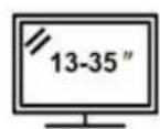
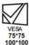
| Compatible VESA Standard | 75 x 75 mm, 100 x 100 mm |
| Main Material | Steel |
| Number of Arms | 2 |
| Mounting Type | Clamp or Drill Mounting |
| Height Adjustment | Yes, via central column |
| Screen Rotation | Yes, swivel and tilt |
| Power Supply | None (mechanical stand) |
| Intended Use | Indoor only |
| Package Contents | Stand, mounting screws, Allen keys |
| Assembly Instructions | Included (two methods: clamp or drill) |
| Maintenance | Clean with a soft, dry cloth |
| Warranty | Electronic warranty via www.vevor.com/support |
| Safety | Never exceed maximum load; check desk sturdiness |
| Repairability | Spare parts available on request via technical support |
Frequently Asked Questions - ZD200 Vevor
User questions about ZD200 Vevor
0 question about this device. Answer the ones you know or ask your own.
Ask a new question about this device
Download the instructions for your Monitor Stand in PDF format for free! Find your manual ZD200 - Vevor and take your electronic device back in hand. On this page are published all the documents necessary for the use of your device. ZD200 by Vevor.
USER MANUAL ZD200 Vevor
Technical Support and E-Warranty Certificate www.vevor.com/support
MONITOR DESK MOUNT USER MANUAL
MODEL:ZD200
We continue to be committed to provide you tools with competitive price. "Save Half", "Half Price" or any other similar expressions used by us only represents an estimate of savings you might benefit from buying certain tools with us compared to the major top brands and does not necessarily mean to cover all categories of tools offered by us. You are kindly reminded to verify carefully when you are placing an order with us if you are actually saving half in comparison with the top major brands
VEVOR®
TOUGH TOOLS, HALF PRICE
MONITOR DESK MOUNT
MODEL:ZD200
natural_image
Technical line drawing of a mechanical arm with two articulated arms and a base mount (no text or symbols)
NEED HELP? CONTACT US!
Have product questions? Need technical support? Please feel free to contact us: Technical Support and E-Warranty Certificate www.vevor.com/support
This is the original instruction, please read all manual instructions carefully before operating. VEVOR reserves a clear interpretation of o user manual. The appearance of the product shall be subject to the product you received. Please forgive us that we won't inform you ag there are any technology or software updates on our product.
WARNING:
Read this material before using this product. Failure to do so can re in serious injury.
Assembly precautions
- Assemble only according to these instructions. Improper assembly can create hazards.
- Keep the assembly area clean and well-lit.
- Keep bystanders out of the area during assembly.
- Do not assemble when tired or when under the influence of alcohol, or medication.
- The product capabilities apply to properly and completely assembled products only.
- For additional information regarding the parts listed in the following page please refer to the Assembly Diagram of this manual. Unwrap and separate all parts in a clean work area.
Use precautions
- Use with products heavier than the rated weights indicated may result instability causing possible injury.
- Mounts must be attached as specified in assembly instructions. Improper installation may result in damage or serious personal injury.
- Make sure that the supporting surface will safely support the combined weight of the equipment and all attached hardware and components.
- Use the mounting screws provided and DO NOT OVER TIGHTEN mounting screws.
- This product contains small items that could be a choking hazard if swallowed. Keep these items away from children.
- This product is intended for indoor use only. Using this product outdoor could lead to product failure and personal injury.
SAVE THIS MANUAL
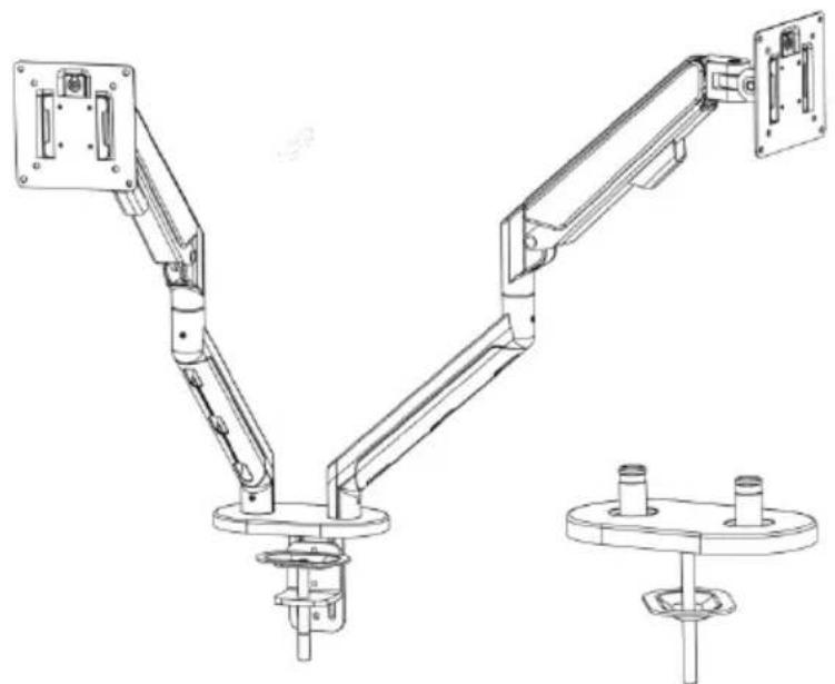
PRODUCT PARAMETER
| Model ZD200 | |
| Safe Loading Weight Total:52.9 | ls Max; Single:26.4 lbs Max |
| VESA 75*75mm, 100*100mm | |
| Product Size 1020*110*500mm |
PARTS LIST
 |  |  |  | 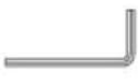 | 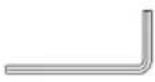 | 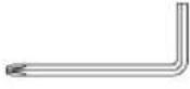 |
| M4×10 (×8)A | M5×10 (×8)B | M6×9 (×3)C | M6×10 (×2)D | 3MM (×1)E | 4MM (×1)F | 5MM (×1)G |
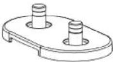 1 (×1) 1 (×1) | 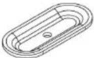 2 (×1) 2 (×1) | 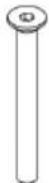 3 (×1) 3 (×1) |  4 (×2) 4 (×2) | 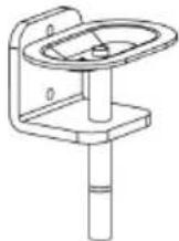 5 (×1) 5 (×1) | ||
 6 (×1) 6 (×1) | 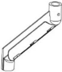 7 (×2) 7 (×2) | 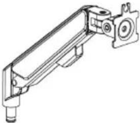 8 (×2) 8 (×2) | 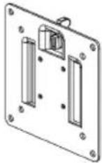 9 (×2) 9 (×2) | 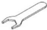 10 (×1) 10 (×1) | ||
 11 (×2) 11 (×2) | 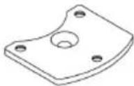 12 (×1) 12 (×1) |  13 (×1) 13 (×1) | ||||
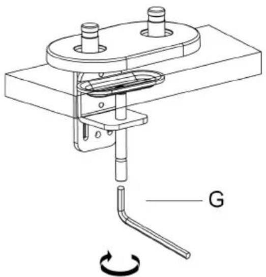
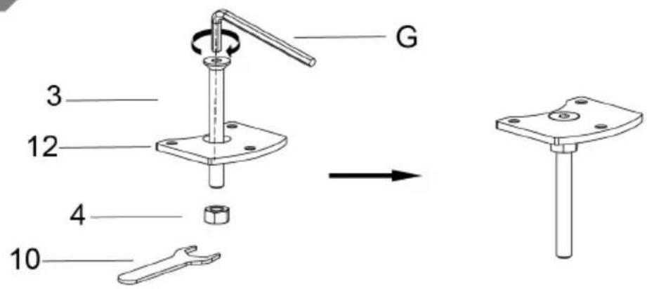
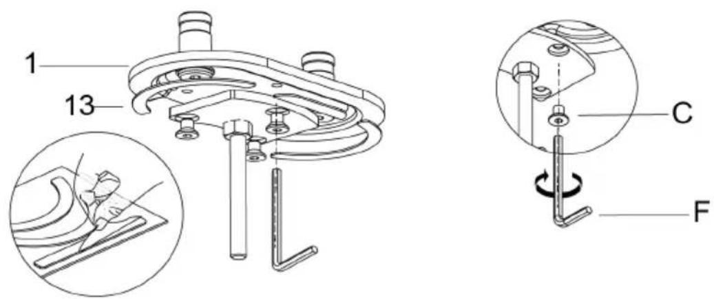
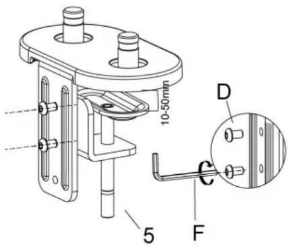
Method 1 ----1a
1a-1
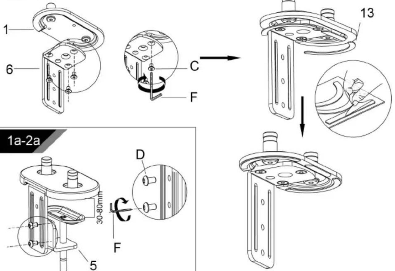
1a-2b
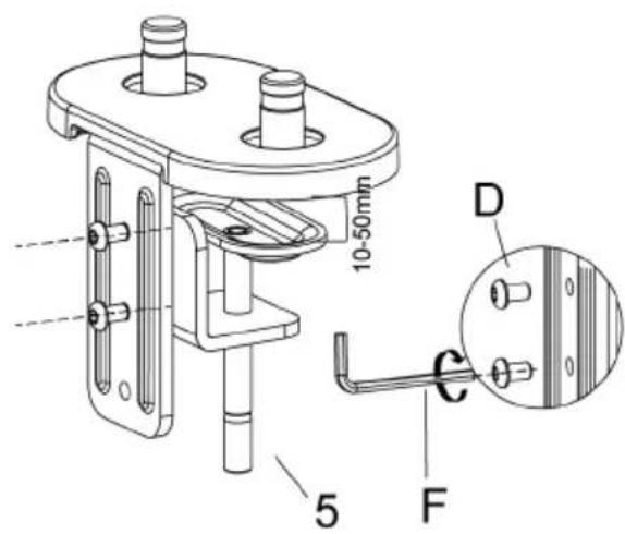
1a-3
natural_image
Technical line drawing of a mechanical assembly with labeled component G and rotational motion indicator (no text or symbols beyond label)Method 2----1b
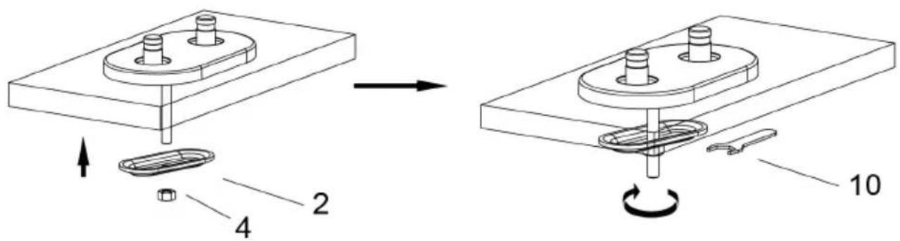
(Desktop has a hole for item 2 to go through)
1b-1
1b-2
2
3
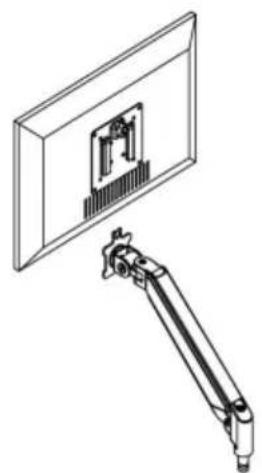
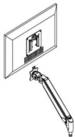
Connect With monitor
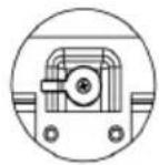
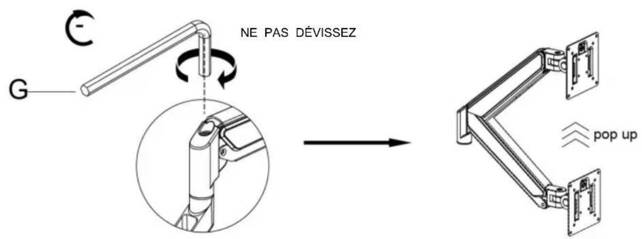
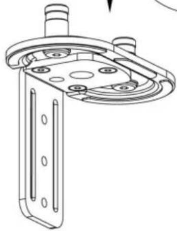
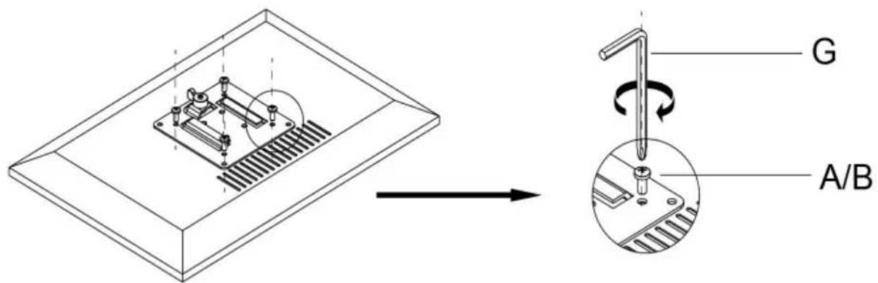
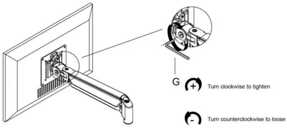
Use a wrench (G) to screw the screws (A/B) into the four holes at the back of the monitor to avoid damaging the moni-tor by over tightening the screws.

4
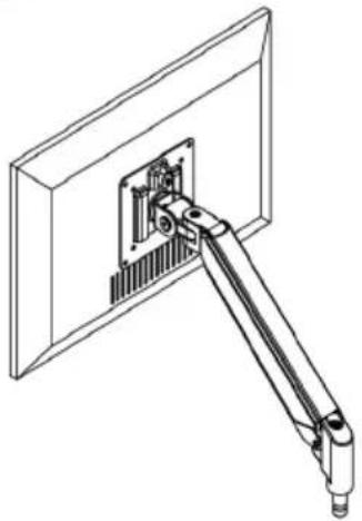
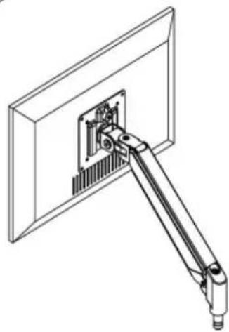
When the display is inserted into the quick release head, make sure the knob is vertical.
After insertion, rotate the knob 90 degrees to the left.

natural_image
Technical line drawing of a mechanical assembly with a mounted bracket and a rectangular component (no text or symbols)
natural_image
Technical line drawing of a mechanical arm assembly mounted on a wall-mounted panel (no text or symbols)5-1
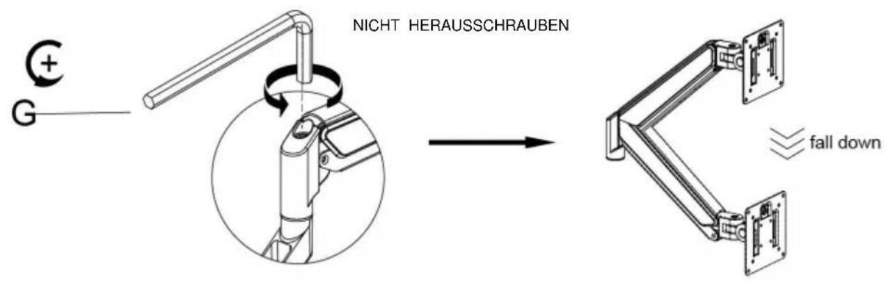
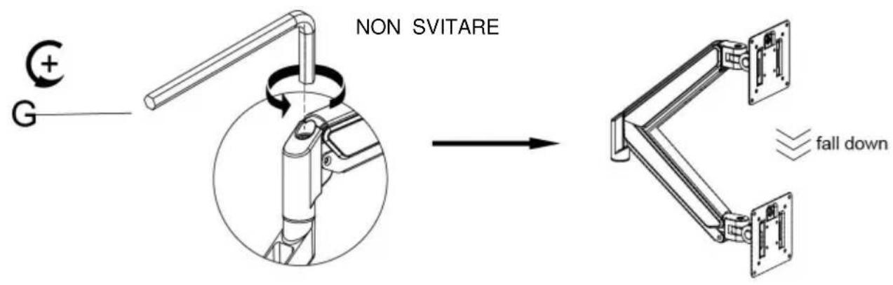
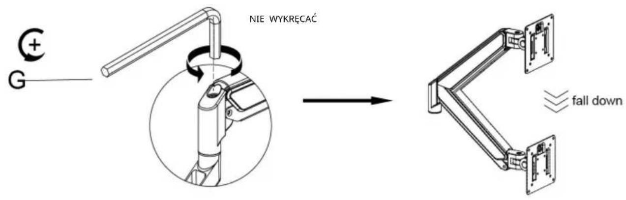
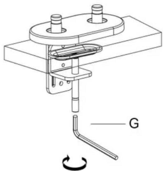
Case 1: Monitor/Arm fall down (after install your monitor)
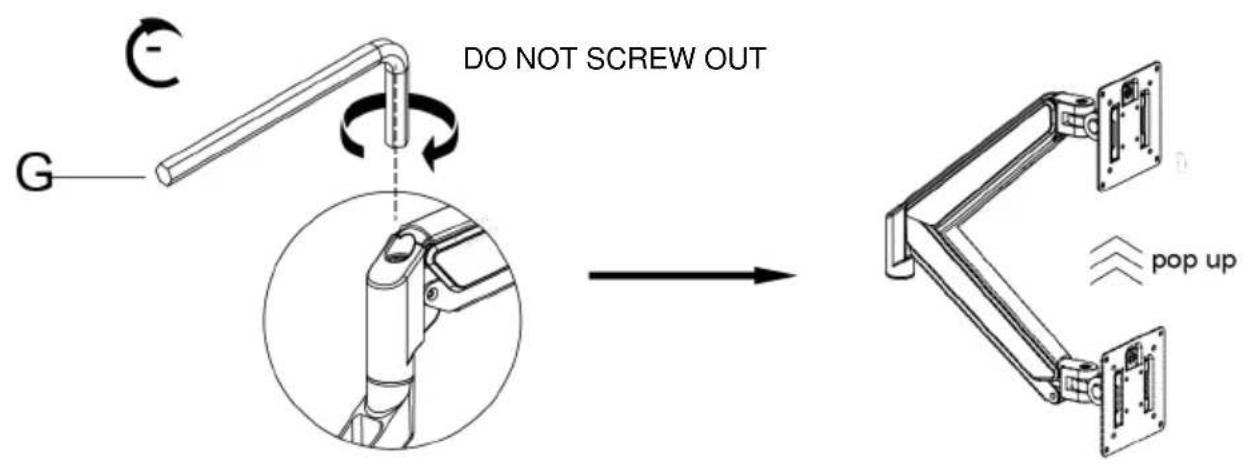
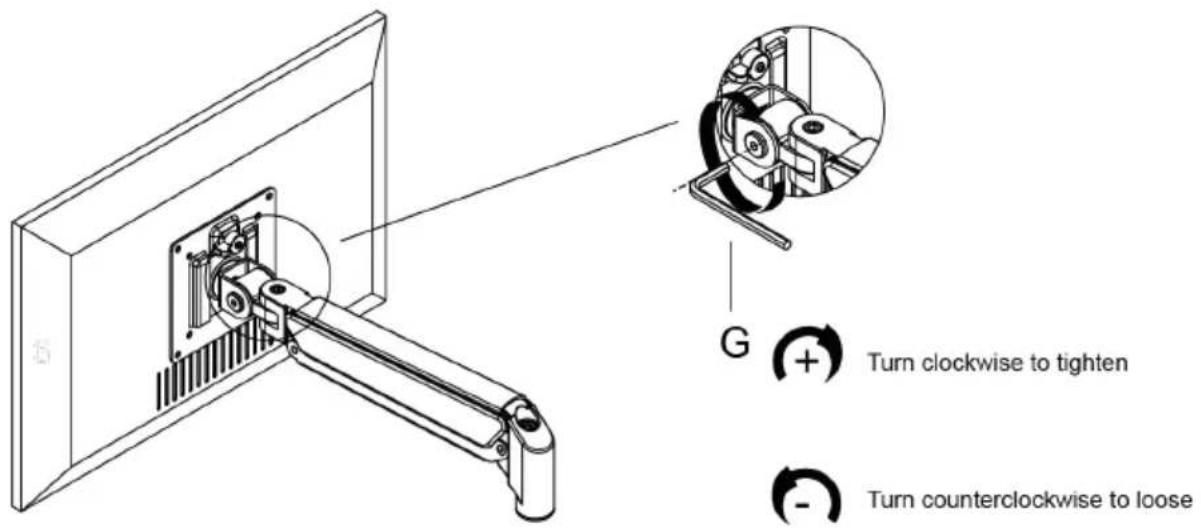
Press the arm to make it keep it in horizontal position and then use the Allen Key to adjust the screw on the arm. Turn counter-clockwise("+ " direction) to increase gas spring tension till can hold the weight of your monitor.
Note: You may need to turn the screw by many circles to tighten the arm.

5-2
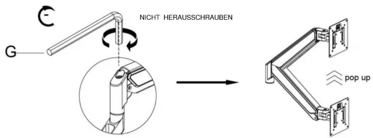
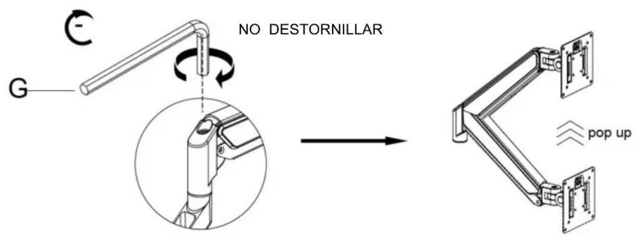
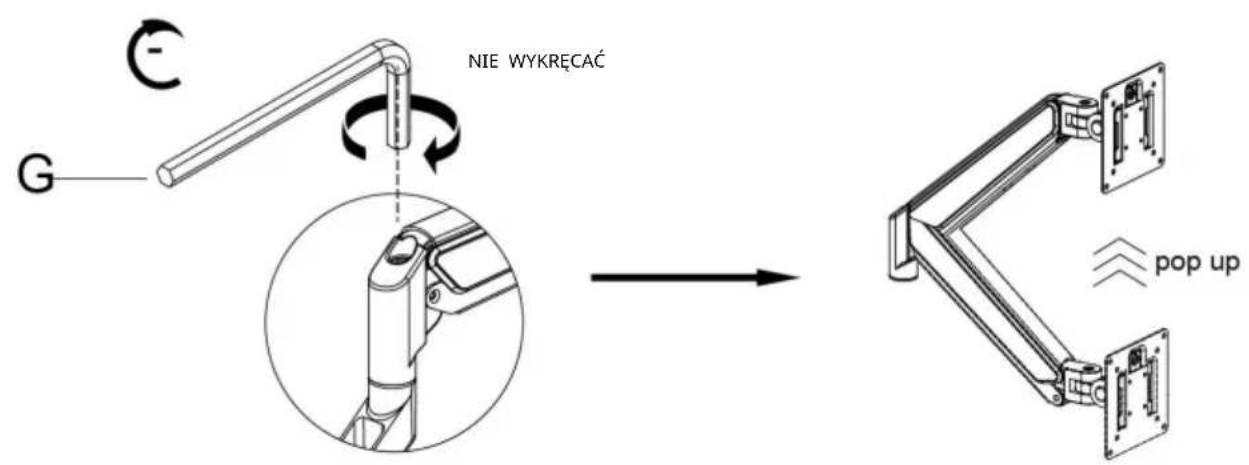
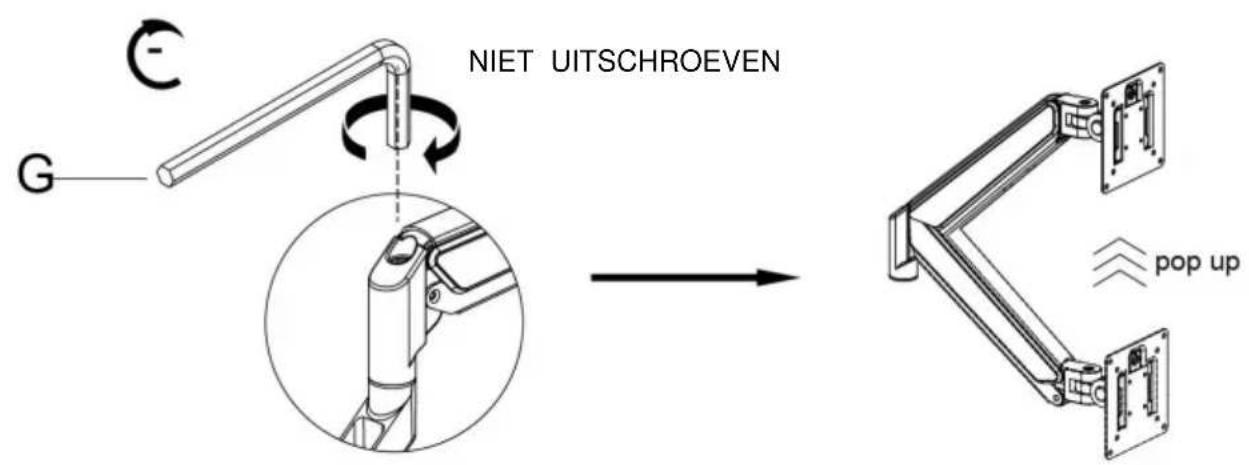
Case 2: Monitor/Arm pops up (after install your monitor)
Press the arm to make it keep it in horizontal position and then use the Allen Key to adjust the screw on the arm. Turn clockwise("- " direction) to reduce gas spring tension till can stay the position needed.
Note: You may need to turn the screw by many circles to tighten the arm.
6
Adjust Flexibility
If you feel the pitching angle too tight or too loose when adjusting the mount, please adjust the Screw
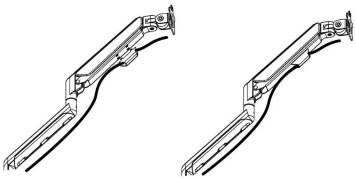
7
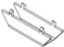
Cable Management

natural_image
Technical line drawing of two mechanical linkage components (no text or symbols)8
Adjustable Instruction

Manufacturer: Shanghaimuxinmuyeyouxiangongsi
Address: Shuangchenglu 803nong11hao1602A-1609shi, baoshanqu, shanghai 200000 CN.
Imported to AUS: SIHAO PTY LTD. 1 ROKEVA STREETEASTWOOD NSW 2122 Australia
Imported to USA: Sanven Technology Ltd. Suite 250, 9166 Anaheim Place, Rancho Cucamonga, CA 91730
E-CrossStu GmbH
Mainzer Landstr.69, 60329
Frankfurt am Main.
| REPU |
YH CONSULTING LIMITED.
K/O YH Consulting Limited Office 147, Centurion
House, London Road, Staines-upon-Thames, Surrey, TW18 4AX
VEVOR®
TOUGH TOOLS, HALF PRICE
Technical Support and E-Warranty Certificate www.vevor.com/support
VEVOR®
TOUGH TOOLS, HALF PRICE
natural_image
Technical line drawing of two articulated robotic arms with mounting flanges and a separate base mount (no text or symbols)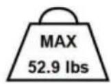

BESOIN D'AIDE? CONTACTEZ-NOUS!
www.vevor.com/support
3
Connect With monitor
Use a wrench (G) to screw the screws (A/B) into the four holes at the back of the monitor to avoid damaging the moni-tor by over tightening the screws.

4

When the display is inserted into the quick release head, make sure the knob is vertical.

After insertion, rotate the knob 90 degrees to the left.

natural_image
Technical line drawing of a mechanical assembly with a bracket and panel (no text or symbols)

natural_image
Technical line drawing of a mechanical arm assembly mounted on a flat panel (no text or symbols)5-1
Case 1: Monitor/Arm fall down (after install your monitor)
Press the arm to make it keep it in horizontal position and then use the Allen Key to adjust the screw on the arm. Turn counter-clockwise("+ " direction) to increase gas spring tension till can hold the weight of your monitor.
Note: You may need to turn the screw by many circles to tighten the arm.

5-2
Case 2: Monitor/Arm pops up (after install your monitor)
Press the arm to make it keep it in horizontal position and then use the Allen Key to adjust the screw on the arm. Turn clockwise("- " direction) to reduce gas spring tension till can stay the position needed.
Note: You may need to turn the screw by many circles to tighten the arm.
6
Adjust Flexibility

If you feel the pitching angle too tight or too loose when adjusting the mount, please adjust the Screw
7
Cable Management

natural_image
Technical line drawing of two mechanical linkage components (no text or symbols)8
Adjustable Instruction
Fabricant : Shanghaimuxinmuyeyouxiangongsi Adresse :
Shuangchenglu 803nong11hao1602A-1609shi, baoshanqu, shanghai 200000 CN.
Importé en AUS : SIHAO PTY LTD. 1 ROKEVA STREETEASTWOOD NSW 2122 Australie Importé aux USA :
Sanven Technology Ltd. Suite 250, 9166 Anaheim Place, Rancho Cucamonga, CA 91730
E-CrossStu GmbH
Mainzer Landstr.69, 60329
A/S YH Consulting Limited Bureau 147, Centurion
Maison, London Road, Staines-upon-Thames, Surrey, TW18 4AX
VEVOR®
TOUGH TOOLS, HALF PRICE
natural_image
Technical line drawing of two articulated robotic arms with mounting flanges and a separate base mount (no text or symbols)


www.vevor.com/support
3
Connect With monitor
Use a wrench (G) to screw the screws (A/B) into the four holes at the back of the monitor to avoid damaging the moni-tor by over tightening the screws.
4

When the display is inserted into the quick release head, make sure the knob is vertical.
After insertion, rotate the knob 90 degrees to the left.

natural_image
Technical line drawing of a mechanical assembly with a bracket and panel (no text or symbols)

natural_image
Technical line drawing of a mechanical arm assembly mounted on a flat panel (no text or symbols)5-1
Case 1: Monitor/Arm fall down (after install your monitor)
Press the arm to make it keep it in horizontal position and then use the Allen Key to adjust the screw on the arm. Turn counter-clockwise("+ " direction) to increase gas spring tension till can hold the weight of your monitor.
Note: You may need to turn the screw by many circles to tighten the arm.
Case 2: Monitor/Arm pops up (after install your monitor)
Press the arm to make it keep it in horizontal position and then use the Allen Key to adjust the screw on the arm. Turn clockwise("- " direction) to reduce gas spring tension till can stay the position needed.
Note: You may need to turn the screw by many circles to tighten the arm.
6
Adjust Flexibility

If you feel the pitching angle too tight or too loose when adjusting the mount, please adjust the Screw
7
Cable Management

natural_image
Technical line drawing of two mechanical linkage components (no text or symbols)8
Adjustable Instruction

Hersteller: Shanghaimuxinmuyeyouxiangongsi Adresse:
Shuangchenglu 803nong11hao1602A-1609shi, baoshanqu, Shanghai 200000 CN.
C/O YH Consulting Limited Office 147, Centurion
Haus, London Road, Staines-upon-Thames, Surrey, TW18 4AX
VEVOR®
TOUGH TOOLS, HALF PRICE
natural_image
Technical line drawing of two articulated robotic arms with mounting flanges and a separate base mount (no text or symbols)

www.vevor.com/support
natural_image
Technical line drawing of a mechanical bracket assembly (no text or symbols)1a-2b
1a-3

natural_image
Mechanical assembly diagram showing a clamping mechanism with a rotating arm and labeled component G (no text or symbols beyond label)Metodo 2----1b
3
Connect With monitor
Use a wrench (G) to screw the screws (A/B) into the four holes at the back of the monitor to avoid damaging the moni-tor by over tightening the screws.

4
When the display is inserted into the quick release head, make sure the knob is vertical.

After insertion, rotate the knob 90 degrees to the left.

natural_image
Technical line drawing of a mechanical assembly with a bracket and panel (no text or symbols)

natural_image
Technical line drawing of a mechanical arm assembly mounted on a flat panel (no text or symbols)5-1
Case 1: Monitor/Arm fall down (after install your monitor)
Press the arm to make it keep it in horizontal position and then use the Allen Key to adjust the screw on the arm. Turn counter-clockwise("+ " direction) to increase gas spring tension till can hold the weight of your monitor.
Note: You may need to turn the screw by many circles to tighten the arm.
5-2
Case 2: Monitor/Arm pops up (after install your monitor)
Press the arm to make it keep it in horizontal position and then use the Allen Key to adjust the screw on the arm. Turn clockwise("- " direction) to reduce gas spring tension till can stay the position needed.
Note: You may need to turn the screw by many circles to tighten the arm.

6
Adjust Flexibility

If you feel the pitching angle too tight or too loose when adjusting the mount, please adjust the Screw
7
Cable Management

natural_image
Technical line drawing of two mechanical linkage components (no text or symbols)8
Adjustable Instruction

Importato in AUS: SIHAO PTY LTD. 1 ROKEVA STREETEASTWOOD NSW 2122 Australia Importato negli
USA: Sanven Technology Ltd. Suite 250, 9166 Anaheim Place, Rancho Cucamonga, CA 91730
C/O YH Consulting Limited Ufficio 147, Centurion
Casa, London Road, Staines-upon-Thames, Surrey, TW184AX
VEVOR®
TOUGH TOOLS, HALF PRICE
natural_image
Technical line drawing of two articulated robotic arms with mounting flanges and a separate base mount (no text or symbols)


3
Connect With monitor
Use a wrench (G) to screw the screws (A/B) into the four holes at the back of the monitor to avoid damaging the moni-tor by over tightening the screws.

4

When the display is inserted into the quick release head, make sure the knob is vertical.

After insertion, rotate the knob 90 degrees to the left.
natural_image
Technical line drawing of a mechanical assembly with a bracket and panel (no text or symbols)

natural_image
Technical line drawing of a mechanical arm assembly mounted on a flat panel (no text or symbols)5-1
Case 1: Monitor/Arm fall down (after install your monitor)
Press the arm to make it keep it in horizontal position and then use the Allen Key to adjust the screw on the arm. Turn counter-clockwise("+ " direction) to increase gas spring tension till can hold the weight of your monitor.
Note: You may need to turn the screw by many circles to tighten the arm.

5-2
Case 2: Monitor/Arm pops up (after install your monitor)
Press the arm to make it keep it in horizontal position and then use the Allen Key to adjust the screw on the arm. Turn clockwise("- " direction) to reduce gas spring tension till can stay the position needed.
Note: You may need to turn the screw by many circles to tighten the arm.
6
Adjust Flexibility

If you feel the pitching angle too tight or too loose when adjusting the mount, please adjust the Screw
7
Cable Management

natural_image
Technical line drawing of two mechanical linkage components (no text or symbols)8
Adjustable Instruction

Casa, London Road, Staines-upon-Thames, Surrey, TW18 4AX
VEVOR®
TOUGH TOOLS, HALF PRICE
natural_image
Technical line drawing of two articulated robotic arms with mounting flanges and a separate base mount (no text or symbols)


POTRZEBUJESZ POMOCY? SKONTAKTUJ SIĘ Z NAMI!
www.vevor.com/support
3
Connect With monitor
Use a wrench (G) to screw the screws (A/B) into the four holes at the back of the monitor to avoid damaging the moni-tor by over tightening the screws.
4

When the display is inserted into the quick release head, make sure the knob is vertical.

After insertion, rotate the knob 90 degrees to the left.

natural_image
Technical line drawing of a mechanical assembly with a bracket and panel (no text or symbols)

natural_image
Technical line drawing of a mechanical arm assembly mounted on a flat panel (no text or symbols)5-1
Case 1: Monitor/Arm fall down (after install your monitor)
Press the arm to make it keep it in horizontal position and then use the Allen Key to adjust the screw on the arm. Turn counter-clockwise("+ " direction) to increase gas spring tension till can hold the weight of your monitor.
Note: You may need to turn the screw by many circles to tighten the arm.
5-2
Case 2: Monitor/Arm pops up (after install your monitor)
Press the arm to make it keep it in horizontal position and then use the Allen Key to adjust the screw on the arm. Turn clockwise( ^™ - ^™ direction) to reduce gas spring tension till can stay the position needed.
Note: You may need to turn the screw by many circles to tighten the arm.
6
Adjust Flexibility

If you feel the pitching angle too tight or too loose when adjusting the mount, please adjust the Screw
7
Cable Management
natural_image
Technical line drawing of two mechanical linkage components (no text or symbols)8
Adjustable Instruction

Producent: Shanghaimuxinmuyeyouxiangongsi Adres:
Shuangchenglu 803nong11hao1602A-1609shi, baoshanqu, szanghaj 200000 CN.
Importowane do AUS: SIHAO PTY LTD. 1 ROKEVA STREETEASTWOOD NSW 2122 Australia Importowane do
USA: Sanven Technology Ltd. Suite 250, 9166 Anaheim Place, Rancho Cucamonga, CA 91730
| Przedstawiciel UE |
E-CrossStu GmbH
Mainzer Landstr.69, 60329
Frankfurt nad Menem.
| REP WIELKIEJ BRYTANII |
YH CONSULTING LIMITED.
C/O YH Consulting Limited Biuro 147, Centurion
Dom, London Road, Staines-upon-Thames, Surrey, TW18 4AX
VEVOR®
TOUGH TOOLS, HALF PRICE
natural_image
Technical line drawing of two articulated robotic arms with mounting flanges and a separate base mount (no text or symbols)


HULP NODIG? NEEM CONTACT MET ONS OP!
www.vevor.com/support
3
Connect With monitor
Use a wrench (G) to screw the screws (A/B) into the four holes at the back of the monitor to avoid damaging the moni-tor by over tightening the screws.

4

When the display is inserted into the quick release head, make sure the knob is vertical.

After insertion, rotate the knob 90 degrees to the left.
natural_image
Technical line drawing of a mechanical assembly with a bracket and panel (no text or symbols)
natural_image
Technical line drawing of a mechanical arm assembly mounted on a flat panel (no text or symbols)5-1
Case 1: Monitor/Arm fall down (after install your monitor)
Press the arm to make it keep it in horizontal position and then use the Allen Key to adjust the screw on the arm. Turn counter-clockwise("+ " direction) to increase gas spring tension till can hold the weight of your monitor.
Note: You may need to turn the screw by many circles to tighten the arm.

5-2
Case 2: Monitor/Arm pops up (after install your monitor)
Press the arm to make it keep it in horizontal position and then use the Allen Key to adjust the screw on the arm. Turn clockwise( ^™ - ^™ direction) to reduce gas spring tension till can stay the position needed.
Note: You may need to turn the screw by many circles to tighten the arm.
6
Adjust Flexibility
If you feel the pitching angle too tight or too loose when adjusting the mount, please adjust the Screw
7
Cable Management

natural_image
Technical line drawing of two mechanical linkage components (no text or symbols)8
Adjustable Instruction

Fabrikant: Shanghaimuxinmuyeyouxiangongsi Adres:
Shuangchenglu 803nong11hao1602A-1609shi, baoshanqu, shanghai 200000 CN.
C/O YH Consulting Limited Kantoor 147, Centurion
Huis, London Road, Staines-upon-Thames, Surrey, TW18 4AX
VEVOR®
TOUGH TOOLS, HALF PRICE
Technische ondersteuning en e-garantiecertificaat www.vevor.com/support
VEVOR®
TOUGH TOOLS, HALF PRICE
natural_image
Technical line drawing of two articulated robotic arms with mounting flanges and a separate base mount (no text or symbols)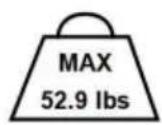


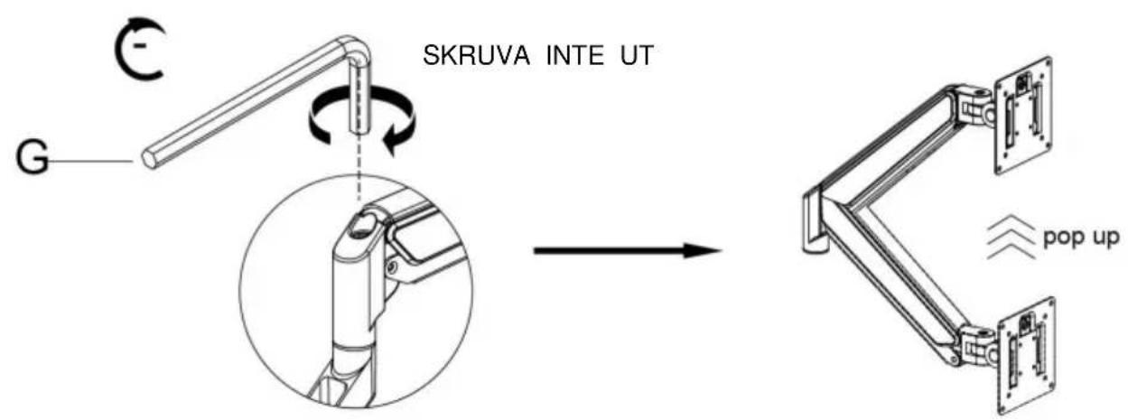
BEHÖVER HJÄLP? KONTAKTA OSS!
1a-3
natural_image
Technical line drawing of a mechanical clamp or clamping device with labeled component G and rotational arrow (no text or symbols beyond label)Metod 2----1b
3
Connect With monitor
Use a wrench (G) to screw the screws (A/B) into the four holes at the back of the monitor to avoid damaging the moni-tor by over tightening the screws.

4

When the display is inserted into the quick release head, make sure the knob is vertical.

After insertion, rotate the knob 90 degrees to the left.

natural_image
Technical line drawing of a mechanical assembly with a bracket and panel (no text or symbols)

natural_image
Technical line drawing of a mechanical arm assembly mounted on a flat panel (no text or symbols)5-1
Case 1: Monitor/Arm fall down (after install your monitor)
Press the arm to make it keep it in horizontal position and then use the Allen Key to adjust the screw on the arm. Turn counter-clockwise("+ " direction) to increase gas spring tension till can hold the weight of your monitor.
Note: You may need to turn the screw by many circles to tighten the arm.
5-2
Case 2: Monitor/Arm pops up (after install your monitor)
Press the arm to make it keep it in horizontal position and then use the Allen Key to adjust the screw on the arm. Turn clockwise( ^™ - ^™ direction) to reduce gas spring tension till can stay the position needed.
Note: You may need to turn the screw by many circles to tighten the arm.
6
Adjust Flexibility

If you feel the pitching angle too tight or too loose when adjusting the mount, please adjust the Screw
7
Cable Management

natural_image
Technical line drawing of two mechanical linkage components (no text or symbols)8
Adjustable Instruction

Tillverkare: Shanghaimuxinmuyeyouxiangongsi Adress:
Shuangchenglu 803nong11hao1602A-1609shi, baoshanqu, shanghai 200000 CN.
Importerad till AUS: SIHAO PTY LTD. 1 ROKEVA STREETEASTWOOD NSW 2122 Australien Importerad till
USA: Sanven Technology Ltd. Suite 250, 9166 Anaheim Place, Rancho Cucamonga, CA 91730
| EC | REP |
E-CrossStu GmbH
Mainzer Landstr.69, 60329
Frankfurt am Main.
| UK | REP |
YH CONSULTING LIMITED.
C/O YH Consulting Limited Office 147, Centurion
House, London Road, Staines-upon-Thames, Surrey, TW18 4AX
VEVOR®
TOUGH TOOLS, HALF PRICE


