OSM-1 - Sander Vevor - Free user manual and instructions
Find the device manual for free OSM-1 Vevor in PDF.

| Brand | Vevor |
| Model | OSM-1 |
| Type | Spindle Sander |
| Power Supply | 120 V / 220-240 V, 60 Hz / 50 Hz, 450 W |
| No-Load Speed | 2000 RPM |
| Oscillations | 58 OPM |
| Spindle Size | 1/2" |
| Sanding Sleeve Sizes | 1/2", 3/4", 1", 1-1/2", 2", 3" (grit 80) |
| Maximum Workpiece Height | 3-6/7" |
| Weight | 19.8 lbs (approx. 9 kg) |
| Compatible Materials | Wood and similar materials |
| Polarized Plug | Yes (one wider prong) |
| Electrical Protection | GFCI recommended |
| Recommended Extension Cord | 18 to 14 gauge depending on length (up to 150 ft) |
| Safety Key Switch | Yes |
| Dust Collection System | 1.5" port (adapter not included) |
| Mounting | On workbench or plate with clamps (hardware not provided) |
| Required Protective Equipment | Safety glasses, hearing protection, dust mask |
| Maintenance | Clean with soft cloth, vacuum; no solvents |
| Lubrication | Sealed bearings, no lubrication needed |
| Warranty | Conditioned on use of dust collection system |
| Manufacturer | Shanghaimuxinmuyeyouxiangongsi, Shanghai, China |
| Importer (USA) | Sanven Technology Ltd., Anaheim, CA |
| Importer (Australia) | SIHAO PTY LTD., NSW |
Frequently Asked Questions - OSM-1 Vevor
User questions about OSM-1 Vevor
0 question about this device. Answer the ones you know or ask your own.
Ask a new question about this device
Download the instructions for your Sander in PDF format for free! Find your manual OSM-1 - Vevor and take your electronic device back in hand. On this page are published all the documents necessary for the use of your device. OSM-1 by Vevor.
USER MANUAL OSM-1 Vevor
Affordable. Reliable. Home Improvement.
SPINDLE SANDER
MODEL: OSM-1
MODEL: OSM-1

natural_image
Technical line drawing of a mechanical device with no visible text or symbolsThis is the original instruction, please read all manual instructions care before operating. VEVOR reserves a clear interpretation of our user manual. The appearance of the product shall be subject to the product received. Please forgive us that we won't inform you again if there are technology or software updates on our product.
 | Warning-To reduce the risk of injury, user must read instruction manual carefully. |
 | This symbol, placed before a safety comment, indicates a precaution, warning, or danger. Ignoring this warning may be an accident. To reduce the risk of injury, fire, or electrocussion please always follow the recommendation shown below. |
 | CORRECT DISPOSALThis product is subject to the provision of european Directi 2012/19/EU. The symbol showing a wheelie bin crossed through indicates that the product requires separate refuse collection in European Union. This applies to the product and all access marked with this symbol. Products marked as such may not be discarded with normal domestic waste, but must be taken on a collection point for recycling electrical and electronic device. |
 | Warning- Be sure to wear eye protectors when using this |
 | Warning- Be sure to wear ear protectors when using this |
 | Warning- Be sure to wear dust masks when using this procedure. |
 | Warning- Disconnect mains plug from electrical outlet |
SPECIFICATIONS
| Power | AC120V, 60 Hz, 450W | AC220—240V, 50Hz, 450W |
| No Load Speed | 2000RPM/-5% | |
| Oscillations | 58 OPM | |
| Spindle Size | 1/2" | |
| Sanding Sleeve Sizes | 1/2", 3/4", 1", 1-1/2", 2", 3" (80 Grit) | |
| Maximum Workpiece Height | 3-6/7" | |
| Weight | 19.8 Pounds | |
SAFETY GUIDELINES

WARNING!
Read all safety warnings and all instructions. Failure to follow the warning and instructions may result in electric shock, fire and/or serious injury.
SAFETY GUIDELINES - DEFINITIONS
WORK AREA SAFETY
- Keep work area clean and well lit. Cluttered or dark areas invite accide
-
Do not operate power tools in explosive atmospheres, such as in the presence of flammable liquids, gases or dust. Power tools create sparks w may ignite the dust or fumes.
-
Keep children and bystanders away while operating a power tool.
Distractions can cause you to lose control.
ELECTRICAL SAFETY
-
Power tool plugs must match the outlet. Never modify the plug in ar Do not use any adapter plugs with earthed (grounded) power tools. Unm fied plugs and matching outlets will reduce risk of electric shock.
-
Avoid body contact with earthed or grounded surfaces such as pipes, radiators, ranges and refrigerators. There is an increased risk of electric sh if your body is earthed or grounded.
-
Do not expose power tools to rain or wet conditions. Water entering a power tool will increase the risk of electric shock.
- Do not abuse the cord. Never use the cord for carrying, pulling or tging the power tool. Keep cord away from heat, oil, sharp edges or mo parts. Damaged or entangled cords increase the risk of electric shock.
- When operating a power tool outdoors, use an extension cord suitable outdoor use. Use of a cord suitable for outdoor use reduces the risk of ele shock.
- If operating a power tool in a damp location is unavoidable, use a g fault circuit interrupter (GFCI) protected supply. Use of a GFCI reduces the risk of electric shock.
PERSONAL SAFETY
- Stay alert, watch what you are doing and use common sense when operating a power tool. Do not use a power tool while you are tired or the influence of drugs, alcohol or medication. A moment of inattention whi operating power tools may result in serious personal injury.
- Use personal protective equipment. Always wear eye protection. Protect equipment such as a respiratory mask, non-skid safety shoes and hearing protection used for appropriate conditions will reduce the risk of personal injury
- Prevent unintentional starting. Ensure the switch is in the off-position before connecting to power source and/or battery pack, picking up or carrying the tool. Carrying power tools with your finger on the switch or energizing power tools that have the switch on invites accidents.
- Remove any adjusting key or wrench before turning the power tool of wrench or a key left attached to a rotating part of the power tool may resu personal injury.
- Do not overreach. Keep proper footing and balance at all times. This enables better control of the power tool in unexpected situations.
-
Dress properly. Do not wear loose clothing or jewelry. Keep your hair clothing away from moving parts. Loose clothes, jewelry or long hair can be caught in moving parts.
-
If devices are provided for the connection of dust extraction and collected facilities, ensure these are connected and properly used. Use of dust collection can reduce dust-related hazards.
POWER TOOL USE AND CARE
- Do not force the power tool. Use the correct power tool for your application. The correct power tool will do the job better and safer at the r which it was designed.
- Do not use the power tool if the switch does not turn it on and of power tool that cannot be controlled with the switch is dangerous and must repaired.
- Disconnect the plug from the power source and/or the battery pack for the power tool before making any adjustments, changing accessories, or storing power tools. Such preventive safety measures reduce the risk of state the power tool accidentally.
- Store idle power tools out of the reach of children and do not allow persons unfamiliar with the power tool or these instructions to operate the power tool. Power tools are dangerous in the hands of untrained users.
- Maintain power tools. Check for misalignment or binding of moving power breakage of parts and any other condition that may affect the power tool operation. If damaged, have the power tool repaired before use. Many accidents are caused by poorly maintained power tools.
- Keep cutting tools sharp and clean. Properly maintained cutting tools with sharp cutting edges are less likely to bind and are easier to control.
- Use the power tool, accessories and tool bits, etc. in accordance with these instructions, taking into account the working conditions and the work to be performed. Use of the power tool for operations different from those intended could result in a hazardous situation.
- Use clamps to secure your workpiece to a stable surface. Holding a workpiece by hand or using your body to support it may lead to loss of co
- KEEP GUARDS IN PLACE and in working order.
SERVICE
- Have your power tool serviced by a qualified repair person using only
identical replacement parts. This will ensure that the safety of the power to maintained.
CALIFORNIA PROPOSITION 65 WARNING
Some dust created by power sanding, sawing, grinding, drilling, and other construction activities may contain chemicals, including lead, known to the State California to cause cancer, birth defects, or other reproductive harm. Wash has after handling. Some examples of these chemicals are:
- Lead from lead-based paints.
- Crystalline silica from bricks, cement, and other masonry products.
- Arsenic and chromium from chemically treated lumber.
Your risk from these exposures varies depending on how often you do this work. To reduce your exposure to these chemicals, work in a well-ventilated with approved safety equipment such as dust masks specially designed to filter microscopic particles.
SPINDLE SANDER SAFETY
WARNING!
Do not operate the power tool until you have read and understood the following instructions and the warning labels.
-
TOOL PURPOSE. This sander is designed to sand wood or wood-like pro only. Sanding or grinding other materials could result in fire, injury, or damage the workpiece. Using the machine for any other purpose for which it is not designed may result in serious injuries, machine damage and voiding of the warranty.
-
MACHINE MOUNTING. For operation safety, the sander must be securely mounted onto a flat and stable surface or stand.
3. PERSONAL SAFETY
- Always wear ANSI Z87.1-approved glasses with side shields, hearing protect and a dust mask.
- Do not wear loose clothing or jewelry, as they might get drawn in by the back long hair.
-
DO NOT wear gloves while operating this machine.
-
ELECTRIC CORDS. Keep cords away from heat, oil, sharp edges, and m parts of the tool. Have an electrician replace or repair damaged or worn cor immediately.
-
TOOL & ACCESSORIES INSPECTION. Before operation, check the tool ar accessories for any damage or missing parts. Do not use the tool if any pa missing or damaged. Make sure all adjustments are correct and all connection are tight. Keep all guards in place.
6. SANDING ACCESSORIES
- Do not use sanding sleeves or drums that are damaged, torn, or loose. R worn or damaged sanding sleeves before operation.
- Always unplug the unit before making adjustments or changing sandpaper, rubber drums or throat plates.
• Always use the throat plate that matches the diameter of the drum to min the gap between the drum and the throat plate opening; this will reduce the personal injury.
7. WORKPIECE REQUIREMENTS
- Only stand workpieces sturdy enough to withstand the force of the sanding spindle.
- Inspect the workpiece for imperfections, nails, staples, etc. before sanding. Never sand stock that has questionable imperfections or embedded foreign objects.
- When sanding a large workpiece, provide additional support. Do not sand with the workpiece unsupported.
-
Sand only one workpiece at a time.
-
PREVENTING ACCIDENTAL STARTING. Make sure the power switch is in OFF position prior to plugging in the machine. Always make sure the power is in the OFF position and the machine is unplugged when doing any clean assembly, setup operations, or when not in use.
-
Do not operate this tool until it is completely assembled and installed acc to the instructions.
-
Remove scrap pieces and other objects from the table and sanding sleeve before turning ON the sander.
11. FEEDING THE WORKPIECE
- Allow spindle to reach full speed before feeding the workpiece. Do not turn
machine while the sanding sleeve is contacting the workpiece.
- Be aware of the direction of the spindle's rotation (counterclockwise). Only the workpiece against the rotation of the spindle.
-
Firmly hold the workpiece and lightly ease it against the spindle. Do not form jam a workpiece into the sanding surface.
-
Do not touch moving pieces. Keep hands away from the drum during operation.
If cleaning is necessary, use a brush to remove sawdust and chips instead of hands.
-
Never perform layout, assembly or set-up work on the table while the sa operating.
-
After turning off the sander, wait until the spindle comes to a complete before touching the workpiece.
-
Always turn off and unplug the machine before cleaning, making adjustment or changing attachments. Accidental start-ups may occur if the tool is plugged during an accessory change or adjustment.
-
CLEANING. Never use solvents to clean plastic parts. Solvents could dissolve or otherwise damage the material. Use only a soft damp cloth to clean plastic parts.
-
REPLACEMENTS. Should any component of your sander be missing/damaged or fail in any way, shut off the switch and remove the plug from power outlet. Replace the missing, damaged, or failed parts using only identical replacement parts before resuming operation.
These safety instructions can't possibly warn of every scenario that may arise with this tool, so always make sure to stay alert and use common sense during operation.
ELECTRICAL SAFETY
-
POLARIZED PLUGS. To reduce the risk of electric shock, this equipment polarized plug (one blade is wider than the other). This plug will fit in a po outlet only one way. If the plug does not fit fully in the outlet, reverse the still does not fit, contact a qualified electrician to install a proper outlet. Do modify the machine plug or the extension cord in any way.
-
GROUND FAULT CIRCUIT INTERRUPTER PROTECTION (GFCI) should be
provided on the circuit or outlet used for this power tool to reduce the risk electric shock.
- SERVICE AND REPAIR. To avoid danger, electrical appliances must only be repaired by qualified service technician using original replacement parts.
GUIDELINES AND RECOMMENDATIONS FOR EXTENSION CORDS
When using an extension cord, be sure to use one heavy enough to carry current your product will draw. An undersized cord will cause a drop in line resulting in loss of power and overheating. The table below shows the correct to be used according to cord length and ampere rating. When in doubt, use heavier cord. The smaller the gauge number, the heavier the cord.
| AMPERAGE | REQUIRED GAUGE FOR EXTENSION CORDS | |||
| 25 ft. | 50 ft. | 100 ft. | 150 ft. | |
| 4A | 18 gauge | 16 gauge | 16 gauge | 14 gauge |
- EXAMINE EXTENSION CORD BEFORE USE. Make sure your extension cc is properly wired and in good condition. Always replace a damaged extension or have it repaired by a qualified person before using it.
- DO NOT ABUSE EXTENSION CORD. Do not pull on cord to disconnect receptacle; always disconnect by pulling on plug. Disconnect the extension cord from the receptacle before disconnecting the product from the extension cord. Protect your extension cords from sharp objects, excessive heat and damp/we areas.
- USE A SEPARATE ELECTRICAL CIRCUIT FOR YOUR TOOL. This circuit must not be less than a 12-gauge wire and should be protected with a 15A time-delayed fuse.
Before connecting the motor to the power line, make sure the switch is in t position and the electric current is rated the same as the current stamped o motor nameplate. Running at a lower voltage will damage the motor.
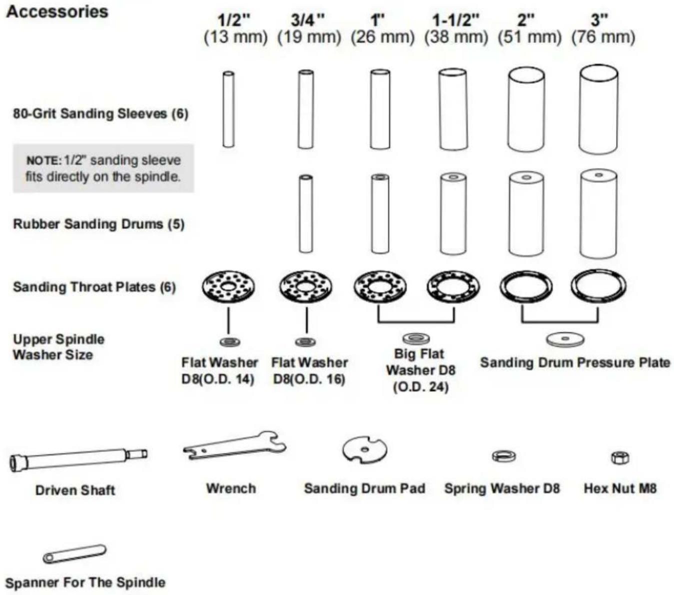
PACKAGE CONTENTS
Before using the spindle sander, you must configure the machine by installing appropriate sanding drum, sanding sleeve, throat plate and spindle washer for
your operation. Check your packing list against the diagram below. If any pa1 damaged or missing, please contact our customer service.
PACKING LIST
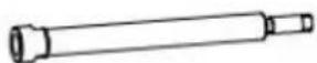
bar
| Tool Type | Size (mm) | Description | |-----------|-----------|-------------| | 1/2" | 13 | 1/2" (13 mm) | | 3/4" | 19 | 3/4" (19 mm) | | 1" | 26 | 1" (26 mm) | | 1-1/2" | 38 | 1-1/2" (38 mm) | | 2" | 51 | 2" (51 mm) | | 3" | 76 | 3" (76 mm) | | Upper Spindle Washer Size | - | Flat Washer D8(O.D. 14) | | Upper Spindle Washer Size | - | Flat Washer D8(O.D. 16) | | Upper Spindle Washer Size | - | Big Flat Washer D8 (O.D. 24) | | Sanding Throat Plates | - | Sanding Throat Plates (6) | | Sanding Drum Pressure Plate | - | Sanding Drum Pressure Plate | | Driven Shaft | - | Wrench | | Wrench | - | Sanding Drum Pad | | Spring Washer D8 | - | Spring Washer D8 | | Hex Nut M8 | - | Hex Nut M8 | | Spanner For The Spindle | - | - |OPERATING INSTRUCTIONS

WARNING!
Do not plug in or turn on the tool until it is fully assembled according to the instructions.
Failure to follow the safety instructions may result in serious personal injury.
Refer to the packing list diagram on page 8 to ensure that you are using t sizes of throat plates, drums and washers for each respective sanding sleeve ensure the workpiece can be properly supported and to minimize clearance, t the throat plate that matches the drum and sleeve that you'll be working with size of the throat plate is marked on the plate's surface.
NOTE: The smallest size sanding sleeve does not include a drum. It goes c onto the bare spindle.
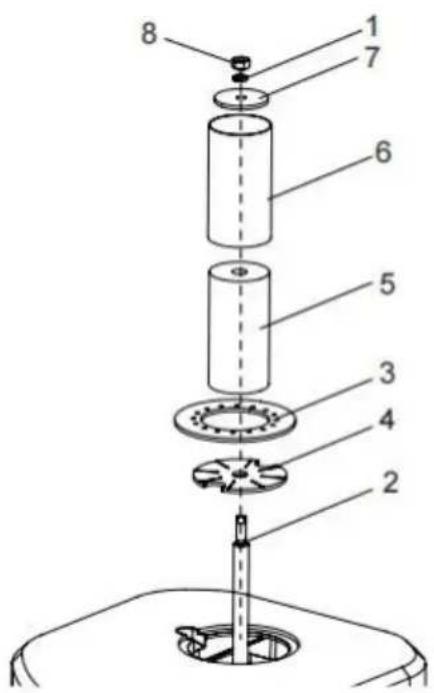
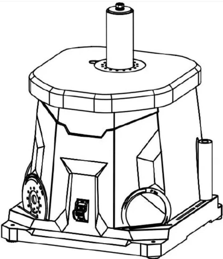
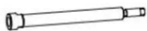
INSTALLATION OF SPINDLE
- Disconnect the machine from the power source
- Insert Main Shaft I (2) into Main Shaft II (1)
- Hold the Main Shaft II (1) in position using the wrench(3).
- Screw the Main Shaft I (2) clockwise onto the Shaft II (1) using the spanner for the spindle (4).
INSTALLING THE ACCESSORIES NG!
- Slide the lower spindle washer (4) over the spindle shaft (2).
- Install the preferred rubber drum (5) onto spindle shaft (2), followed by the correspond sanding sleeve (6) and throat plate (3). Make the printed side of the throat plate is facing
NOTE: The 1/2" sleeve is installed directly or spindle.
- Secure the sanding attachment in place with appropriate size sanding drum pressure plate and flat washer D8 (1).
Tighten the top hex nut M8 (8) with a wrench the sanding drum is fully expanded and firmly
the sanding sleeve. The sleeve cannot rotate freely without the sanding drum rotating.
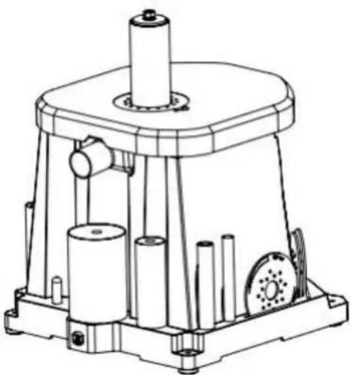
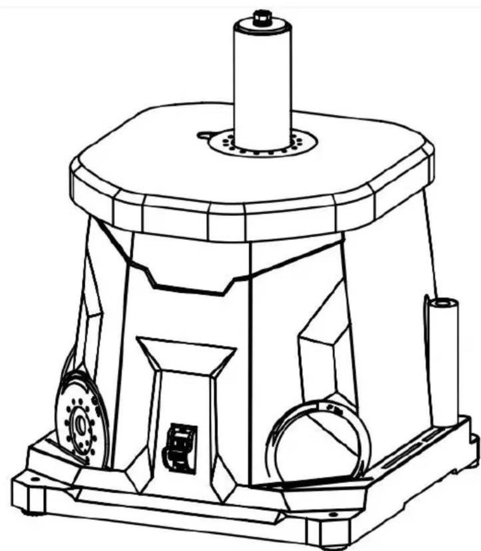
MACHINE MOUNTING
For safe operation, the machine must be secured onto a flat, secure worker stand.
The base of the machine has four 6 mm mounting holes. Place the sander mounting surface, and insert a pencil through the mounting holes to mark the locations. Remove the sander and drill out the mounting holes. Then align the sander base over the mounting holes and secure the machine using four mo bolts, washers, locking washers and hex nuts (mounting hardware not included). Securely tighten the hex nuts.
For temporary mounting, secure the sander to a mobile mounting board and large C-Clamps to secure the mounting board to a solid surface.
UPPER GUARD

Sanding operations are dusty and can produce particles that are harmful to y health. Always wear a dust mask and use an adequate dust collection syster
To connect a dust collection system to the machine:
- Fit a 1.5-inch dust hose (not included) of dust port and secure the hose in place with clamp if needed (not included).
- Tug the hose to make sure the fitting is tight fit is necessary for proper performance
- Connect the other end of the dust hose, dust collection system of your choice. A dual adapter may be needed (not included), dependence on the inlet size of your dust extractor. The port has an outer diameter
of 1.5 inches, and an inner diameter of 1.4 inches.
NOTE: Failure to use a dust collection system will void the warranty on this You must use a dust collection system for the warranty to be valid.
natural_image
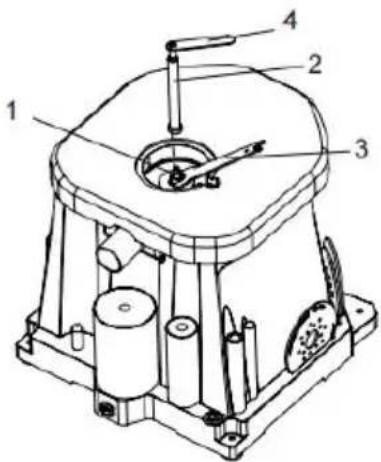
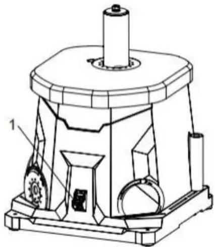
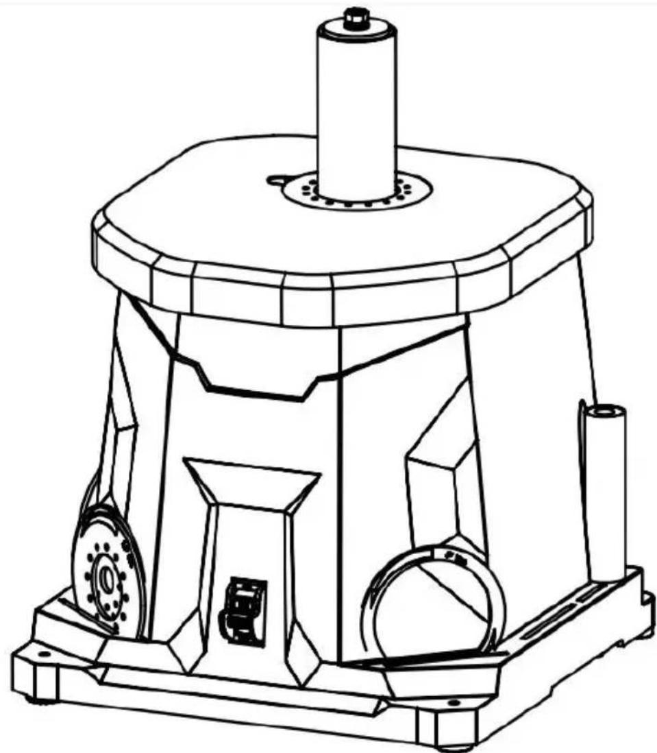
Technical line drawing of a mechanical device with cylindrical components and mounting base (no text or symbols)ON/OFF SWITCH WITH SAFETY KEY
The keyed ON/OFF switch (1) is intended to prevent unauthorized use of the sander.
- To turn the sander ON, insert the safety the key slot in the center of the switch. Lift switch up to turn ON the sander.
- To turn the sander OFF, push switch dow Remove the safety key when the sander has to a complete stop by gently pulling it out.
WARNING: Remove the safety key whenever the s
is not in use. Place the key in a safe place and out of the reach of children
natural_image
Technical line drawing of a mechanical device with labeled components (no text or symbols present)- Make sure that the machine has been securely mounted, and all accessor
have been properly installed according to the instructions on page 9-10 section. - Plug in and turn ON the sander. Let the reach full speed.
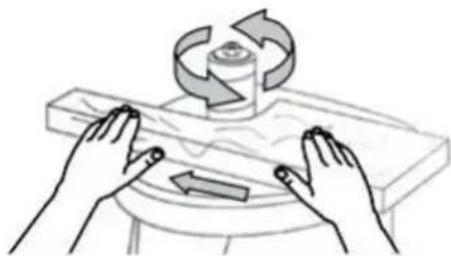
- Maintain a firm grip with both hands on workpiece for maximum control. Slowly guide workpiece against the rotation of the spindle.
NOTE: The spindle rotates in a counterclockwise direction. Guide the workpiece from the right to left. If you guide the workpiece in the opposite direction, the of the spinning sanding sleeve will tend to throw or bounce the workpiece at from the sanding sleeve, possibly resulting in injuries.
- Maintain downward pressure on the workpiece against the table, gently wo it along the sanding sleeve until the desired curve has been created. Do not the workpiece against the sanding sleeve.
- When you are finished, turn OFF the sander and wait for the spindle to a complete stop.
- Remove the safety key and unplug the machine from the outlet. Follow the maintenance instructions on the next page to clean and maintain your sander
natural_image
Illustration of hands operating a rotating mechanical device with a rotating knob (no text or symbols)MAINTENANCE

WARNING!
To avoid accidents, turn OFF and unplug the tool from the electrical outlet by cleaning, adjusting, or performing any maintenance or lubrication work.

WARNING!
Any attempt to repair or replace electrical parts on this tool may be hazardo Servicing of the tool must be performed by a qualified technician. When serv use only identical replacement parts. Use of other parts may be hazardous o induce product failure.
ROUTINE INSPECTION
Before each use, inspect the general condition of the tool. If any of these for conditions exist, do not use until parts are replaced or the sharpener is prop repaired.
Check for:
- Loose hardware or improper mounting,
- Misalignment or binding of moving parts,
• Damaged cord/electrical wiring, - Cracked or broken parts, and
- Any other condition that may affect its safe operation
CLEANING & STORAGE
- After every operation, use a vacuum to remove dust and chips from the surfaces, motor housing and work area. Keep the ventilation openings free from dust and debris to prevent the motor from overheating.
- Wipe the tool surfaces clean with a soft cloth or brush. Make sure water not get into the tool.
- Periodically, remove the throat plate and lower spindle washer and remove dust accumulation in the throat plate area.
CAUTION: Most plastics are susceptible to damage from various types of commercial solvents. Do not use any solvents or cleaning products that could damage the plastic parts.
Some of these include but are not limited to: gasoline, carbon tetrachloride, chlorinated cleaning solvents, and household detergents that contain ammonia. 4. Store the tool in a clean and dry place away from the reach of children. sanding accessories away from extremely hot/dry temperatures. Do not bend or fold the sanding sleeves.
LUBRICATION
All ball bearings are sealed and permanently lubricated. No further lubrication required.
PRODUCT DISPOSAL
Used power tools should not be disposed of together with household waste. product contains electronic components that should be recycled. Please take tl product to your local recycling facility for responsible disposal and to minimize environmental impact.
TROUBLESHOOTING GUIDE
WARNING!
To avoid injury from an accidental start, turn the switch OFF and always remove the plug from the power source before making any adjustments.
| PROBLEM | PROBLEM CAUSE | SUGGESTED CORRECTIVE ACTION |
| Sander does not turn on. | 1. Power cord or extension cord damaged or not proper plugged in.2. Safety key is removed from power switch.3. Defective power switch, defective motor or wiring, sh circuit or loose connections.4. Circuit breaker is tripped.5. Worn carbon brushes. | 1. Check the power cord, extension cord, power plug and the power outlet. Make sure the tool is proposed plugged in. Do not use the if an is damaged.2. Insert the safety key into the power switch.3. Stop using the tool and contact customer service. Repairs must be done by a qualified technician.4. Push circuit breaker to reset.5. Replace carbon brushes. |
| Motor overheats. | 1. Motor overloaded.2. Extension cord too long, an insufficient gauge.3. Dust collection not being used. | 1. Reduce load on motor - reduce pressure on the workpiece being sanded.2. Utilize an extension cord of appropriate gauge and length or tool directly into outlet.3. Use dust collection. |
| Sanding grains easily rub off. | 1. Sanding sleeve has been stored in an incorrect environment.2. Sanding sleeve has been damaged or folded | 1. Store sanding accessories away from extremely hot/dry temperature.2. Store sanding accessories flat—not bent or folded. |
| Deep sanding grooves or scars in workpiece. | 1. Sanding sleeve grit is too coarse for the desired finish.2. Workpiece sanded across the grain.3. Too much sanding force.4. Workpiece held still again sanding surface for too long | 1. Use a finer-grit sanding access.2. Sand with the grain of the wo 3. Reduce pressure on workpiece while sanding.4. Keep workpiece moving while sanding on the sanding sleeve. |
Manufacturer: Shanghaimuxinmuyeyouxiangongsi
Address: Shuangchenglu 803nong11hao1602A-1609shi, baoshanqu, shanghai 200000 CN.
Imported to AUS: SIHAO PTY LTD. 1 ROKEVA STREETEASTWOOD NSW 2122 Australia
Imported to USA: Sanven Technology Ltd. Suite 250, 9166 Anaheim Place, Rancho Cucamonga, CA 91730
| UK | REP |
YH CONSULTING LIMITED. C/O YH Consultin Limited Office 147, Centurion House, London Road, Staines-upon-Thames, Surrey, TW18 4A>
| EC | REP |
Affordable. Reliable. Home Improvement.
PONCEUSE À BROCHE
MODÈLE: OSM-1
MODÈLE : OSM-1

natural_image
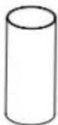
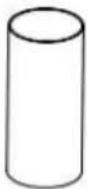
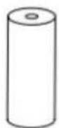
Technical line drawing of a mechanical device with cylindrical components and mounting base (no text or symbols)80-Grit Sanding Sleeves (6)
NOTE: 1/2" sanding sleeve fits directly on the spindle.
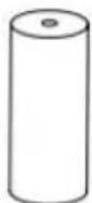
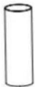
Rubber Sanding Drums (5)


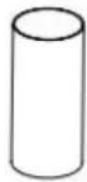
Sanding Throat Plates (6)

Flat Washer
D8(O.D. 14)

Flat Washer
D8(O.D. 16)
natural_image
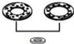
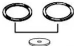
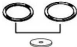
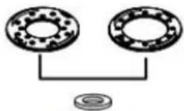
Simple line drawing of two circular components connected to a ball, no text or symbols presentBig Flat Washer D8 (O.D. 24)
natural_image
Simple line drawing of two circular rings connected to a central dot, with no text or symbols present.Sanding Drum Pressure Plate
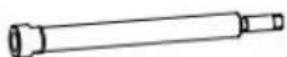
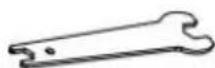
Driven Shaft

Wrench

Sanding Drum Pad

Spring Washer D8

Hex Nut M8

Spanner For The Spindle
OPERATING INSTRUCTIONS

WARNING!
INSTALLATION DES ACCESSOIRES NG!
natural_image
Technical line drawing of a mechanical device with cylindrical components and mounting base (no text or symbols)natural_image
Technical line drawing of a mechanical device with labeled components (no text or symbols present)FONCTIONNEMENT DE LA PONCEUSE À BROCHE
natural_image
Illustration of hands operating a rotating mechanical device with a rotating knob (no text or symbols)Lieu, Rancho Cucamonga, CA 91730
| UK | REP |
YH CONSULTING LIMITED. C/O YH Consultin Limited Office 147, Centurion House, London Road, Staines-upon-Thames, Surrey, TW18 4A>
| EC | REP |
Affordable. Reliable. Home Improvement.
SPINDELSCHLEIFER
MODELL: OSM-1
VEVOR
SPINDELSCHLEIFER
Affordable. Reliable. Home Improvement.
MODELL: OSM-1

natural_image
Technical line drawing of a mechanical device with no visible text or symbols80-Grit Sanding Sleeves (6)
NOTE: 1/2" sanding sleeve fits directly on the spindle.
Rubber Sanding Drums (5)


Sanding Throat Plates (6)

Flat Washer
D8(O.D. 14)

Flat Washer
D8(O.D. 16)

natural_image
Simple line drawing of two circular components connected to a base plate (no text or symbols)Big Flat Washer D8 (O.D. 24)
natural_image
Simple line drawing of two circular rings connected to a central dot, with no text or symbols present.Sanding Drum Pressure Plate

Driven Shaft

Wrench

Sanding Drum Pad

Spring Washer D8

Hex Nut M8

Spanner For The Spindle
OPERATING INSTRUCTIONS

WARNING!
INSTALLATION DES ZUBEHÖRS NG!
natural_image
Technical line drawing of a mechanical device with cylindrical components and mounting base (no text or symbols)natural_image
Technical line drawing of a mechanical device with labeled components (no text or symbols present)natural_image
Illustration of hands operating a rotating mechanical device with a rotating knob (no text or symbols)YH CONSULTING LIMITED. C/O YH Consultin Limited Office 147, Centurion House, London Road, Staines-upon-Thames, Surrey, TW18 4A>
| EC | REP |
Affordable. Reliable. Home Improvement.
LEVIGATRICE A
MANDRINO
MODELLO: OSM-1
MODELLO: OSM-1
natural_image
Technical line drawing of a mechanical device with cylindrical components and mounting base (no text or symbols)6. ACCESSORI PER LA LEVIGATURA
80-Grit Sanding Sleeves (6)
NOTE: 1/2" sanding sleeve fits directly on the spindle.
Rubber Sanding Drums (5)


Sanding Throat Plates (6)

Flat Washer
D8(O.D. 14)

Flat Washer
D8(O.D. 16)

natural_image
Diagram of two circular components connected by a string, with a base plate nearby (no text or symbols)Big Flat Washer D8 (O.D. 24)

natural_image
Simple line drawing of two circular rings connected to a central dot, with no text or symbols present.Sanding Drum Pressure Plate
Driven Shaft

Wrench

Sanding Drum Pad

Spring Washer D8

Hex Nut M8

Spanner For The Spindle
OPERATING INSTRUCTIONS

WARNING!
natural_image
Technical line drawing of a mechanical device with cylindrical components and mounting base (no text or symbols)natural_image
Technical line drawing of a mechanical device with labeled components (no text or symbols present)natural_image
Illustration of hands operating a rotating mechanical component with a rotating arrow (no text or symbols)velocità.
TROUBLESHOOTING GUIDE
AVVERTIMENTO!
YH CONSULTING LIMITED. C/O YH Consultin Limited Office 147, Centurion House, London Road, Staines-upon-Thames, Surrey, TW18 4A>
| EC | REP |
Affordable. Reliable. Home Improvement.
LIJADORA DE HUSILLO
MODELO: OSM-1
MODELO: OSM-1
natural_image
Technical line drawing of a mechanical device with cylindrical components and mounting base (no text or symbols)80-Grit Sanding Sleeves (6)
NOTE: 1/2" sanding sleeve fits directly on the spindle.
Rubber Sanding Drums (5)


Sanding Throat Plates (6)

Flat Washer
D8(O.D. 14)

Flat Washer
D8(O.D. 16)

natural_image
Diagram of two circular components connected by a horizontal line to a base plate (no text or symbols)Big Flat Washer D8 (O.D. 24)

natural_image
Simple line drawing of two circular rings connected to a central dot, with no text or symbols present.Sanding Drum Pressure Plate

Driven Shaft

Wrench

Sanding Drum Pad

Spring Washer D8

Hex Nut M8

Spanner For The Spindle
OPERATING INSTRUCTIONS

WARNING!
natural_image
Technical line drawing of a mechanical device with cylindrical components and mounting base (no text or symbols)natural_image
Technical line drawing of a mechanical device with labeled components (no text or symbols present)FUNCIONAMIENTO DE LA LIJADORA DE HUSILLO
natural_image
Illustration of hands operating a rotating mechanical device with a rotating wheel and directional arrows (no text or symbols)YH CONSULTING LIMITED. C/O YH Consultin Limited Office 147, Centurion House, London Road, Staines-upon-Thames, Surrey, TW18 4A>
| EC | REP |
Affordable. Reliable. Home Improvement.
natural_image
Technical line drawing of a mechanical device with no visible text or symbolsBEZPIECZEŃSTWO W MIEJSCU PRACY
bar
| Accessory | Size (mm) | Dimension | | --- | --- | --- | | 80-Grit Sanding Sleeves | 6 | - | | Rubber Sanding Drums | 5 | - | | Sanding Throat Plates | 6 | - | | Upper Spindle Washer Size | - | Flat Washer D8(O.D. 14) | | Sanding Drum Pressure Plate | - | Big Flat Washer D8 (O.D. 24) | | Driven Shaft | - | Wrench | | Wrench | - | Sanding Drum Pad | | Spring Washer D8 | - | Hex Nut M8 | | Spanner For The Spindle | - | - |OPERATING INSTRUCTIONS

WARNING!
MONTAŻ AKCESORIÓW NG!
natural_image
Technical line drawing of a mechanical device with cylindrical components and mounting base (no text or symbols)natural_image
Technical line drawing of a mechanical device with labeled components (no text or symbols present)OBSŁUGA SZLIFIERKI WRZECIONOWEJ
natural_image
Illustration of hands operating a rotating mechanical device with a rotating wheel (no text or symbols)YH CONSULTING LIMITED. C/O YH Consultin Limited Office 147, Centurion House, London Road, Staines-upon-Thames, Surrey, TW18 4A>
| EC | REP |
Affordable. Reliable. Home Improvement.
SPINDELSCHUURMACHIN
E
MODEL: OSM-1
MODEL: OSM-1

natural_image
Technical line drawing of a mechanical device with no visible text or symbolsWAARSCHUWING VOOR CALIFORNIË PROPOSITIE 65
80-Grit Sanding Sleeves (6)
NOTE: 1/2" sanding sleeve fits directly on the spindle.
Rubber Sanding Drums (5)


Sanding Throat Plates (6)

Flat Washer
D8(O.D. 14)

Flat Washer
D8(O.D. 16)
natural_image
Simple diagram showing two circular components connected to a ball, with no text or symbols present.Big Flat Washer D8 (O.D. 24)

natural_image
Simple line drawing of two circular rings connected to a central dot, with no text or symbols present.Sanding Drum Pressure Plate
Driven Shaft

Wrench

Sanding Drum Pad

Spring Washer D8

Hex Nut M8

Spanner For The Spindle
OPERATING INSTRUCTIONS

WARNING!
DE ACCESSOIRES INSTALLEREN NG!
MACHINE MONTAGE
BOVENSTE BESCHERMING

WARNING!
natural_image
Technical line drawing of a mechanical device with cylindrical components and mounting base (no text or symbols)natural_image
Technical line drawing of a mechanical device with labeled components (no text or symbols present)BEDIENING VAN DE SPINDELSCHUURMACHINE
natural_image
Illustration of hands operating a rotating mechanical device with a rotating wheel and directional arrows (no text or symbols)YH CONSULTING LIMITED. C/O YH Consultin Limited Office 147, Centurion House, London Road, Staines-upon-Thames, Surrey, TW18 4A>
| EC | REP |
Affordable. Reliable. Home Improvement.
SPINDELSLIPMASKIN
MODELL: OSM-1
VEVOR
Affordable. Reliable. Home Improvement.
SPINDELSLIPMASKIN
MODELL: OSM-1
natural_image
Technical line drawing of a mechanical device with no visible text or symbolsother
| Accessories | Size (mm) | Diameter | | --- | --- | --- | | 80-Grit Sanding Sleeves | 1/2" | 13 | | 80-Grit Sanding Sleeves | 3/4" | 19 | | 80-Grit Sanding Sleeves | 1" | 26 | | 80-Grit Sanding Sleeves | 1-1/2" | 38 | | 80-Grit Sanding Sleeves | 2" | 51 | | 80-Grit Sanding Sleeves | 3" | 76 | | Rubber Sanding Drums | 5 | | | Sanding Throat Plates | 6 | | | Upper Spindle Washer Size | Flat Washer D8(O.D. 14) | | | Upper Spindle Washer Size | Flat Washer D8(O.D. 16) | | | Upper Spindle Washer Size | Big Flat Washer D8 (O.D. 24) | | | Sanding Drum Pressure Plate | | |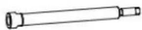
Driven Shaft
Wrench

Sanding Drum Pad

Spring Washer D8

Hex Nut M8

Spanner For The Spindle
OPERATING INSTRUCTIONS

WARNING!
MONTERING AV TILLBEHÖR NG!
planbricka D8 (1).
natural_image
Technical line drawing of a mechanical device with cylindrical components and mounting base (no text or symbols)natural_image
Technical line drawing of a mechanical device with labeled components (no text or symbols present)natural_image
Illustration of hands operating a rotating mechanical device with a rotating shaft and directional arrows (no text or symbols)TROUBLESHOOTING GUIDE
WARNING!
YH CONSULTING LIMITED. C/O YH Consultin Limited Office 147, Centurion House, London Road, Staines-upon-Thames, Surrey, TW18 4A>
| EC | REP |