
RFS-065 - Engraving machine Vevor - Free user manual and instructions
Find the device manual for free RFS-065 Vevor in PDF.



| Product Type | Line marking machine (ground line marker) |
| Brand | Vevor |
| Model | RFS-065 / RFS-050 |
| Adjustable line width | 2 inches (50 mm) or 4 inches (100 mm) via speed lever |
| Recommended pulling speed | 0.15 m/s |
| Approximate weight | 5 kg (estimated) |
| Package dimensions | Not specified in the manual |
| Power supply | Manual (non-motorized tool) |
| Material | Steel and plastic |
| Components | Main frame, wheels (4), axles, springs, powder deflector, mixer, armrest, speed lever |
| Main function | Draw straight lines on the ground (powder or paint) |
| Maintenance and cleaning | Clean the ground before use; keep the machine dry; remove powder after use |
| Safety | Read the manual before use; do not use as a toy; keep out of reach of children; avoid open flames and sharp objects |
| Spare parts | Wheels, springs, washers, axles, screws, cotter pins, speed lever, armrest |
| Repairability | Parts available via after-sales service (www.vevor.com/support) |
| Warranty | Electronic warranty certificate available online |
| User manual | Available in multiple languages (FR, DE, EN, IT, NL, PL, SV) |
| Technical support | www.vevor.com/support |
Frequently Asked Questions - RFS-065 Vevor
User questions about RFS-065 Vevor
0 question about this device. Answer the ones you know or ask your own.
Ask a new question about this device
Download the instructions for your Engraving machine in PDF format for free! Find your manual RFS-065 - Vevor and take your electronic device back in hand. On this page are published all the documents necessary for the use of your device. RFS-065 by Vevor.
USER MANUAL RFS-065 Vevor
LINE SCRIBING MACHINE
RFS-065/RFS-050
We continue to be committed to provide you tools with competitive price.
"Save Half", "Half Price" or any other similar expressions used by us only represents estimate of savings you might benefit from buying certain tools with us compared to the brands and does not necessarily mean to cover all categories of tools offered by us. You are kindly reminded to verify carefully when you are placing an order with us if you are actually saving half in comparison with the top major brands.
VEVOR®
TOUGH TOOLS, HALF PRICE
RFS-065/RFS-050
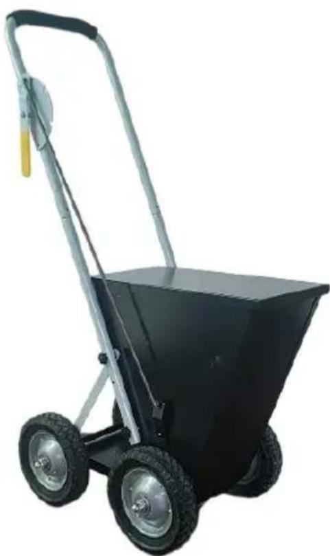
(The picture is for reference only; please refer to the actual object)
NEED HELP? CONTACT US!
Have product questions? Need technical support? Please feel free to contact Technical Support and E-Warranty Certificate www.vevor.com/support
This is the original instruction. Please read all manual instructions carefully before operating. VEVOR reserves a clear interpretation of our user manual. The appearance of the product shall be subject to the product you received. Please forgive us that we won't inform you again if there are any technology or software updates on our product.
| Symbol | Symbol Description |
 | Warning: To reduce the risk of injury, the user must read the instructions manual carefully. |
 | This symbol, placed before a safety comment, indicates a precaution, warning, or danger. Ignoring this warning may an accident. To reduce the risk of injury, fire, or electro please always follow the recommendations shown below. |

WARNING: To reduce the risk of injury, the user must read the
instructions manual carefully.
- Use as intended only. The product is not a toy, and it cannot be played by children to prevent children from hurting themselves by mistake.
- The product cannot be used to injure people maliciously.
- Keep away from open flame.
- Keep away from sharp points, blades and other items, so as not to scratch the product.
SAVE THESE INSTRUCTIONS
PART LIST
| ITEM | QTY | PIC | ITEM | QTY | PIC |
| A-User manual | 1 |  | J-wheel | 4 | 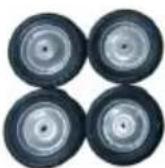 |
| B-M6x35 screws | 6 | 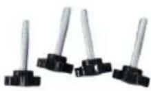 | K-support pole | 2 | 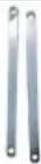 |
| C-gear lever | 1 | L-armrest (including pre-installed control module) | 1 | 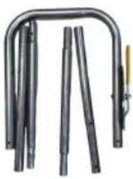 | |
| D-split pin | 3 |  | M-armrest link | 4 | |
| E-M4x12 screws | 2 | 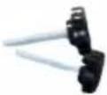 | N-wheel axle | 2 | |
| F-cover | 1 |  | O-mixer | 1 | 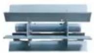 |
| G-short spring | 4 | 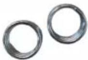 | P-powder baffle | 1 | 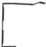 |
| H-gasket | 8 | 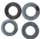 | Q-main framework | 1 | 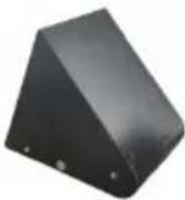 |
| I-M12x12 round head nut | 4 | 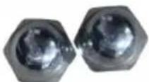 |
(The picture is for reference only; please refer to the actual object)
INSTALLATION
STEP1: Install the wheels
Prepare the following items.
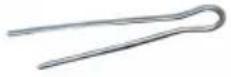 | 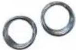 | 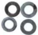 | 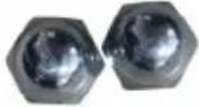 | 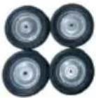 |
| D-split pin*2 | G-short spring*4 | H-gasket*8 | I-M12x12 round head nut*4 | J-wheel*4 |
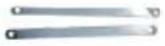 |  | 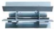 |  |  |
| K-support pole*2 | N-wheel axle*2 | O-mixer*1 | P-powder baffle*1 | Q-main framework*1 |
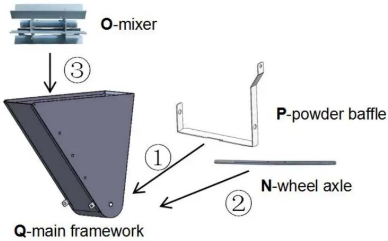
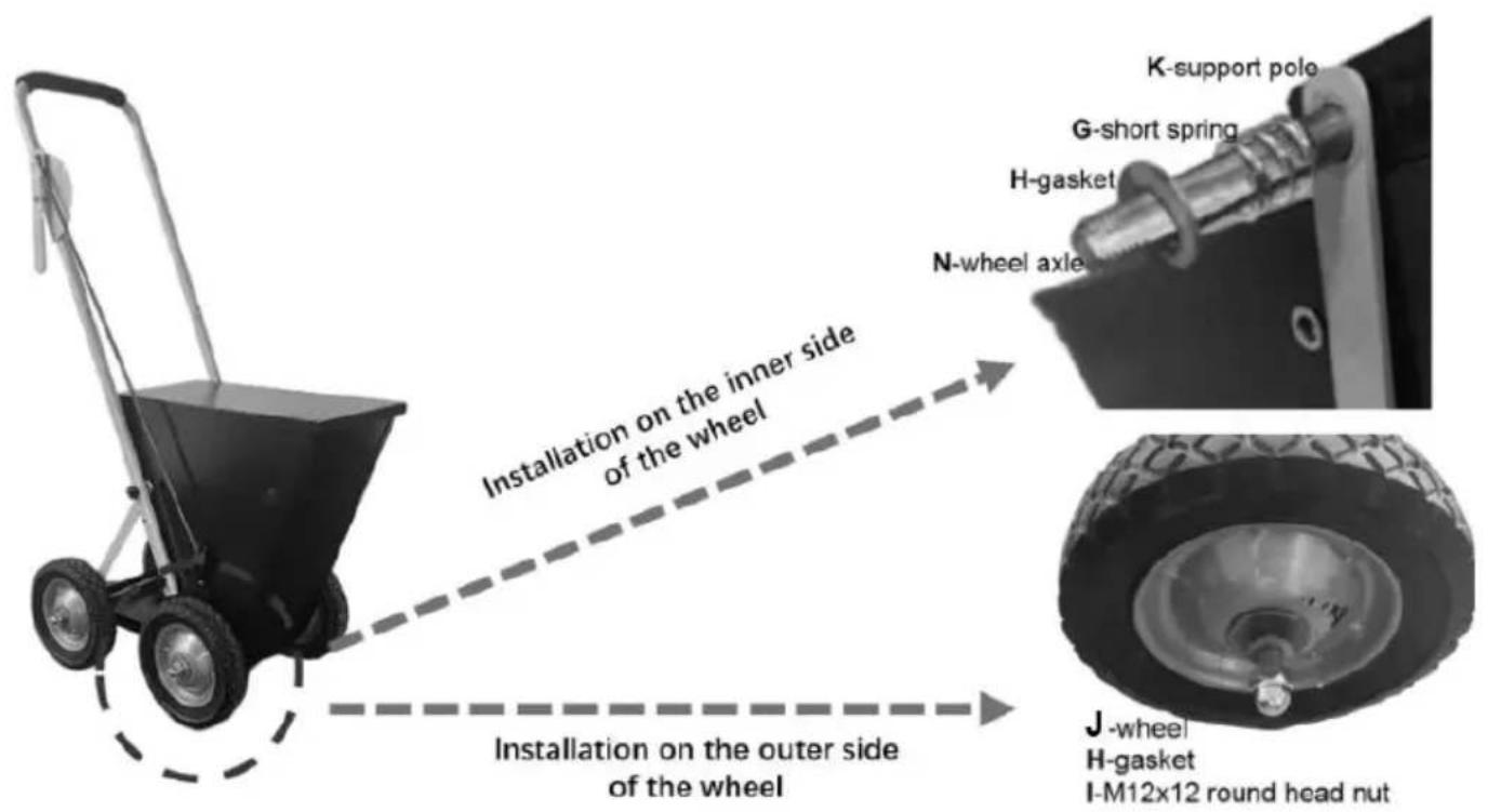
Firstly, align the holes of the P-powder shuffle and Q-main framework. Paying attention to the orientation of the P-powder baffle as shown in the figure. Then thread the N-wheel axle through the P-powder baffle, Q-main framework, and O-mixer in sequence.
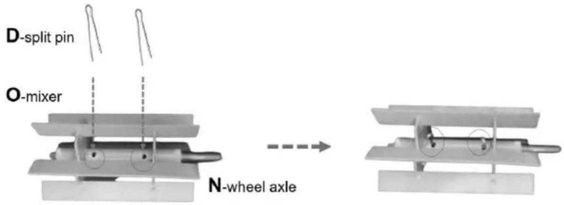
Align the holes of the O-mixer and N-wheel axle, and then insert the D-split pin. Fold the split pin if necessary.
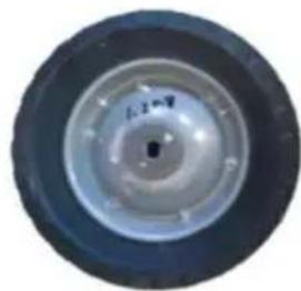
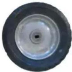
Install one K-support pole, one G-short spring, one H-gasket, one J-wheel, and one H-gasket into one side of the axle in order, and then lock them with I-M12 nut. Pay attention to the orientation of the J-wheel. Repeat the steps for another The steps for the rest wheels are similar (not having the O-mixer and K-support pole).
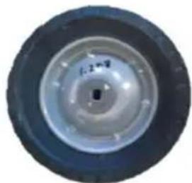
Outward have a drum shape
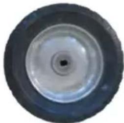
Inward Concave in shape
STEP2: Install the cover
Prepare the following items.
F-cover*1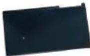
E-M4x12 screws*2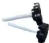
Installed parts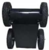
Align the holes on the F-cover and Q-main framework, and tighten them with E-M4x12 screws.
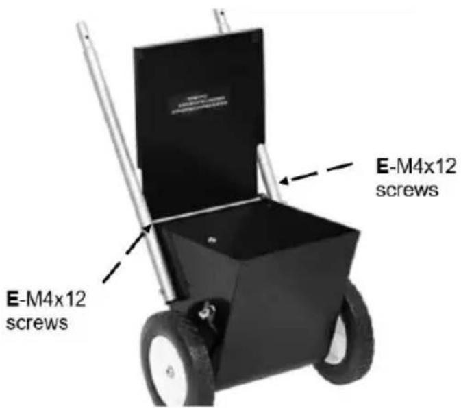
STEP3: Install the adjustment component. Prepare the following items.
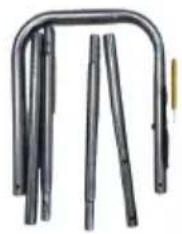
L-armrest (including pre-installed control module), B-M6x35 screws*6
M-armrest link*4
C-gear lever*1
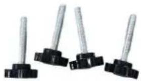
B-M6x35 screws*6
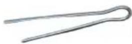
D-split pin*1
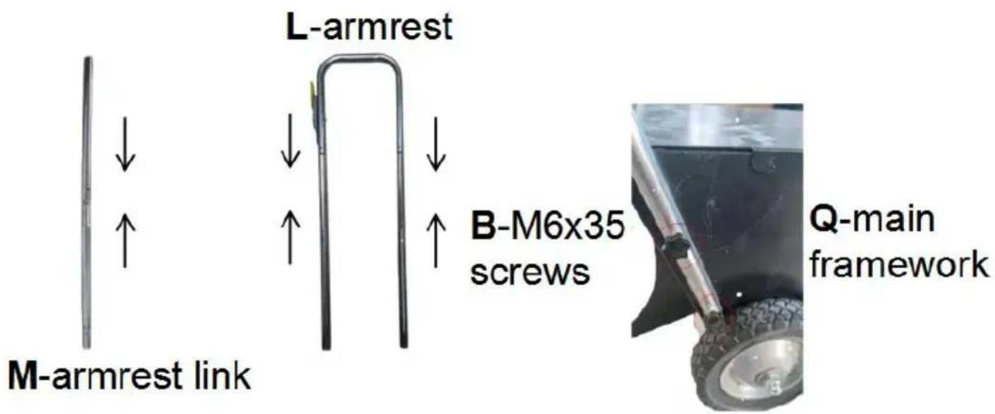
Connect the M-armrest links in pairs and then connect them to the L-armrest. Align the holes of the M-armrest links, K-support pole, and Q-main framework, and tighten them with B-M6x35 screws.
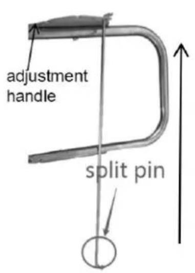
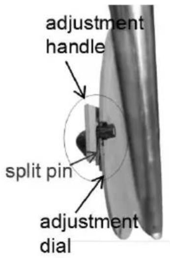
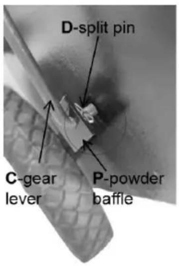
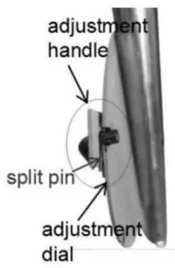
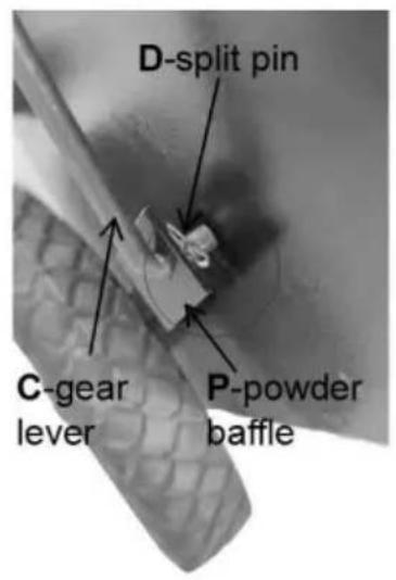
Insert the C-gear lever without a pin into the hole of the adjustment handle, clamp the pin between the adjustment handle and the adjustment dial. Then, insert the C-gear lever into the hole of the P-powder baffle and fix it with the D-split pin.
STEP4: Adjust the line width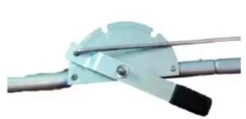
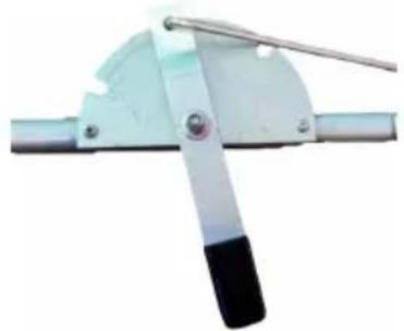
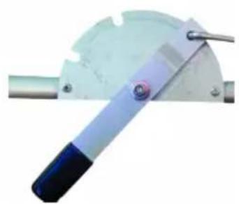
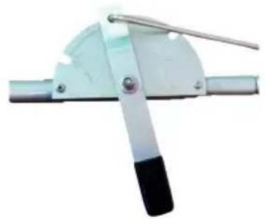
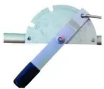
As shown in the figure, there are three gears (off, 2", 4") on the adjustment. Insert the gear lever into different positions to obtain the corresponding line width.
TIPS
- Before line striping, make sure to clean the ground and keep it dry.
- The effect is related to the forward speed. We recommend a forward speed of 0.15 m/s. Adjustments can be made according to the actual situation.
VEVOR®
TOUGH TOOLS, HALF PRICE
Technical Support and E-Warranty Certificate www.vevor.com/support
VEVOR®
TOUGH TOOLS, HALF PRICE
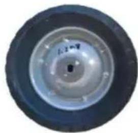
Outward have a drum shape
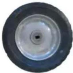
Inward Concave in shape
Perno diviso a D*1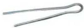
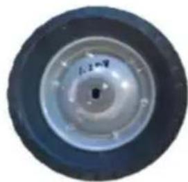
Outward have a drum shape
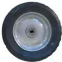
Inward Concave in shape
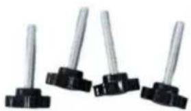
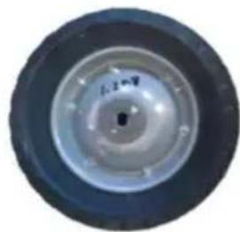
Outward have a drum shape
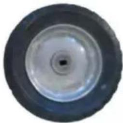
Inward Concave in shape
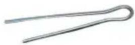
D-split pin*1
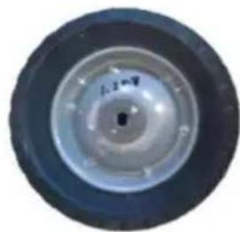
Outward have a drum shape
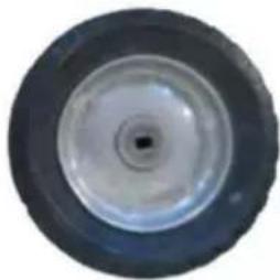
Inward Concave in shape
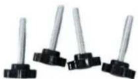
Q-main framework
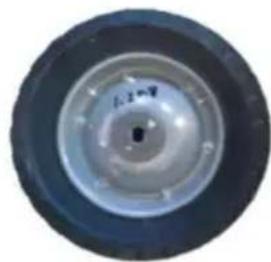
Outward have a drum shape
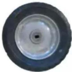
Inward Concave in shape
STEP 2: Install the cover
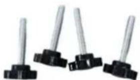
Q-main framework
Outward have a drum shape
Inward Concave in shape
STEP 2: Install the cover
D-split pin*1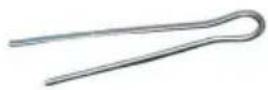
STEP 4: Adjust the line width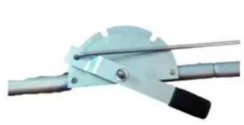
Q-main framework
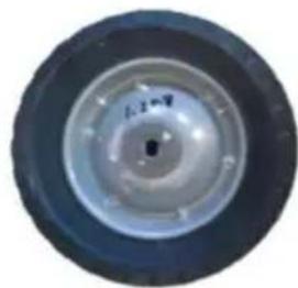
Outward have a drum shape
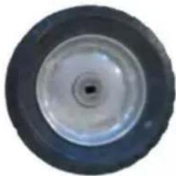
Inward Concave in shape
STEP 2: Install the cover
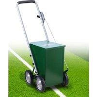
Brand : Vevor
Model : RFS-065
Category : Engraving machine