LAN255 - Outboard motor Vevor - Free user manual and instructions
Find the device manual for free LAN255 Vevor in PDF.

| Product Type | Trolling Motor Electric |
| Brand | Vevor |
| Model | LAN255 (also LAN155) |
| Maximum Thrust | 55 lb (approx. 25 kg) |
| Supply Voltage | 12 V DC |
| Maximum Current | 50 A |
| Recommended Battery Type | 12V marine deep cycle battery, minimum 60 Ah |
| Required Protection Device | 60 A circuit breaker or fuse @ 12 V DC |
| Recommended Cable Gauge | 8 AWG (up to 15 ft), 6 AWG (up to 20 ft) |
| Speed Control | Rotary handle with forward/reverse and OFF |
| Direction | Manual with adjustable tension knob |
| Minimum Immersion Depth | 12 inches (30 cm) below surface |
| Battery Indicator | LED lights (2-3 lights indicate 10 minutes reserve) |
| Tilt | Quick release lever for shallow water or storage |
| Shaft Material | Composite (periodic cleaning and lubrication recommended) |
| Propeller | Replaceable, nut torque 25-35 inch-pounds |
| Sound Level | Below 70 dB(A) |
| Vibration Level | Below 2.5 m/s² |
| Operating Temperature | -10 °C to 50 °C |
| Operating Humidity | 5% to 95% |
| Maximum Altitude | 10,000 ft (3,048 m) |
| Post-Use Maintenance | Freshwater rinse, silicone spray, check propeller nut |
| Warranty | Electronic warranty certificate at www.vevor.com/support |
Frequently Asked Questions - LAN255 Vevor
User questions about LAN255 Vevor
0 question about this device. Answer the ones you know or ask your own.
Ask a new question about this device
Download the instructions for your Outboard motor in PDF format for free! Find your manual LAN255 - Vevor and take your electronic device back in hand. On this page are published all the documents necessary for the use of your device. LAN255 by Vevor.
USER MANUAL LAN255 Vevor
Technical Support and E-Warranty Certificate www.vevor.com/support
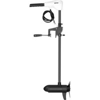
Electric Trolling Motor
Model:LAN155/LAN255
We continue to be committed to provide you tools with competitive price. "Save Half", "Half Price" or any other similar expressions used by us only represents an estimate of savings you might benefit from buying certain tools with us compared to the major top brands and does not necessarily mean to co all categories of tools offered by us. You are kindly reminded to verify carefully when you are placing an order with us if you are actually Saving Half in comparison with the top major brands.
Model:LAN155/LAN255
NEED HELP? CONTACT US!
Have product questions? Need technical support? Please feel free to contact us:
Technical Support and E-Warranty Certificate www.vevor.com/support
This is the original instruction, please read all manual instructions care before operating. VEVOR reserves a clear interpretation of our user manual. The appearance of the product shall be subject to the produ received. Please forgive us that we won't inform you again if there a technology or software updates on our product.
CORRECT DISPOSAL

This product is subject to the provision of European Directive 2012/19/EU.
The symbol showing a wheelie bin crossed through indicates that
the product requires separate refuse collection in the European Union.
This applies to the product and all accessories marked with this symbol. Products marked as such may not be discarded with normal domestic waste but must be taken to a collection point for recycling electrical and electro devices.
FCC Information:
CAUTION: Changes or modifications not expressly approved by the party responsible for compliance could void the user's authority to operate the equipment!
This device complies with Part 15 of the FCC Rules. Operation is subject to the following two conditions:
1) This product may cause harmful interference.
2) This product must accept any interference received, including interference that may cause undesired operation.
WARNING: Changes or modifications to this product not expressly approved by the party.
responsible for compliance could void the user's authority to operate the product.
Note: This product has been tested and found to comply with the limits Class B digital device pursuant to Part 15 of the FCC Rules, These limits are designed to provide reasonable protection against harmful
interference in a residential installation.
This product generates, uses and can radiate radio frequency energy, and not installed and used in accordance with the instructions, may cause harmful interference to radio communications. However, there is no guarantee that interference will not occur in a particular installation. If this product does cause harmful interference to radio or television reception, which can be determined by turning the product off and on, the user is encouraged to try to correct the interference by one or more of the following measures.
Reorient or relocate the receiving antenna.
Increase the distance between the product and receiver.
-
Connect the product to an outlet on a circuit different from that to which the receiver is connected.
-
Consult the dealer or an experienced radio/TV technician for assistance.
SAFETYCONSIDERATIONS
Please thoroughly read the user manual. Follow all instructions and heed all safety and cautionary notices. Use of this motor is only permitted for persons that have read and understood these user instructions. Minors may use this motor only under adult supervision.
WARNING!
You are responsible for the safe and prudent operation of your vessel. We have designed your VEVOR product to be an accurate and reliable tool that will enhance boat operation and improve your ability to catch fish. This product does not relieve you from the responsibility for safe operation of your boat. You may avoid hazards to navigation and always maintain a permanent watch so you respond to situations as they develop. You must always be prepared to rega manual control of your boat. Learn to operate your VEVOR product in an ar free from hazards and obstacles.
WARNING!
Never run the motor out of the water, as this may result in injuries from the
rotating propeller, The motor should be disconnected fro the power source wh. it is not in use or is off the water. When connecting the power-supply cable the motor to the battery, ensure that they are not kinked or subject to chafe route them in such a way that persons cannot trip over them. Before using motor make sure that the insulation of the power cables is not damaged. Disregarding these safety precautions may result in electric short of battery(s) and/or motor. Always disconnect motor from battery(s) before cleaning or checking the propeller. Avoid submerging the complete motor as water may enter the lower unit through control head and shaft. If the motor is used wh water is present in the lower unit considerable damage to the motor can occur. This damage will not be covered by warranty.
WARNING!
Take care that neither you nor other persons approach the turning propeller is closely, neither with body parts nor with object. The motor is powerful and may endanger or injure you or others. While the motor is running watch out for persons swimming and for floating objects. Persons who lack the ability to run the motor or whose reactions are impaired by alcohol, drugs, medication, or other substances are not permitted to use this motor. This motor is not suitable for use in strong currents. The constant noise pressure level of the motor du use is less than 70dB(A). The overall vibration level does not exceed 2,5 m/sec2.
WARNING!
When stowing or deploying the motor, keep fingers clear of all hinge and pin points and all moving parts. In the event of unexpected operation, remove power leads from the battery
WARNING!
It is recommended to only use VEVOR approved accessories with your VEVC motor. Using non-approved accessories including to mount or control your motor may cause damage, unexpected motor operation and injury. Be sure to use the product and approved accessories, including remotes, safely and in the manner directed to avoid accidental or unexpected motor operation. Keep all
factory installed parts in place including motor and accessory covers, enclosures and guards
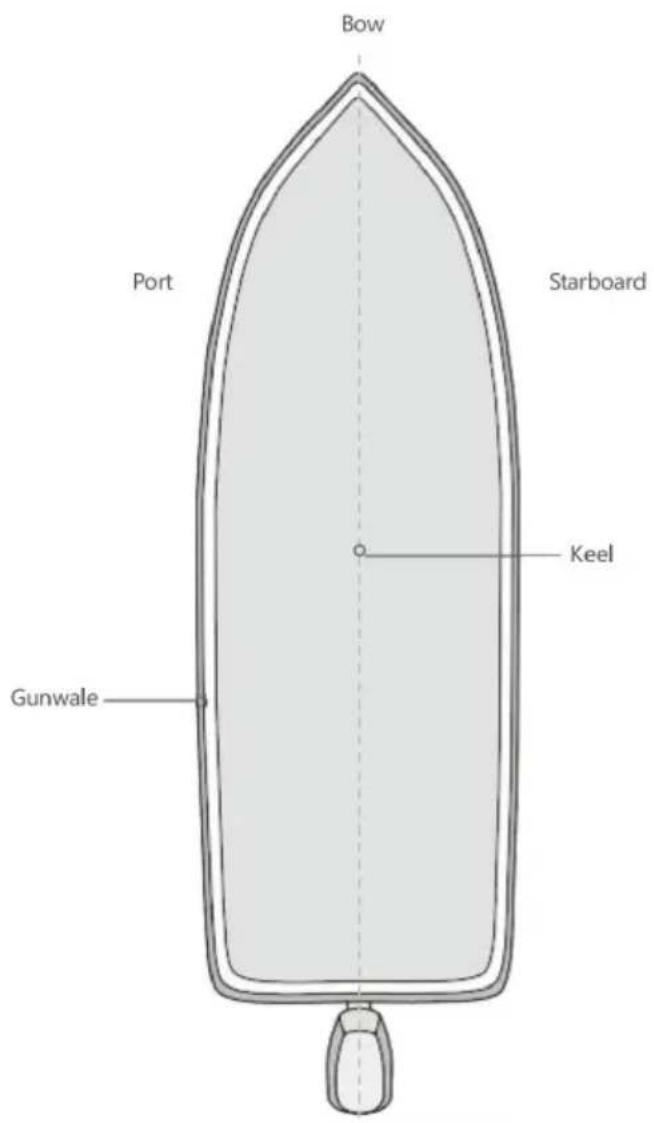
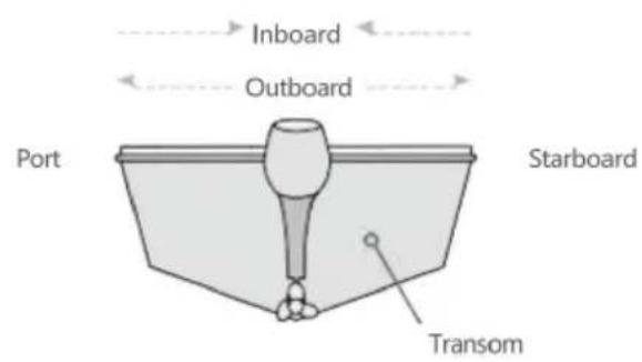
SHIP INFORMATION
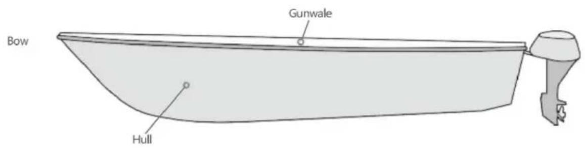
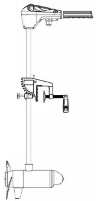
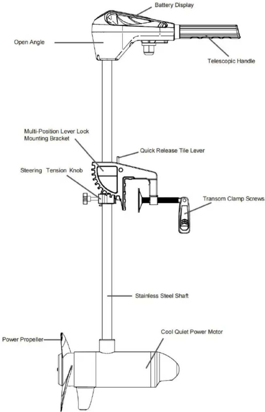
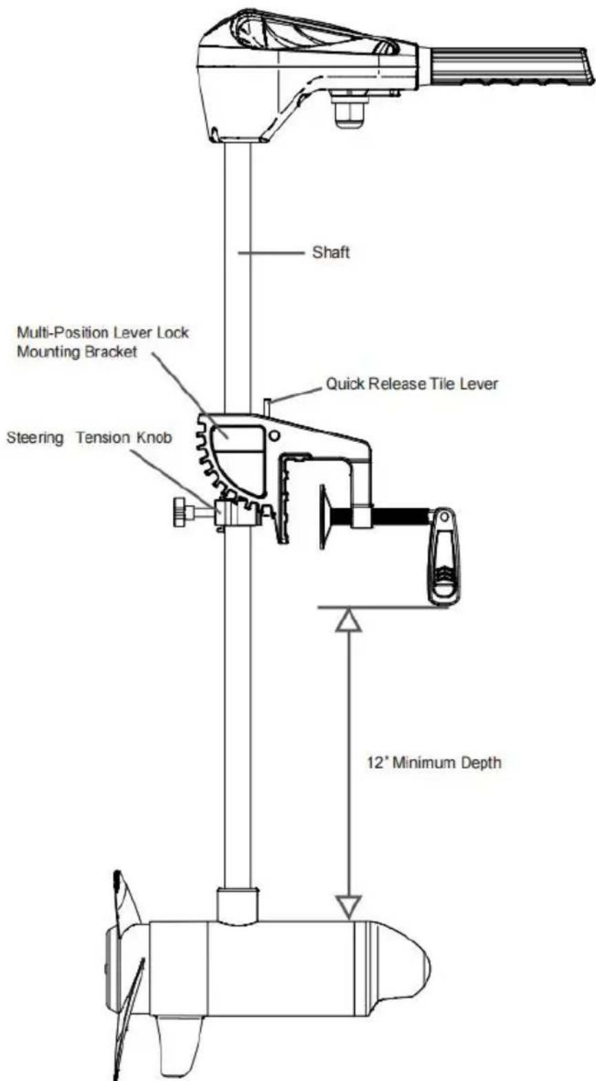
FEATURES
NOTICE: Specifications subject to change without notice. This diagram is for reference only and may differ from your actual motor.
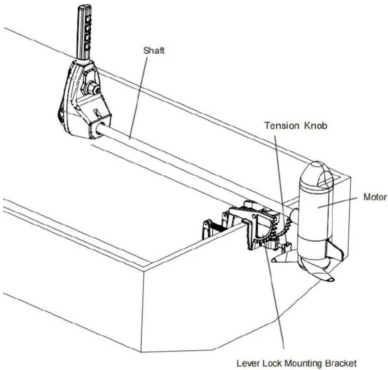
INSTALLATION
Motor Installation
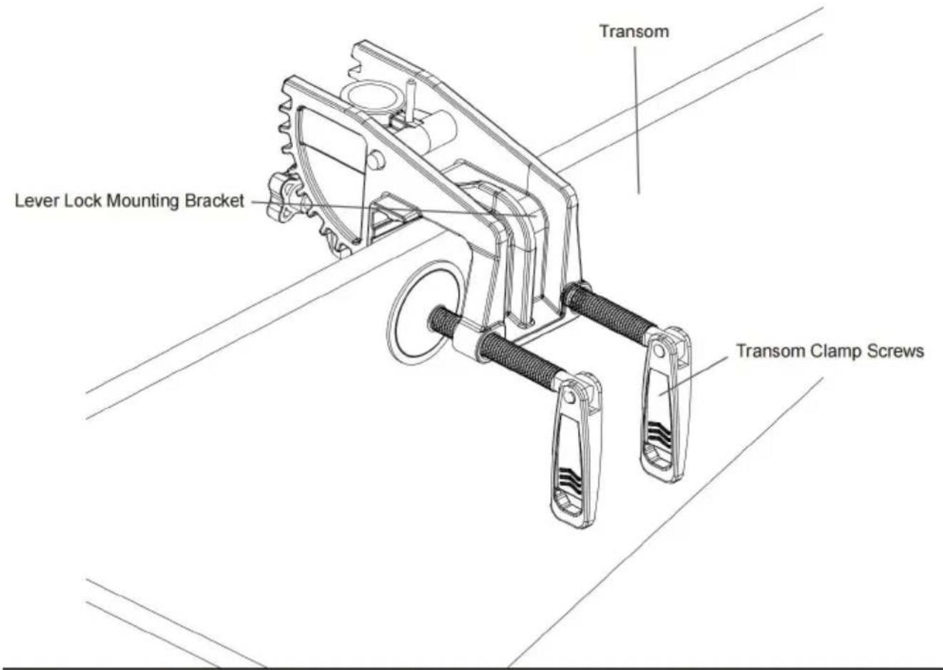
a.Find a transom area of the boat that is free from obstructions.
b. Open the Transom Clamp Screws on the bracket enough so that it will be the top of the boat transom.
c. Place the Lever Lock Mounting Bracket over the top of the boat transom the bracket is resting on top of the transom.
d. Verify that there are no obstacles that the control box, handle, or prop m while in use that would restrict steering or cause damage to the motor.
e. Tighten down the Transom Clamp Screws to the transom by hand only. I use any tools to tighten the clamp screws as this may damage the bracket or your boat.
CAUTION
Over-tightening the Transom Clamp Screws can damage the bracket. Damage to the bracket will prevent the motor from being securely mo to the transom. Prevent damage to the bracket by not over-tightening Only tighten by hand.
f. We recommend the tilt angle of the motor to be adjusted so that motor shaft is perpendicular to the water surface when the motor is
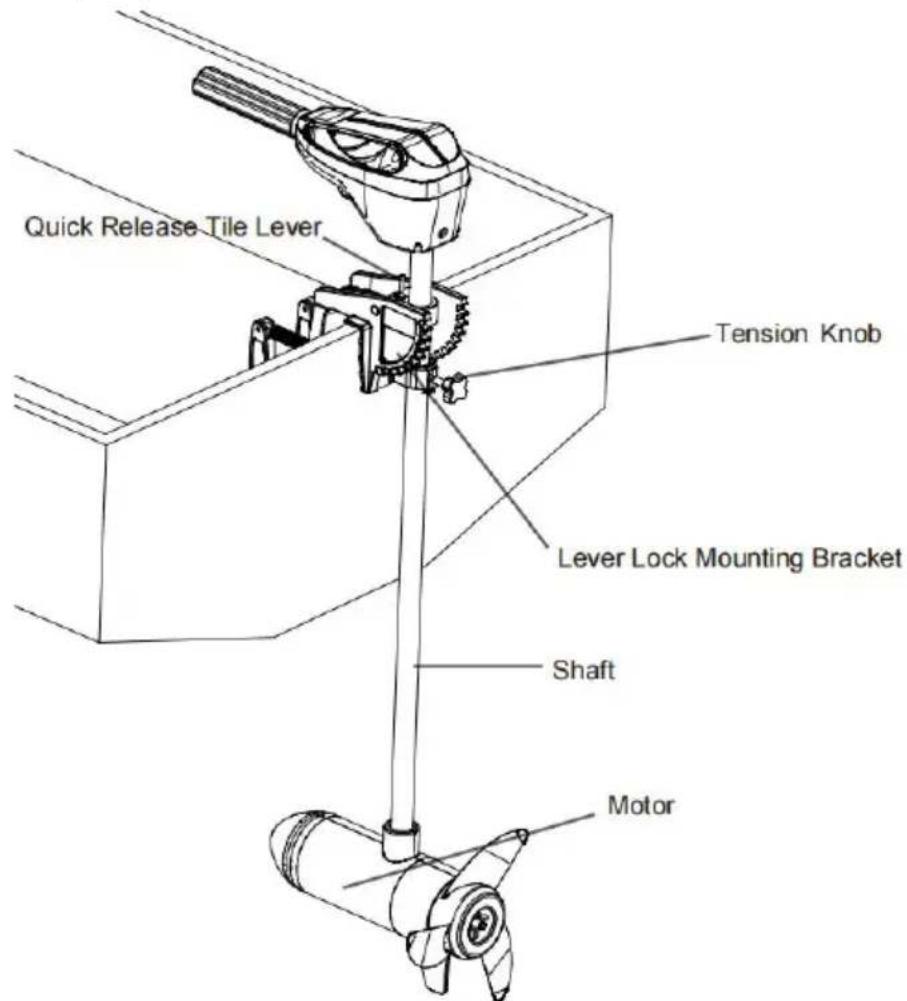
g. For transport, always tilt the motor into the boat, such that the m prop assembly are completely out of the water and the motor is pos up close to the Lever Lock Mounting Bracket.
WARNING
When the motor is being transported, on water or land, it is important to place motor completely out of water. The motor should be positioned up close to the Lever Lock Mounting Bracket. Always secure the Steering Tension Knob and the Adjustable Depth Collar down to the top of the Steering Tension Knob for added security during transport. This provides a secure stow and holds the n in place during transportation when it is subject to high levels of shock and vibration. Failure to secure the motor may result in injury or damage to the
BATTERY &WIRING INSTALLATION
1. BOAT RIGGING & PRODUCT INSTALLATION
For safety and compliance reasons, we recommend that you follow American and Yacht Council (ABYC) standards when rigging
your boat. Altering boat wiring should be completed by a qualified marine technician. The following specifications are for general guidelines only:
CAUTION
These guidelines apply to general rigging to support your Minn Kota motor. Powering multiple motors or additional electrical devices from the same power circuit may impact the recommended conductor gauge and circuit breaker size you are using wire longer than that provided with your unit, follow the condugaue and circuit breaker sizing table below. If your wire extension length is than 25 feet, we recommend that you contact a qualified marine technician.
CAUTION
An over-current protection device (circuit breaker or fuse) must be used. Coast Guard requirements dictate that each ungrounded current-carrying conductor must be protected by a manually reset, trip-free circuit breaker or fuse. The (voltage and current rating) of the fuse or circuit breaker must be sized acc to the trolling motor used. The table below gives recommended guidelines for circuit breaker sizing.
CONDUCTOR GAUGE AND CIRCUIT BREAKER SIZING TABLE
This conductor and circuit breaker sizing table is only valid for the following assumptions:
- No more than 2 conductors are bundled together inside of a sheath or c outside of engine spaces.
- Each conductor has 105^ C temp rated insulation.
- No more than 5% voltage drop allowed at full motor power based on pul product power requirements.
| Motor Thrust/Mode | Max Amp Draw | Circuit Breaker | Wire Extension Length | ||||
| 5 feet | 10 feet | 15 feet | 20 feet | 25 feet | |||
| 30 lb. | 30 | 50Amp @12VDC | 10 AWG | 10 AWG | 8 AWG | 6 AWG | 4AWG |
| 40 lb.,451b | 42 | 10 AWG | 8 AWG | 6 AWG | 4 AWG | 4 AWG | |
| 50 lb.,55 lb | 50 | 60 Amp @12VDC | 8 AWG | 6 AWG | 4 AWG | 4AWG | 2 AWG |
| 70 lb. | 42 | 50 Amp @24VDC | 10 AWG | 10 AWG | 8 AWG | 8 AWG | 6 AWG |
| 80 lb. | 56 | 60 Amp @24VDC | 8 AWG | 8 AWG | 8 AWG | 6 AWG | 6 AWG |
| 101lb. | 46 | 50 Amp @36VDC | 8 AWG | 8 AWG | 8 AWG | 8 AWG | 8 AWG |
| Engine Mount 101 | 50 | 60 Amp @36VDC | 8 AWG | 8 AWG | 8 AWG | 8 AWG | 8 AWG |
| 112lb. | 52 | 60 Amp @36VDC | 8 AWG | 8 AWG | 8 AWG | 8 AWG | 8 AWG |
| Engine Mount 160 | 116 | 60 Amp @24VDC | 6 AWG | 6 AWG | 4 AWG | 2 AWG | 2 AWG |
| E-Driv | 40 | 50 Amp @48VDC | 10 AWG | 10 AWG | 10 AWG | 10 AWG | 10 AWG |
NOTICE: Wire Extension Length refers to the distance from the batteries to the trolling motor leads. Consult website for available thrust options. Maximum Amplitude Draw values only occur intermittently during select conditions and should not be used as continuous amp load ratings.
Reference United States Code of Federal Regulations: 33 CFR 183 - Boats & Associated Equipment ABYC E-11: AC and DC Electrical Systems on Boats.
SELECTING THE CORRECT BATTERIES
The motor will operate with any lead acid, deep cycle marine 12 volt battery/batteries. For best results, use a deep cycle, marine battery with at least 60 amp-hour rating. Maintain battery at full charge. Proper care will ensure the battery power when you need it and will significantly improve the battery life. Failure to recharge lead-acid batteries (within 12-24 hours) is the leading cause of premature battery failure. Use a multi-stage charger to avoid overcharging. We offer a wide selection of chargers to fit your charging needs. If you are using crank battery to start a gasoline outboard, we recommend that you use a set of deep cycle marine battery/batteries for your VEVOR trolling motor. For more information on battery selection and rigging, please check with related departments.
WARNING
Never connect the (+) and the (-) terminals of the same battery together. That no metal object can fall onto the battery and short the terminals. This is immediately lead to a short and extreme fire danger.
CAUTION
Refer to "Conductor Gauge and Circuit Breaker Sizing Table" in the previous section to find the appropriate circuit breaker or fuse for your motor.
CAUTION
Please read the following information before connecting your motor to your batteries in order to avoid damaging your motor and/or voiding your warranty.
ADDITIONAL CONSIDERATIONS
1. Using DC or Alternator Chargers
Your VEVOR trolling motor may be designed with an internal bonding wire to reduce sonar interference. Most alternator charging systems do not account for this bonding wire, and connect the negative posts of the trolling motor batteri the negative posts of the crank/starting battery. These external connections ca damage connected electronics and the electrical system of your trolling motor, voiding your warranty. Review your charger's manual carefully or consult the manufacturer prior to use to ensure your charger is compatible.
- Additional Accessories Connected to Trolling Motor Batteries Significant damage to your VEVOR motor, your boat electronics, and your boar can occur if incorrect connections are made between your trolling motor batte and other battery systems. VEVOR recommends using an exclusive battery system for your trolling motor. Where possible, accessories should be connecto a separate battery system. Radios and sonar units should not be connecte any trolling motor battery systems as interference from the trolling motor is unavoidable. If connecting any additional accessories to any trolling motor batt system, or making connections between the trolling motor batteries and other battery systems on the boat, be sure to carefully observe the information below
3. CONNECTING THE BATTERIES
The negative (-) connection must be connected to the negative terminal of the same battery that the trolling motor negative lead connects to. In the diagram below this battery is labeled "Low Side" Battery. Connecting to any other troll motor battery will input positive voltage into the "ground" of that accessory, we can cause excess corrosion. Any damage caused by incorrect connections Between battery systems will not be covered under warranty.
4. Automatic Jump Start Systems and Selector Switches
Automatic jump start systems and selector switches tie the negatives of the connected batteries together. Connecting these systems to the "High Side" Battery or "Middle" Battery in the diagrams below and will cause significant damage your trolling motor and electronics. The only trolling motor battery that is safe connect to one of these systems is the "Low Side" Battery.
5. 12/24 Volt Systems
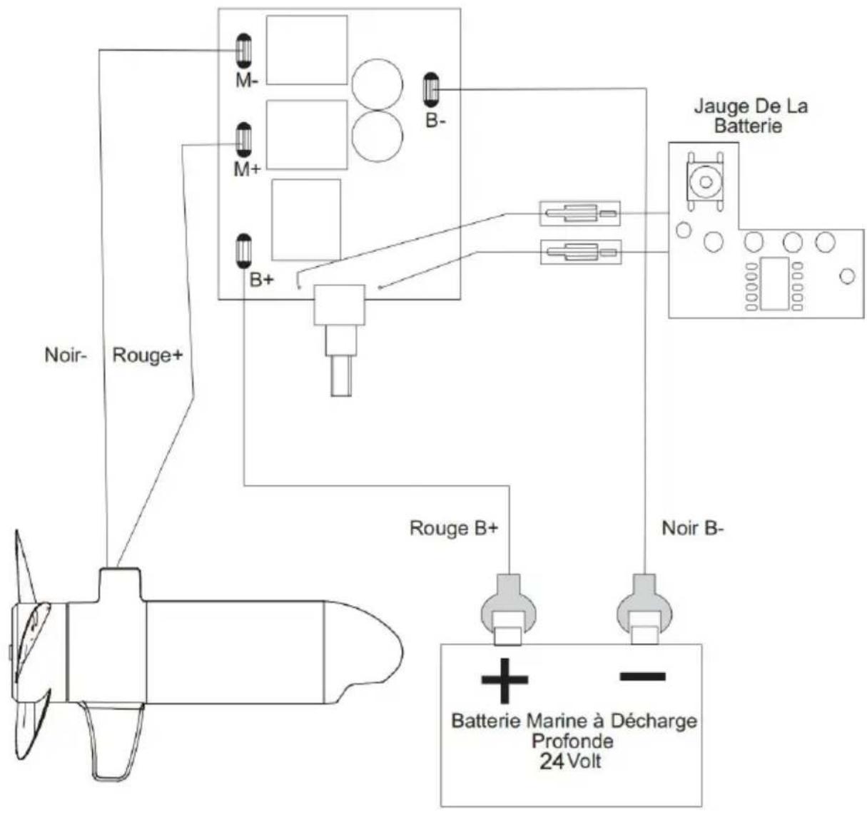
- Make sure that the motor is switched off (speed selector on "OFF" or "0")
- Connect positive (+) red lead to positive (+) battery terminal.
- Connect negative (-) black lead to negative (-) battery terminal.
WARNING
For safety reasons do not switch the motor on until the propeller is in the 'installing a leadwire plug, observe proper polarity and follow instructions in yo
boat owners manual.
WARNING
- For safety reasons, disconnect the motor from the battery or batteries when motor is not in use or while the battery/batteries are being charged.
- Improper wiring of 12/24 volt systems could cause battery explosion.
- Keep lead wire wing nut connections tight and solid to battery terminals.
- Locate battery in a ventilated compartment.
MOTOR WIRING DIAGRAM
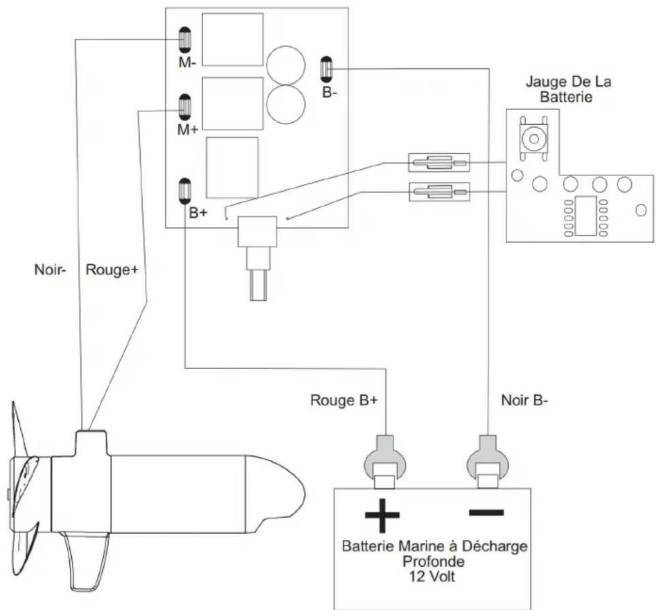
LAN155 MOTOR WIRING DIAGRAM
LAN255 MOTOR WIRING DIAGRAM
USING & ADJUSTING THE MOTOR
WARNING
When stowing or deploying the motor, keep fingers clear of all hinge and pin points and all moving parts. Practice proper ergonomics when stowing and deploying the motor to prevent injury.
WARNING
Moving the motor creates a variety of pinch points. The motor head will create pinch point if the Steering Tension Knob is loosened and the motor head slit the top of the Adjustable Depth Collar. Grasp the Shaft and prevent it from all the way down to prevent the pinch point. When adjusting the Mounting B by engaging the Quick Release Tilt Lever, watch for pinch points on the Lev
Lock Mounting Bracket and between the Shaft and Mounting Bracket. Grasp 1 motor away from the area that may come in contact with another area of tr to prevent injury. Watch for pinch points on the Tiller when moving the motc using the telescoping handle.
WARNING
When the motor is being transported, on water or land, it is important to plan motor completely out of water. The motor should be positioned up close to the Lever Lock Mounting Bracket. Always secure the Steering Tension Knob and the Adjustable Depth Collar down to the top of the Steering Tension Knob for added security during transport. This provides a secure stow and holds the n in place during transportation when it is subject to high levels of shock and vibration. Failure to secure the motor may result in injury or damage to the
1. STOWING THE MOTOR
a. Adjust depth so that the motor is fully raised.
b. Press and hold the Quick Release Tilt Lever.
c. Tilt motor into the boat.
d. For transport, always tilt the motor into the boat such that the motor and assembly are completely out of the water and the motor is positioned up clc the Lever Lock Mounting Bracket.
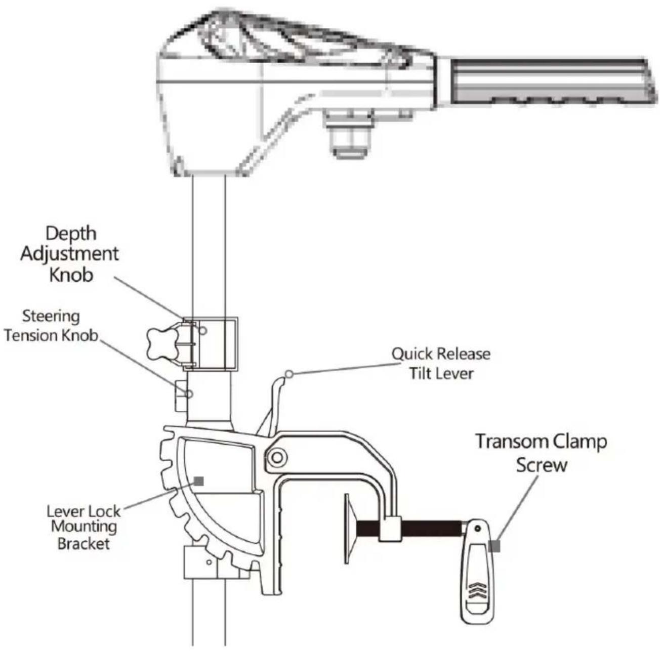
2. Adjusting the Depth of the Motor
When setting the depth be sure the top of the motor is submerged at least avoid churning or agitation of surface water. The propeller must be completely submerged.
a. Firmly grasp the composite Shaft and hold it steady.
b. Loosen the Steering Tension Knob and the Adjustable Depth Collar until the Shaft slides freely.
c. Raise or lower the motor to the desired depth.
d. Tighten Adjustable Depth Collar to secure the motor in place.
NOTICE: Be sure the top of the motor is submerged at least 12" below the of the water to avoid churning or agitation of surface water.
WARNING
The motor head will create a pinch point if the Steering Tension Knob is low and the motor head slides to the top of the Adjustable Depth Collar. Grasp Shaft and prevent it from sliding all the way down to prevent the pinch point the motor away from the area that may come in contact with another area motor to prevent injury.
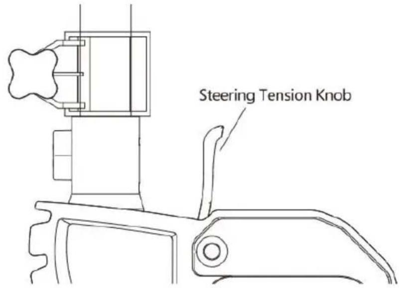
3. Adjusting the Steering
Adjust the Steering Tension Knob to provide enough tension to allow the motor turn freely, yet remain in any position without being held or tighten the knob. Place the motor in a preset position to leave your hands free for fishing.
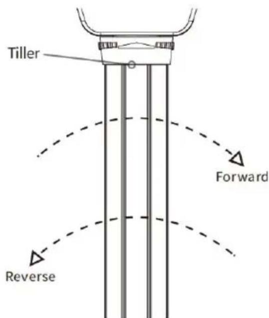
4. Controlling Speed & Direction with the Tiller
These motors are equipped with a handle, which offers variable forward and reverse speeds. The speed control may be operated in either direction, forward reverse. Turn the tiller handle counterclockwise from (OFF) to increase reverse speed and clockwise from (OFF) to increase forward speed. Thrust decreases you approach (OFF) from either direction.
WARNING
When the motor is not in use, always turn the Tiller handle to "OFF". If there is set or accidentally engaged or bumped and is not positioned to "OFF" the will turn on unexpectedly. The prop may also turn on unexpectedly if the corner board or 5 position switch fails. Prevent injury from a turning propeller and a know how to quickly disengage the power or correct the Tiller to turn the pi
WARNING
The Riptide Transom is not intended to be a primary propulsion motor. Heav of the motor can cause elevated motor temperatures, which can be increased an excessively hot operating environment. Use care when handling the control head to avoid burns or injuries from excessive heat. In the event that the n speed control would break, always be prepared to take manual control of the
WARNING
Be alert for unexpected boat movement when operating the Riptide Transom. boat may encounter sharp turns and jolts if the steering is changed sharply broad changes in speed are made while operating. Maintain balance and obso safe motor operation.
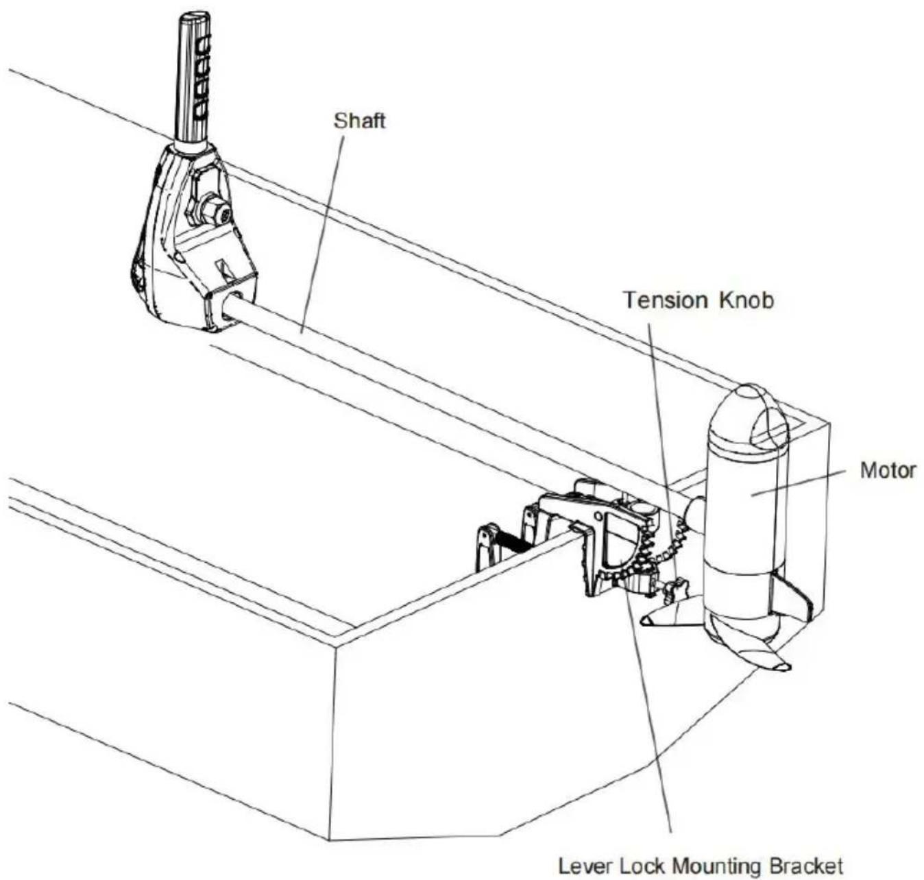
5. Adjusting the Bracket
You can lock your motor in a vertical position, angle it for shallow water or completely out of the water
a. Firmly grasp the control head or composite shaft.
b. Press the Quick Release Tilt Lever toward the shaft and hold to release detent lock or T-bar to adjust the position of the mounting bracket.
c.Tilt to any of the positions on the Lever Lock Mounting Bracket.
d. Release the Quick Release Tilt Lever.
WARNING
When adjusting the Lever Lock Mounting Bracket by engaging the Quick Rele Tilt Lever, watch for pinch points on the Lever Lock Mounting Bracket and b the Shaft and mounting bracket. Grasp the motor away from the area that n come in contact with another area of the motor to prevent injury.
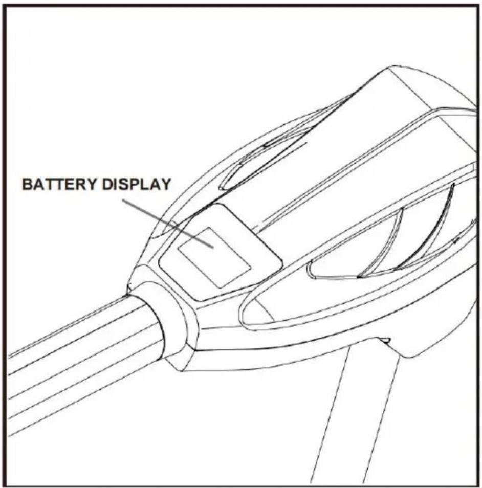
6. LED LIGHTS SHOW THE BATTERY CAPACITY
The LED light provides an accurate display of the remaining charge in battery.
- 2-3 lights will have deep warning, and then i will have around 10mins to back(Refer to battery 24V 60AH)
SERVICE & MAINTENANCE
1.PROPELLER REPLACEMENT
1.1 TOOLS AND RESOURCES REQUIRED
- 1/2" Open End Wrench • Flat Blade Screwdriver
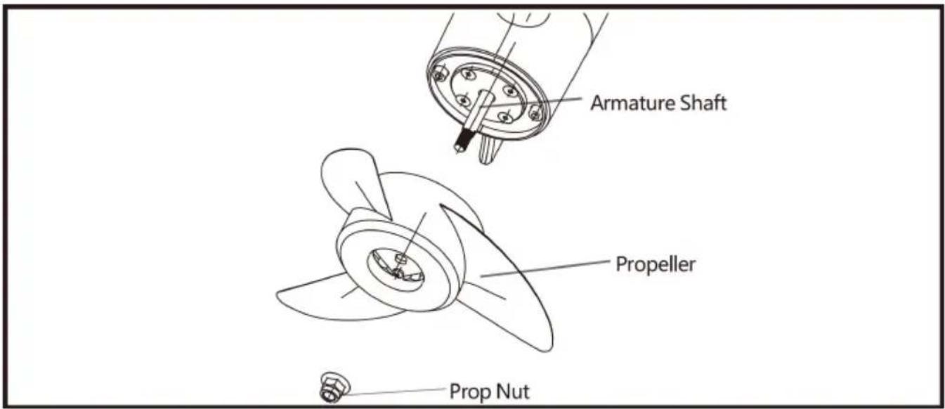
1.2 INSTALLATION
Step 1.
a. Disconnect the motor from all sources of power prior to changing the proj
b. Hold the propeller and loosen the Prop Nut with a pliers or a wrench.
c. Remove the Prop Nut and Prop Washer.
CAUTION
Disconnect the motor from the battery before beginning any prop work or maintenance.
Step 2
d. Turn the old prop to horizontal and pull it straight off.
CAUTION
If the prop does not readily slide off, take care to not bend the Armature S while removing the prop by pulling the prop evenly off the Armature Shaft.
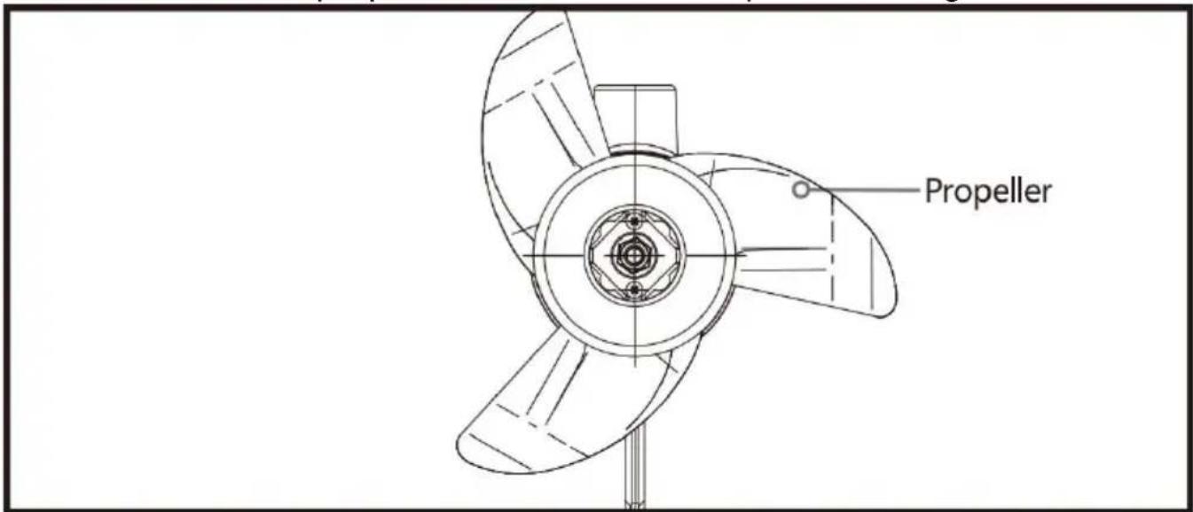
Step 3
e. Put on the new Propeller.
f. Install the Prop Nut.
g. Tighten the Prop Nut 1/4 turn past snug at 25-35 inch-lbs.
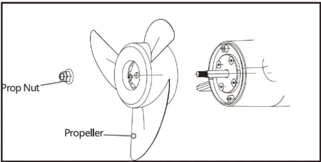
CAUTION
Do not over tighten as this can damage the prop.
GENERAL MAINTENANCE
-
After every use, the entire motor should be rinsed with freshwater, then windown with a cloth dampened with an aqueous based silicone spray. Do not water into the ventilation openings in the head of the motor.
-
The composite shaft requires periodic cleaning and lubrication for proper retraction and deployment. A coating of an aqueous based silicone spray will improve operation.
-
The propeller must be inspected and cleaned of weeds and fishing line after every use. Fishing line and weeds can get behind the prop, damage the sea allow water to enter the motor.
-
Verify the prop nut is secure each time the motor is used.
-
To prevent accidental damage during transportation or storage, disconnect the battery whenever the motor is off of the water. For prolonged storage, lightly all metal parts with an aqueous based silicone spray.
-
For maximum battery life, recharge the battery(s) as soon as possible after
For maximum motor performance, restore battery to full charge prior to use.
- Keep battery terminals clean with fine sandpaper or emery cloth (flooded le acid only).
- The propeller is designed to provide optimum operation with very high efficiency. To maintain this top performance, the leading edge of the blades is be kept smooth. If they are rough or nicked from use, restore to smooth by with fine sandpaper.
TROUBLESHOOTING
-
Motor fails to run or lacks power:
-
Check battery connections for proper polarity.
- Make sure terminals are clean and corrosion free. Use fine sandpaper or cloth to clean terminals.
-
Check battery water level. Add water if needed.
-
Motor loses power after a short running time:
-
Check battery charge. If low, restore to full charge.
-
Motor is difficult to steer:
-
Loosen the steering tension knob on the bracket
-
Lubricate the composite shaft.
-
You experience prop vibration during normal operation:
-
Remove and rotate the prop 180^ . See removal instructions in the Propeller Replacement section.
NOTICE: For all other malfunctions, visit an Authorized Service Center. You can search for an Authorized Service Center in your area by visiting our Authorization Service page
COMPLIANCE STATEMENTS
ENVIRONMENTAL COMPLIANCE STATEMENT
It is the intention of VEVOR to be a responsible corporate citizen, operating compliance with known and applicable environmental regulations, and a good neighbor in the communities where we make or sell our products.
INDUSTRY CANADA COMPLIANCE
This product meets the applicable Industry Canada technical specifications.
Operation is subject to the following two conditions: (1) this device may not interfere, and (2) this device must accept any interference, including interference that may cause undesired operation of the device.
Changes or modifications not expressly approved by Johnson Outdoors Marine Electronics, Inc. could void the user's authority to operate this equipment.
ENVIRONMENTAL RATINGS
Ambient operating temperature range: -10C to 50C
Ambient operating humidity range: 5% to 95%
Maximum operating altitude: 10,000 feet
PARTS DIAGRAM & PARTS LIST
This page provides VEVOR® WEEE compliance disassembly instructions. For more information about where you should dispose of your waste equipment for recycling and recovery and/or your European Union member state requirements please contact your dealer or distributor from which your product was purchased. Tools required, but not limited to: flat head screw driver, Phillips screw driver, socket set, pliers, wire cutters.
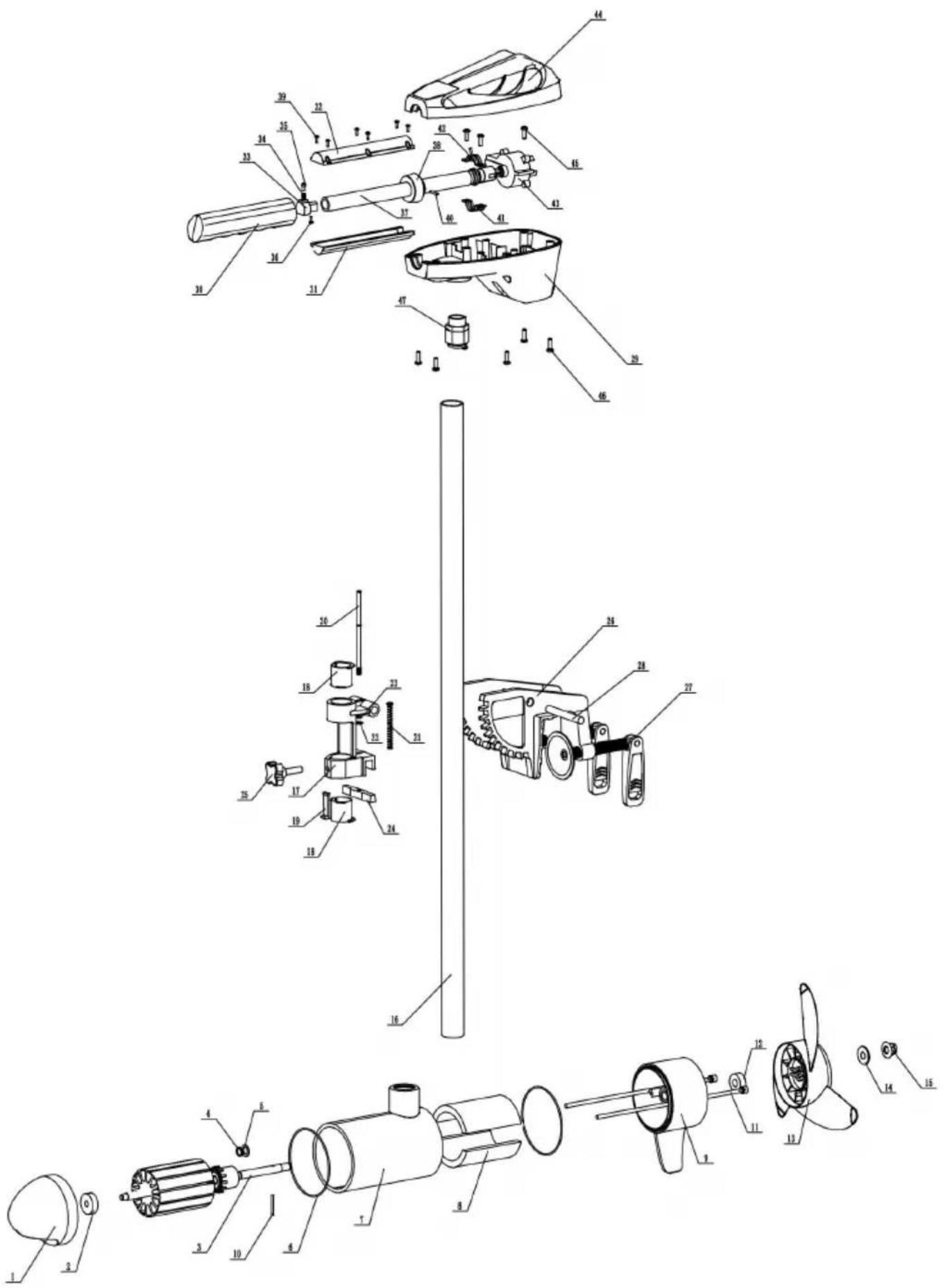
| item | description | specification | quantity |
| 1 | Motor front cover | 1 | |
| 2 | Deep hook ball bearings | 638-2RS (8*28*9) | 1 |
| 3 | Motor shaft | 1 | |
| 4 | E-Clip | D9 | 1 |
| 5 | Igus Gasket | 10*1 | 1 |
| 6 | O-ring seals | 90.2* 1.9 | 2 |
| 7 | Motor Housing | 1 | |
| 8 | Magnets | Npole Spole | 1set |
| 9 | Motor Back Cover | 1 | |
| 10 | Cylindrical pins | D3*20 | 1 |
| 11 | Hexagon socket cheese head screw | M6*215 | 2 |
| 12 | Skeleton Double Lip Oil Seal | 10*25*7 | 1 |
| 13 | Propeller | 1 | |
| 14 | Anti-corrosion zinc block | 1 | |
| 15 | Metal hexagonal flange nuts | M8 | 1 |
| 16 | Intermediate support tube | 1 | |
| 17 | Suspension snap support fittings | 1 | |
| 18 | Cylindrical pins | D10*75 | 1 |
| 19 | M6 fastener assembly | 1 | |
| 20 | Pins | 1 | |
| 21 | Compression springs | 304 | 1 |
| 22 | Flat Washers | D5*D10*1 | 1 |
| 23 | E-Clip | D3.5 | 1 |
| 24 | S cam | 1 | |
| 25 | M8 Tightening Handle | M8 | 1 |
| 26 | Switches | 1 | |
| 27 | Segmented foot assembly, knuckle | 2 | |
| 28 | Suspension Clip | 1 | |
| 29 | Upper Rudder Lower Housing | 1 | |
| 30 | Handle Rubber Sleeve | 1 | |
| 31 | Handle telescopic sleeve lower housi | 1 | |
| 32 | Handle Retractor Upper Housing | 1 | |
| 33 | Spring base | 1 | |
| 34 | Compression spring | D5*D0.5*10 | 1 |
| 35 | Handle Retractable Pins | 1 | |
| 36 | Cross recessed self-tapping screws | 2.6*12 | 1 |
| 37 | Handle | 1 | |
| 38 | Handle Retaining Sleeve | 1 | |
| 39 | Cross recessed tapping screws | 2.9*4.5 | 6 |
| 40 | Cylindrical pins | D2.5*25 | 1 |
| 41 | Lower Clip | 1 | |
| 42 | Upper Clip | 1 | |
| 43 | Switch Unit | 1 | |
| 44 | Upper rudder upper housing | 1 | |
| 45 | Cross recessed self-tapping screws | 3.9*9.5 | 1 |
| 46 | Cross recessed self-tapping screws | 4.2*16 | 6 |
| 47 | 13.5PG waterproof connector | 1 |
Manufacturer: Shanghaiuxinmuyeyouxianggsi
Address: Shuangchenglu 803nong11hao1602A-1609shi, baoshanqu, shanghai 200000 CN.
Imported to AUS: SIHAO PTY LTD. 1 ROKEVA STREETEASTWOOD NSW 2122 Australia
Imported to USA: Sanven Technology Ltd. Suite 250, 9166 Anaheim Place, Rancho Cucamonga, CA 91730
| EC | REP |
E-CrossStu GmbH
Mainzer Landstr.69, 60329 Frankfurt am Main
| UK | REP |
YH CONSULTING LIMITED.
C/O YH Consulting Limited Office 147, Centurion House, London Road, Staines-upon-Thames, Surrey TW18 4AX
VEVOR®
TOUGH TOOLS, HALF PRICE
Technical Support and E-Warranty Certificate
www.vevor.com/support
VEVOR®
TOUGH TOOLS, HALF PRICE
Assistance technique et certificat de garantie electronique www.vevor.com/support
A/S YH Consulting Limited Bureau 147, Centurion
Maison, London Road, Staines-upon-Thames, Surrey, TW18 4AX
VEVOR
TOUGH TOOLS, HALF PRICE
Assistance technique et certificate de garantie
YH CONSULTING LIMITED.
C/O YH Consulting Limited Office 147, Centurion Haus, London Road, Staines-upon-Thames, Surrey, TW18 4AX
VEVOR
TOUGH TOOLS, HALF PRICE
www.vevor.com/support
VEVOR
TOUGH TOOLS, HALF PRICE
www.vevor.com/support Questa
Importato in AUS: SIHAO PTY LTD. 1 ROKEVA STREETEASTWOOD
Nuovo Galles del Sud 2122 Australia
C/O YH Consulting Limited Ufficio 147, Centurion Casa, London Road, Staines-upon-Thames, Surrey,
Modello TW18 4AX
VEVOR
TOUGH TOOLS, HALF PRICE
Casa, London Road, Staines-upon-Thames, Surrey,
TW18 4AX
VEVOR
TOUGH TOOLS, HALF PRICE
TABLEA DOBORU PRZEWODOW I WYMIAROW WYLACZNIKOW
C/O YH Consulting Limited Biuro 147, Centurion
Dom, London Road, Staines-upon-Thames, Surrey, TW18 4AX
VEVOR
TOUGH TOOLS, HALF PRICE
HULP NODIG? NEEM CONTACT MET ONS OP!
De as glijdt vrij.c.Breng
C/O YH Consulting Limited Kantoor 147, Centurion Huis, London Road, Staines-upon-Thames, Surrey, TW18 4AX
VEVOR
TOUGH TOOLS, HALF PRICE
Technische ondersteuning en e-garantiecertificaat www.vevor.com/support
VEVOR
TOUGH TOOLS, HALF PRICE
Referens United States Code of Federal Regulations: 33 CFR 183 - Boats and Associated Equipment ABYC E-11: AC and DC Electrical Systems on Boats.
VALJA RATT BATTERIER
Motornkommenattfungera med alla blysyra, djupgaende marina 12 volts
YH CONSULTING LIMITED.
C/O YH Consulting Limited Office 147, Centurion House, London Road, Staines-upon-Thames, Surrey, TW18 4AX
VEVOR®
TOUGH TOOLS, HALF PRICE
www.vevor.com/support