K1E01027 - Grooming set Vevor - Free user manual and instructions
Find the device manual for free K1E01027 Vevor in PDF.

| Product Type | Pet Grooming Bathtub |
| Brand | Vevor |
| Model | K1E01027 |
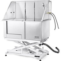
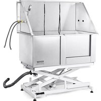
| Dimensions (L x W x H) | 1270 x 700 x 1295 mm (minimum height) |
| Adjustable Height | 450-500 mm (lifting stroke: 560 mm) |
| Maximum Load Capacity | 150 kg (330 lbs) |
| Power Supply | AC 120 V (U model) or AC 220-240 V (E, A models) |
| Rated Power | 50 W (U) or 90 W (E, A) |
| Plug Type | American (U), European (E), Australian (A) |
| Main Material | Plastic and metal |
| Electric Lifting Function | Yes, with + and - buttons to adjust height |
| Overload Protection | Yes, overcurrent and overheat protection |
| Door | Yes, installed on the bathtub |
| Water Faucets | Hot and cold water (H and C marks) |
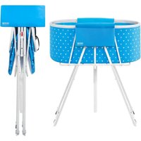
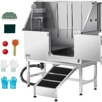
| Included Accessories | Shower head, inlet hose, drain hose, storage basket, shower holder, comb, sling, toy, gloves, wrench, adapter |
| Intended Use | Bathing pets (cats, medium-sized dogs) |
| Maintenance & Cleaning | Clean with a soft cloth and mild detergent after each use; regularly clean the strainer and transparent cover |
| Safety Instructions | Do not use for humans; keep children away; do not exceed maximum load; use on a flat, non-slip surface |
| Compliance | FCC Part 15; European WEEE Directive 2012/19/EC |
Frequently Asked Questions - K1E01027 Vevor
User questions about K1E01027 Vevor
0 question about this device. Answer the ones you know or ask your own.
Ask a new question about this device
Download the instructions for your Grooming set in PDF format for free! Find your manual K1E01027 - Vevor and take your electronic device back in hand. On this page are published all the documents necessary for the use of your device. K1E01027 by Vevor.
USER MANUAL K1E01027 Vevor
Affordable. Reliable. Home Improvement.
DOG GROOMING TUB
MODEL: K1E01027-U/K1E01027-E/K1E01027-A
K1E01028-U/K1E01028-E/K1E01028-A
MODEL: K1E01027-U/K1E01027-E/K1E01027-A K1E01028-U/K1E01028-E/K1E01028-A

natural_image
Technical line drawing of a mechanical device with no visible text or symbols
natural_image
Technical line drawing of a mechanical device with no visible text or symbolsThis is the original instruction, please read all manual instructions carefully before operating. VEVOR reserves a clear interpretation of o user manual. The appearance of the product shall be subject to the product you received. Please forgive us that we won't inform you ag there are any technology or software updates on our product.

WARNING: Read and understand this entire manual before operating or servicing this product. Failure to follow these warnings and instructions can cause personal injury or damage to valuable property.
- Avoid children using grooming tub. And this product is not a toy. allow children to play.
-
Keep away from sharp points, blades and other items.
-
Please wipe the cylinder dry with a cloth after use to extend the life.
-
Assembly precautions
-
Assemble only according to these instructions. Improper assembly c create hazards.
- Wear ANSI-approved safety goggles and heavy-duty work gloves du assembly.
- Keep assembly area clean and well-lit.
- Keep bystanders out of the area during assembly.
- Do not assemble when tired or when under the influence of alcohol drugs or medication.
- Product capabilities apply to properly and completely assembled pro only.
- For additional information regarding the parts listed in the following pages, please refer to the Assembly Diagram of this manual. Unwrap separate all parts in a clean work area. Please keep small spare pa of children's reach.
| FC | This device complies with Part 15 of the FCC Rules. is subject to the following two conditions:(1)This device not cause harmful interference, and (2)this device must any interference received, including interference that m cause undesired operation. |
| This product is subject to the provision of European D 2012/19/EC. The symbol showing a wheelie bin cros through indicates that the product requires separate re collection in the European Union. This applies to the and all accessories marked with this symbol. Products as such may not be discarded with normal domestic w must be taken to a collection point for recycling electr electronic devices |
SAVE THESE INSTRUCTIONS
natural_image
Simple line drawing of a standing dog (no text or symbols)Warning!Products are only used for pet bathing.
PREPARATIONS BEFORE INSTALLATION
- Recommended Tools:
Phillips screwdriver, M4 wrench, Spirit level,
- Necessary safety equipment:
Gloves, goggles.
Caution: Before installing the product, wear gloves and goggles to av possible physical damage during installation.
INSTRUCTIONS
Thank you very much for choosing this pet bathtub. Please read all instructions before using it. The information will help you achieve the possible results.
Parts List
 |  |  |  |
| 1 pc | 1 pc | 1 pc | 1 pc |
| 1: Bottom bracket1-1: Control Box | 2: Tub | 3: Right side panel | 4: Left side panel |
| 1 pc | 2 pcs | 1 pc | 1 pc |
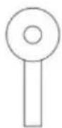
| 5: Door(Already Installedto the tub) | 6-1: Small PlastiFloor Grate6-2: Big PlasticFloor Grate | 7: Back panel | 8: Faucetswitch |
 |  |  | 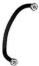 |
| 1 pc | 1 pc | 1 pc | 2 pcs(600mm) |
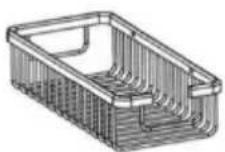
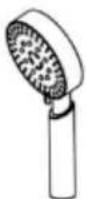
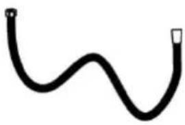
| 9: Storagebasket | 10: Shower head | 11: Showerhose | 12: Inlet pipe |
 | 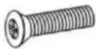 |  | 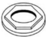 |
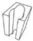
| 1 pc | 4 pcs(M4*16mm) | 4 pcs | 2 pcs |
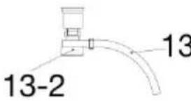
| 13: Strainer13-1: Drain Pipe13-2:TransparentCover | 14: Screw | 15: Hex flangenut | 16: Nut |
 |  |  |  |
| 1 pc | 1 pc | 2 pcs | 2 pcs |
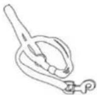
| 17: Shower bracket | 18: Comb | 19: Sling | 20: Play ball |
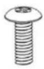 | 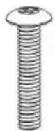 |  |  |
| 20 pcs (M6*16mm) | 6 pcs (M8*40mm) | 1 pc | 2 pcs |
| 21: Screw | 22: Screw | 23: Plastic Gloves | 24: Washer |
 |  | ||
| 1 pc | 2 pcs | ||
| 25: Crossbar | 26: Nut | ||
 |  |  |  |
| 1 pc | 1 set | 1 pc | 1 pair |
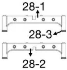
27: Sealing tape | 28: Base 28-1: Down Bas 28-2: Up Base 28-3: Anti-slip Mat | 29: Wrench | 30: Nylon Gloves |
| 1 pc | 4 pcs(M8*20mm) | 1 pc | 2 pcs |
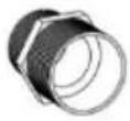
| 31: Wiper | 32: Screw | 33: Scouring pad | 38: Adapter(G1/2 to NPT9/16) |
Installation Steps
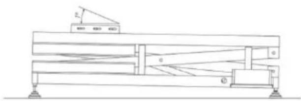
natural_image
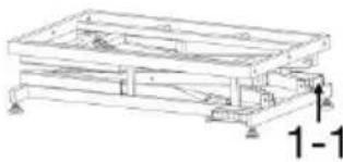
Technical line drawing of a mechanical support structure with no visible text or symbols①Flip the bottom bracket, adjust the height of the feet to make height of water outlet side is 1-2 degrees lower than the other spirit level to show)
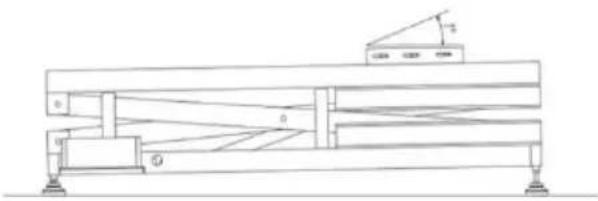
natural_image
Technical line drawing of a mechanical assembly with no visible text or symbols
natural_image
Technical line drawing of a mechanical structure with beams and supports, no text or symbols present②Plug in and then press the “+” button of the pe and raise the stand to a height of 450-500mm
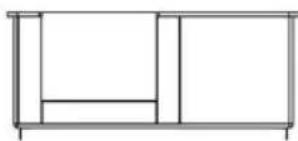
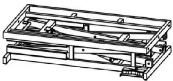
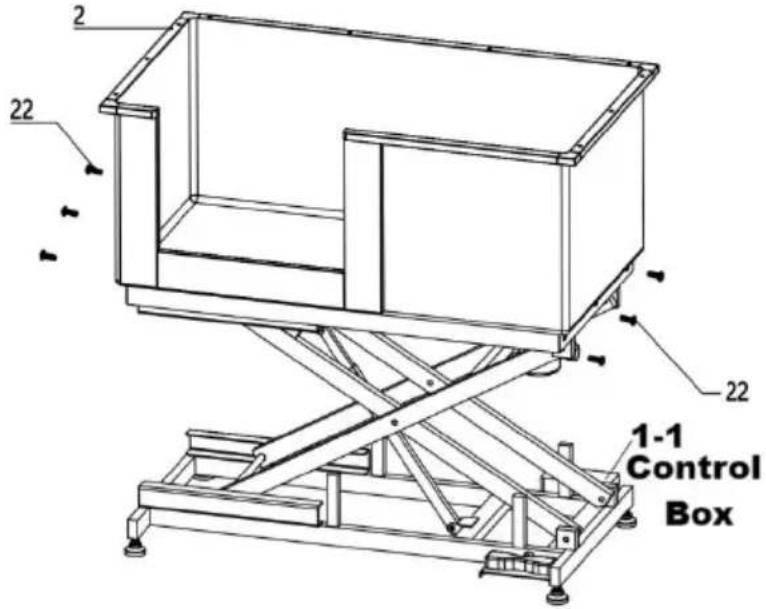 | 3 Flip the bottom brack and use screw to fix the bottom bracket and tub |
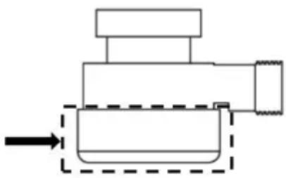
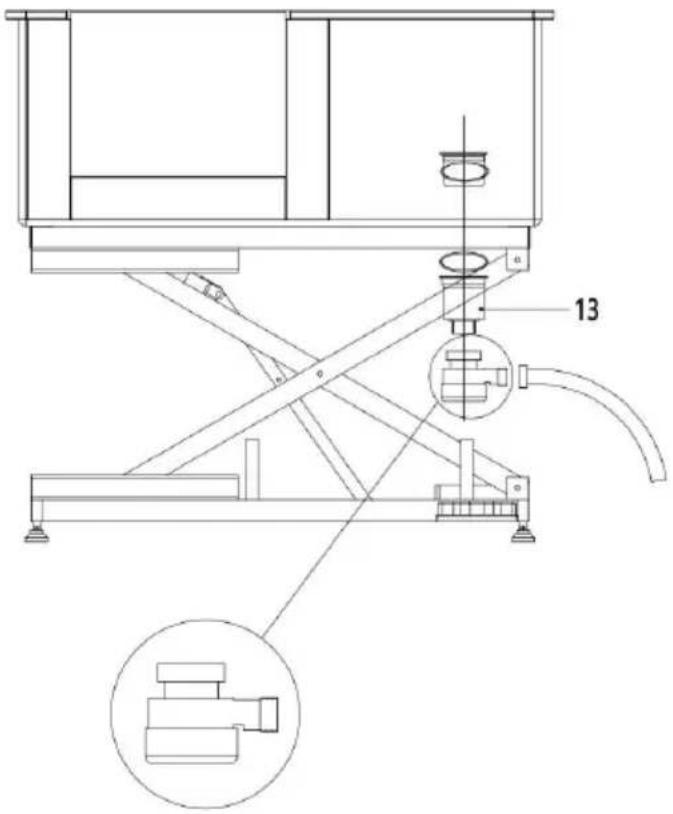 | 4 Install the strainer,Make sure the drainpipe is facing outwards so they are not compressed during the lowering of bottom bracket.Caution: Ensure that the depth of adjustable feet is not less than 12mm, and to make the four adjustable feet screw in the same depth. Please tighten the spare nut during the installation and adjust it later. And check whether the transparent cover of drain is tightened. |
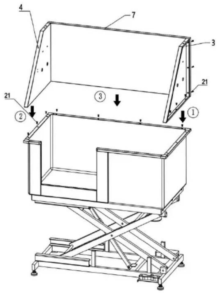
⑤ Use screw to fix the and right side board, the use screw to fix the back panel, last to use screw fix side board and back board
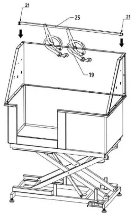
⑥ Use screw to fix the crossbar to the left and side panel, then install the sling
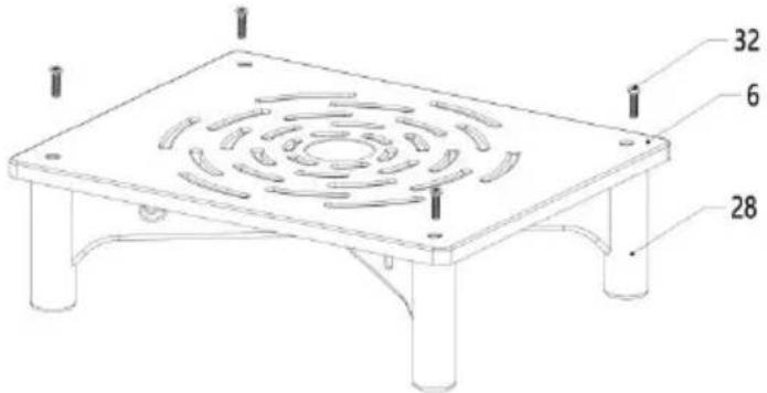 | 7 Install the handle to th water filter plate |
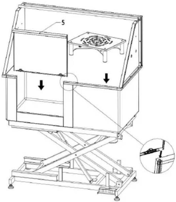 | 8 Install door and water filter plate |
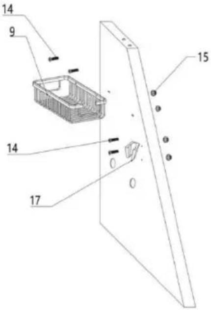 | 9 Use screw and hex flange nut to install the storage basket and show bracket to the right side panel |

38
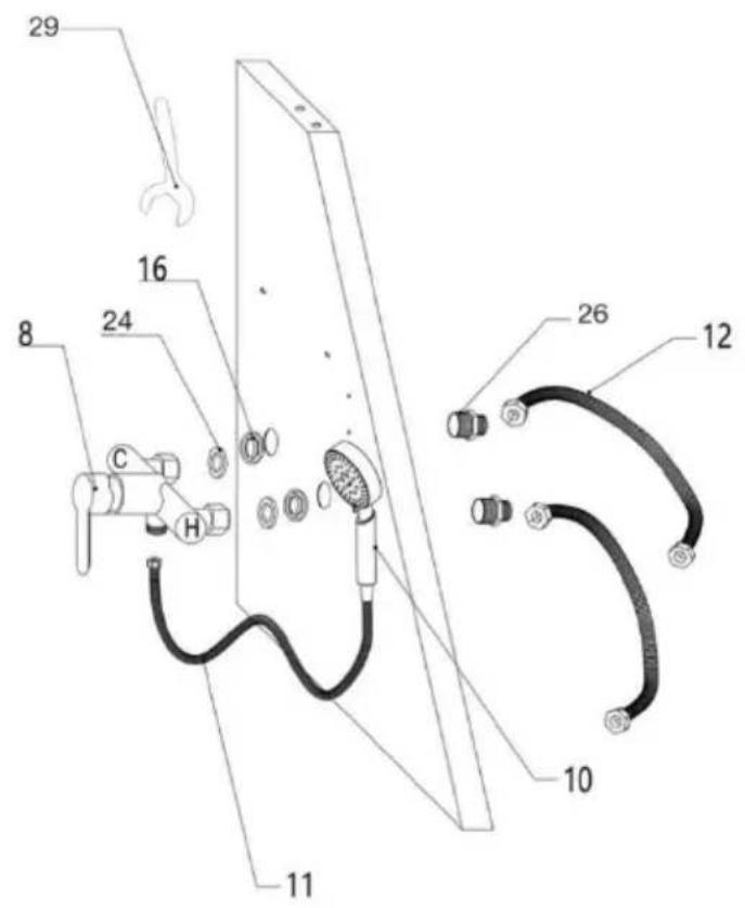
⑩ Install hot and cold shower switch and water inlet.
Caution: Before you do this, make sure that yo water source is on the or right side of the bathtub, and select the direction of installation the tap switch.
Step1: Pass straight all-copper connector through side panel (1/2" end facing outside), screw nut into the other end of the connect and use wrench screw down.
Step2: Align the faucet switch with the connector, then tighten nuts on the switch, and note that the sealing ring inside the n
Step3: Connect the hose at the water inlet end and the shower hose at the faucet outlet. Also, when tightening the nut, pay attention to the sealing ring inside the nut is intact.
Step4: The other end of the hose is connected to the water source, pay attention to the hot and cold water mark on the faucet switch, represents hot water, and connect the hose on this side to the source, while the other side is connected to the cold, also pay to whether the seal ring inside the hose end nut is intact.
Caution: The inlet hose is only 600mm long, if you want to le please purchase it separately (Caliber:20mm)
Caution: Optional use of sealing tape when installing the nut. It the installation more sealed and help prevent water leakage at
Caution: Please determine whether to install adapter according to actual water pipe specifications.
Left Door

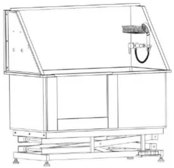
natural_image
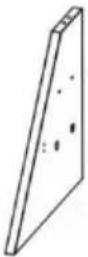
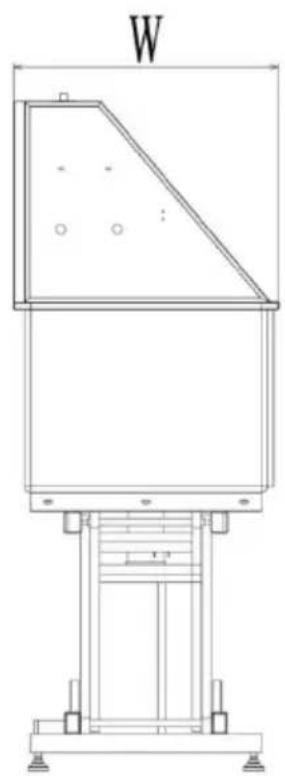
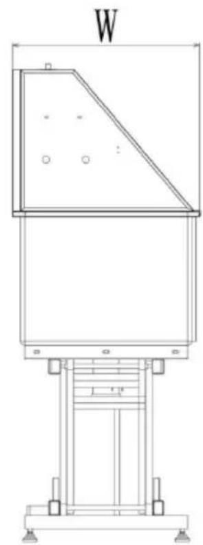
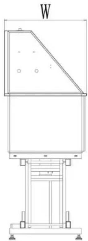
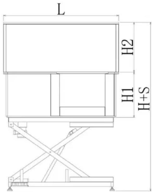
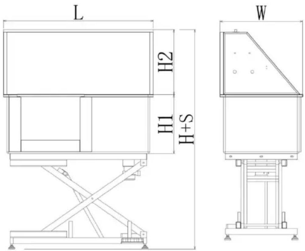
Technical line drawing of a mechanical device with a labeled dimension W (no text or symbols beyond the label)Right Door
natural_image
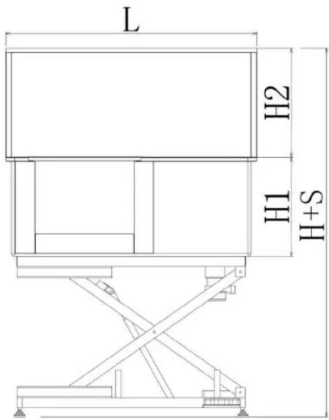
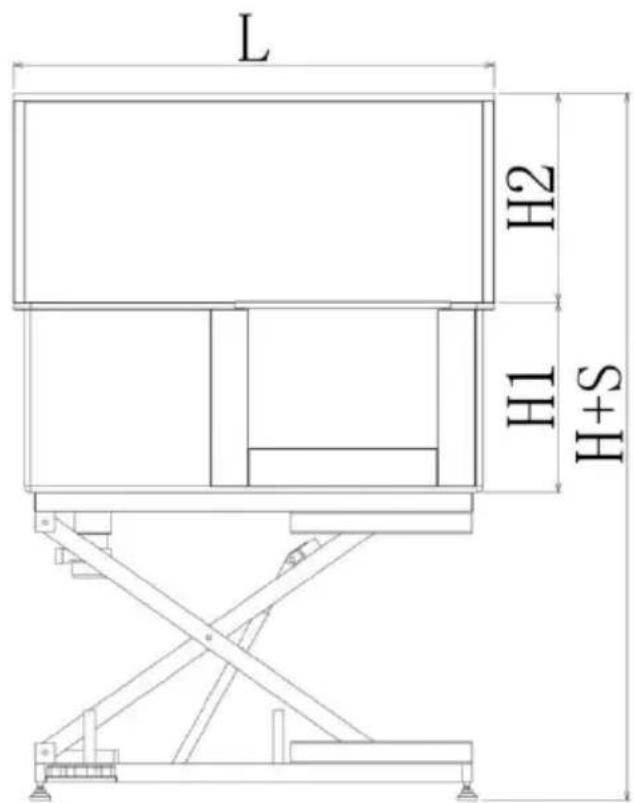
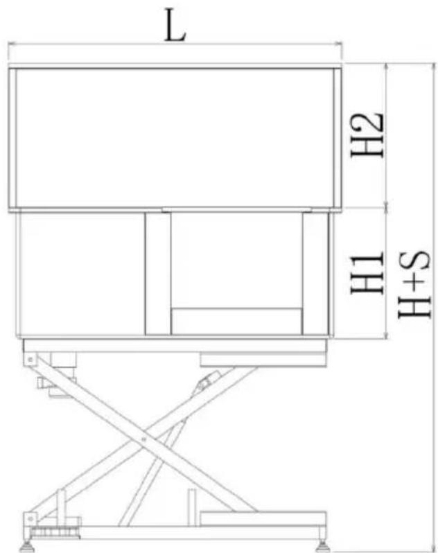
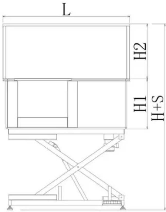
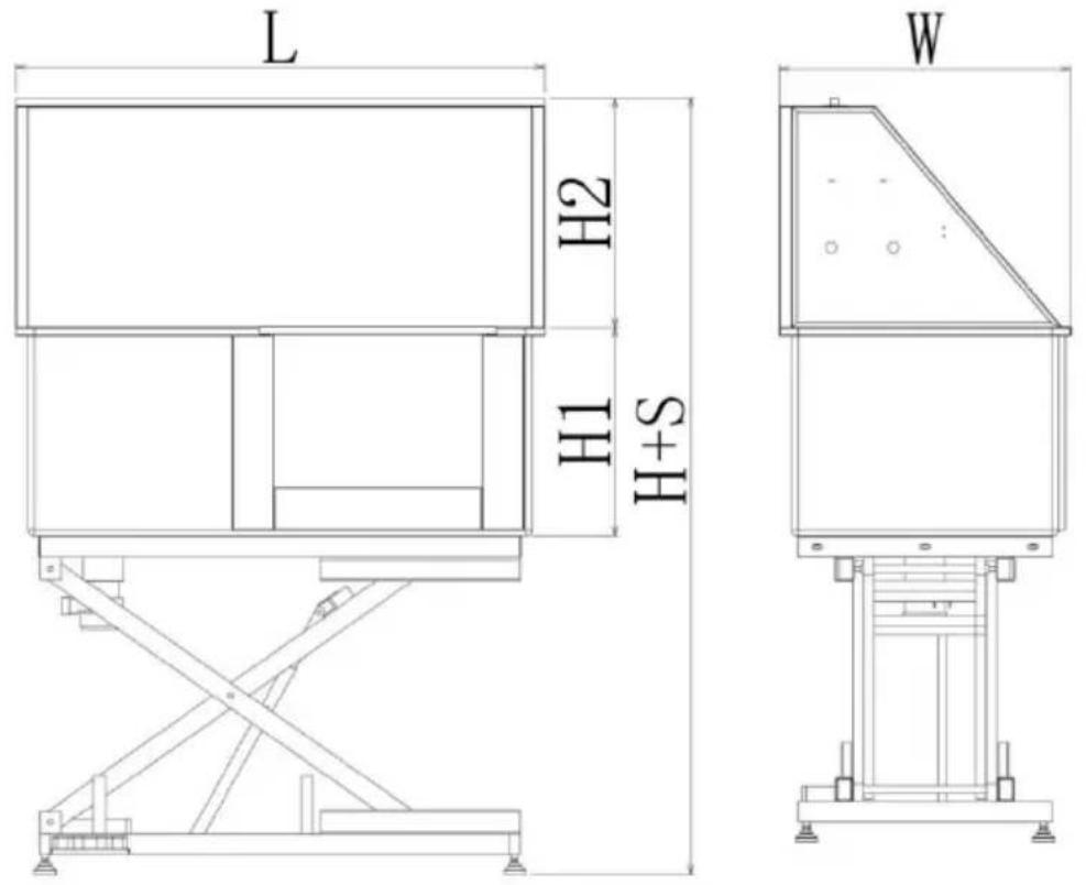
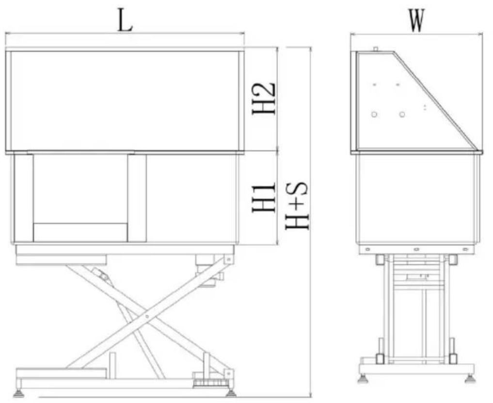
Technical line drawing of a mechanical device with labeled dimension W (no text or symbols beyond label)| Model# | L(mm) | H(mm) | S(mm) | H1(mm) | H2(mm) | W(mm) | N.W.(kg) |
| K1E01027-U | 1270 | 1295 | 565 | 500 | 530 | 700 | 79.7 |
| K1E01028-U | 1270 | 1295 | 565 | 500 | 530 | 700 | 79.7 |
| K1E01027-E | 1270 | 1295 | 565 | 500 | 530 | 700 | 79.7 |
| K1E01028-E | 1270 | 1295 | 565 | 500 | 530 | 700 | 79.7 |
| K1E01027-A | 1270 | 1295 | 565 | 500 | 530 | 700 | 79.7 |
| K1E01028-A | 1270 | 1295 | 565 | 500 | 530 | 700 | 79.7 |
| Model | K1E01027-UK1E01028-U | K1E01027-EK1E01028-E | K1E01027-AK1E01028-A |
| Dimension: | L1270xW700xH1295(min) | ||
| Travel | 560mm | ||
| LoadingCapacity: | 150kg/330lb | ||
| Plug standard | American plug | europlug | Australian plug |
| Overloadindication | Yes | Yes | Yes |
| Power: | 50W | 90W | 90W |
| Voltage: | AC120V | AC220-240V | AC220-240V |
OVERLOAD INDICATION
The electric push rod is equipped with over-current and over-heat protection. When the current is too large or the temperature is too high control box will start the protection measures and stop working. After
system takes a rest, the control box will automatically return to normal. It is recommended to work for 2 minutes. Take a rest for 18 min which can prevent the system from entering the protection mode affect the normal work.
FOOT BUTTON FUNCTIONS
Button Functions
- "+" Button: Pressing "+" button will rise the height.
- "—" Button: Pressing "—" will reduce the height.
OPERATION
- Make sure the water pipe connection is complete and the water is normally. (Connect the hot and cold water pipes according to the hot cold water signs of the faucet switch)

"C": Cold water; "H": Hot water
- Lower the bathtub to the lowest height, open the door, and let the walk into the bathtub by itself or hold the pet inside the tub by you close the door.
- Start to bath.
- After the bath, let the water out of the tub and take the animal oil
- Clean the tub with a cloth.
MAINTENANCE
- In between use, the tub should be cleaned with a soft cloth or sp
using a mild cleaning agent.
- Pay attention to regularly clean the hair of the drain to avoid clogg
- Please clean the transparent cover of the drain regularly, After disassembly like a nut, it can be easily cleaned, and be careful not the seal ring when installing it back.
natural_image
Pure mechanical diagram showing a piston-cylinder assembly with no text or symbolsCARE INSTRUCTIONS
Don't put the bathtub on an uneven surface.
Don't drop or mistreat the bathtub.
Don't overload the scale. This will permanently damage it!
If the machine cannot be lifted normally, please disconnect the power supply and check whether the wiring port is loose.
The faucet is leaking, please check whether the waterproof rubber plu installed, if it is damaged, it needs to be replaced in time.
Safety Information

Warning
General Safety Instructions
- Improper installation and/or operation may result in property damage injury to yourself or your pet. Follow the instructions carefully and cor customer service or a local contractor if any point is confusing, too for you to do on your own, or requires special modification for your Keep these instructions for future reference. Provide them to anyone will use this device and provide them with this device if it is ever g
sold to a third party.
- ONLY use this bathtub for its intended purpose, bathing medium-size pets such as cats and dogs.
- DO NOT use it with pets that exceed this product's weight capacity whose predisposition becomes violent upon contact with water, or who physiological features preclude safe regular bathing (e.g., chinchilla rat).
- NEVER use this bathtub for humans, especially children, or allow the play on or with it.
- DO NOT run or allow others to run in the area around this bathtub, allow children or pets to stay under the tub. Restrict access to the necessary.
- Ensure all components and fasteners are intact and securely tightened before use. Do not operate this bathtub if any part is damaged or signs of malfunction. Repair or replace problematic components before further use. NEVER replace any parts with nonidentical ones.
- Consult a veterinarian before use if your pet may have an illness or condition such as skin allergies that might be worsened by bathing. Only in compliance with the veterinarian's recommendations (e.g., using specially medicated shampoos).
- Be mindful of your pet's mood while using this bathtub. If unwillingness unavoidable, take precautions to prevent the pet from harming you, themselves, or others during bathing.
Provide a reward afterward.
- NEVER load this bathtub with more than 286 pounds (130 kg).
Particularly for larger animals, be careful to prevent them from jumping moving in such a way that causes violent impacts as this might exceed capacity.
- DO NOT leave this bathtub unattended during use.
Electrical Safety Instructions
- Ensure all electrical outlets and exposed electrical connections around are at least 10 feet (3 m) away from this bathtub or fully protected possible splashing during bathing. DO NOT use any chargers or exter cords closer than this distance without
similar protection.
- Electrical devices such as electrical transformers, televisions, lights, an telephones should be at least 6'7" (2 m) away from this bathtub at . In particular, never bring a chargingcell phone near the bathtub and allow any electrical device to be placed or used in such a way that fall into the water under any circumstance.
- For extra safety, install this bathtub at least 6'7" (2 m) away from conductive metal surfaces to reduce the risk of electric shock from splashing water. Any metal surface closer this should be permanently bonded to a dedicated terminal box with a solid copper conductor at gauge (3.3 m) thick.
Water Safety Instructions
- ONLY install this bathtub on firm, level, and nonslip surfaces that do its weight while filled with your pet and water. The surfaces must be impervious to damage from moisture and the surrounding area must be able to handle the expected humidity created by the water.
- An adequate drainage system should be provided to safely deal with overflow and to permit easy emptying of this bathtub.
- Make sure your water supply for this bathtub is turned off during installation.
- NEVER allow the water level to rise above the level of your pet's during use.
- DO NOT set up or leave this bathtub in temperatures below 32^ . Do not turn on the shower if there is any possibility water in its line frozen.
- DO NOT add chemicals other than standard mild soaps and pet shampoos to the bathingwater. After use, only apply nontoxic cleaning agent to the bathtub's internal surface and rinse it away completely. For sterilization, only use pet-safe and nontoxic disinfectants.
- DO NOT allow dirty and stagnant water to remain in this bathtub long period. Drain, clean, and dry the tub completely after each use.
Heat Safety Instructions
- Adequate ventilation should be provided to safely deal with the expected heat and humidity.
- The water temperature should be close to your pet's body temperat. Water that is either too cold or too hot will cause discomfort, may in your pet's skin, and may even cause injury or illness.Before use, lear about the appropriate water temperatures for bathing your pet.For best results, set your water heater's maximum temperature accordingly if possible.If adding preheated water, make sure it is within the tempera range appropriate for your pet before allowing your pet to enter.

VEVOR
Affordable. Reliable. Home Improvement.
BAIGNOIRE DE TOILETTAGE POUR CHIEN
MODÈLE : K1E01027 -U/ K1E01027 -E/ K1E01027 -A
K1E0102 8-U/ K1E0102 8-E/ K1E0102 8-A
MODÈLE : K1E01027 -U/ K1E01027 -E/ K1E01027 -A K1E0102 8-U/ K1E0102 8-E/ K1E0102 8-A

natural_image
Technical line drawing of a mechanical device with no visible text or symbols
natural_image
Technical line drawing of a mechanical device with no visible text or symbolsnatural_image
Simple line drawing of a standing dog (no text or symbols)natural_image
Technical line drawing of a structural beam with supports and a support structure (no text or symbols)natural_image
Technical line drawing of a mechanical assembly with no visible text or symbols
natural_image
Technical line drawing of a mechanical structure with beams and supports, no text or symbols presentDIMENSIONS AND PARAMETERS
Porte de gauche

Porte droite

| Modèle # | L (mm) | H (mm) | S (mm) | H1 (mm) | H2 (mm) | W (mm) | Poids net (kg) |
| K1E01 027-U | 1270 | 1295 | 565 | 500 | 530 | 700 | 79,7 |
| K1E01 028-U | 1270 | 1295 | 565 | 500 | 530 | 700 | 79,7 |
| K1E01 027-E | 1270 | 1295 | 565 | 500 | 530 | 700 | 79,7 |
| K1E01 028-E | 1270 | 1295 | 565 | 500 | 530 | 700 | 79,7 |
| K1E01 027-A | 1270 | 1295 | 565 | 500 | 530 | 700 | 79,7 |
| K1E01 028-A | 1270 | 1295 | 565 | 500 | 530 | 700 | 79,7 |
FOOT BUTTON FUNCTIONS
natural_image
Pure mechanical diagram showing a piston-cylinder assembly with no text or symbolsAffordable. Reliable. Home Improvement.
HUNDEPFLEGEWANNE
MODELL: K1E01027 -U/ K1E01027 -E/ K1E01027 -A
K1E0102 8-U/ K1E0102 8-E/ K1E0102 8-A
MODELL: K1E01027 -U/ K1E01027 -E/ K1E01027 -A K1E0102 8-U/K1E0102 8-E/ K1E0102 8-A

natural_image
Technical line drawing of a mechanical device with no visible text or symbols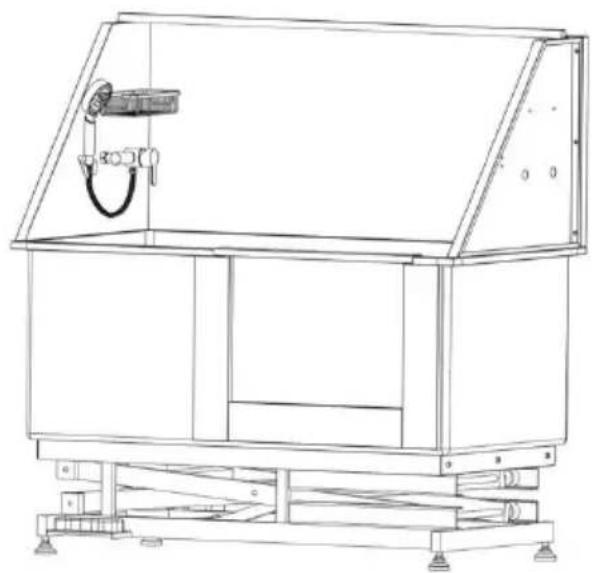
natural_image
Technical line drawing of a mechanical device with no visible text or symbolsnatural_image
Simple line drawing of a standing dog (no text or symbols)natural_image
Technical line drawing of a mechanical support structure with no visible text or symbols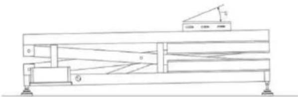
natural_image
Technical line drawing of a mechanical support structure with no visible text or symbolsDIMENSIONS AND PARAMETERS
Linke Tür

natural_image
Technical line drawing of a mechanical device with no visible text or symbolsRechte Tür
natural_image
Technical line drawing of a mechanical device with no visible text or symbols| Modell# | L(mm) | H(mm) | S(mm) | H1(mm) | H2(mm) | W(mm) | Nettogewicht(kg) |
| K1E01 027-U | 1270 | 1295 | 565 | 500 | 530 | 700 | 79,7 |
| K1E01 028-U | 1270 | 1295 | 565 | 500 | 530 | 700 | 79,7 |
| K1E01 027-E | 1270 | 1295 | 565 | 500 | 530 | 700 | 79,7 |
| K1E01 028-E | 1270 | 1295 | 565 | 500 | 530 | 700 | 79,7 |
| K1E01 027-A | 1270 | 1295 | 565 | 500 | 530 | 700 | 79,7 |
| K1E01 028-A | 1270 | 1295 | 565 | 500 | 530 | 700 | 79,7 |
FOOT BUTTON FUNCTIONS
Tastenfunktionen
natural_image
Pure mechanical diagram showing a piston-cylinder assembly with no text or symbolsCARE INSTRUCTIONS
Affordable. Reliable. Home Improvement.
VASCA PER LA TOELETTATURA DEI CANI
MODELLO: K1E01027 -U/ K1E01027 -E/ K1E01027 -A
K1E0102 8-U/ K1E0102 8-E/ K1E0102 8-A
VEVOR
Affordable. Reliable. Home Improvement.
DOG GROOMING TUB
MODELLO: K1E01027 -U/ K1E01027 -E/ K1E01027 -A K1E0102 8-U/K1E0102 8-E/ K1E0102 8-A
natural_image
Technical line drawing of a mechanical device with no visible text or symbols
natural_image
Technical line drawing of a mechanical device with no visible text or symbolsnatural_image
Simple line drawing of a standing dog (no text or symbols)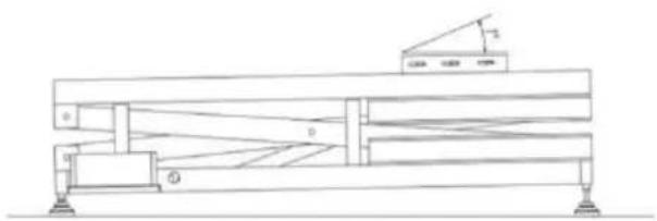
natural_image
Technical line drawing of a mechanical support structure with no visible text or symbolsnatural_image
Technical line drawing of a mechanical assembly with no visible text or symbols
natural_image
Technical line drawing of a mechanical structure with beams and supports, no text or symbols presentDIMENSIONS AND PARAMETERS
Porta sinistra

natural_image
Technical line drawing of a mechanical device with no visible text or symbolsPorta destra

natural_image
Technical line drawing of a mechanical device with no visible text or symbols| Modello# | L(mm) | H(mm) | S(mm) | H1(mm) | H2(mm) | O(mm) | Peso netto(kg) |
| K1E01 027-U | 1270 | 1295 | 565 | 500 | 530 | 700 | 79.7 |
| K1E01 028-U | 1270 | 1295 | 565 | 500 | 530 | 700 | 79.7 |
| K1E01 027-E | 1270 | 1295 | 565 | 500 | 530 | 700 | 79.7 |
| K1E01 028-E | 1270 | 1295 | 565 | 500 | 530 | 700 | 79.7 |
| K1E01 027-A | 1270 | 1295 | 565 | 500 | 530 | 700 | 79.7 |
| K1E01 028-A | 1270 | 1295 | 565 | 500 | 530 | 700 | 79.7 |
FOOT BUTTON FUNCTIONS
natural_image
Pure mechanical diagram showing a piston-cylinder assembly with no text or symbolsCARE INSTRUCTIONS
Affordable. Reliable. Home Improvement.
BAÑERA DE ASEO PARA PERROS
MODELO: K1E01027 -U/ K1E01027 -E/ K1E01027 -A
K1E0102 8-U/ K1E0102 8-E/ K1E0102 8-A
VEVOR
Affordable. Reliable. Home Improvement.
DOG GROOMING TUB
MODELO: K1E01027 -U/ K1E01027 -E/ K1E01027 -A K1E0102 8-U/K1E0102 8-E/ K1E0102 8-A

natural_image
Technical line drawing of a mechanical device with no visible text or symbols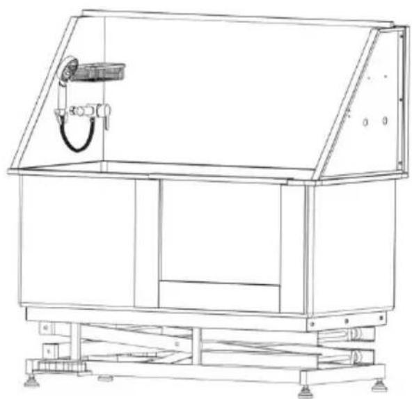
natural_image
Technical line drawing of a mechanical device with no visible text or symbolsnatural_image
Simple line drawing of a standing dog (no text or symbols)natural_image
Technical line drawing of a mechanical assembly with no visible text or symbols
natural_image
Technical line drawing of a mechanical structure with beams and supports, no text or symbols present④ Instale el filtro,
DIMENSIONS AND PARAMETERS
Puerta izquierda

Puerta derecha

| Modelo # | L (milímetros) | H (milímetros) | S (milímetros) | H1 (milímetros) | H2 (milímetros) | O (milímetros) | NO (kg) |
| K1E01 027-U | 1270 | 1295 | 565 | 500 | 530 | 700 | 79.7 |
| K1E01 028-U | 1270 | 1295 | 565 | 500 | 530 | 700 | 79.7 |
| K1E01 027-E | 1270 | 1295 | 565 | 500 | 530 | 700 | 79.7 |
| K1E01 028-E | 1270 | 1295 | 565 | 500 | 530 | 700 | 79.7 |
| K1E01 027-A | 1270 | 1295 | 565 | 500 | 530 | 700 | 79.7 |
| K1E01 028-A | 1270 | 1295 | 565 | 500 | 530 | 700 | 79.7 |
FOOT BUTTON FUNCTIONS
natural_image
Pure mechanical diagram showing a piston-cylinder assembly with no text or symbolsCARE INSTRUCTIONS
Affordable. Reliable. Home Improvement.
WANNA DO PIELEGNACJI PSÓW
MODEL: K1E01027 -U/ K1E01027 -E/ K1E01027 -A
K1E0102 8-U/ K1E0102 8-E/ K1E0102 8-A
VEVOR
Affordable. Reliable. Home Improvement.
DOG GROOMING TUB
MODEL: K1E01027 -U/ K1E01027 -E/ K1E01027 -A K1E0102 8-U/ K1E0102 8-E/ K1E0102 8-A
natural_image
Technical line drawing of a mechanical device with no visible text or symbols
natural_image
Technical line drawing of a mechanical device with no visible text or symbolsnatural_image
Simple line drawing of a standing dog (no text or symbols)natural_image
Technical line drawing of a mechanical assembly with no visible text or symbols
natural_image
Technical line drawing of a mechanical structure with beams and supports, no text or symbols presentDIMENSIONS AND PARAMETERS
Lewe drzwi
Prawe drzwi

| Model# | L(mm) | H(mm) | S(mm) | H1(mm) | H2(mm) | W(mm) | NW(kg) |
| K1E01027-U | 1270 | 1295 | 565 | 500 | 530 | 700 | 79,7 |
| K1E01028-U | 1270 | 1295 | 565 | 500 | 530 | 700 | 79,7 |
| K1E01027-E | 1270 | 1295 | 565 | 500 | 530 | 700 | 79,7 |
| K1E01028-E | 1270 | 1295 | 565 | 500 | 530 | 700 | 79,7 |
| K1E01027-A | 1270 | 1295 | 565 | 500 | 530 | 700 | 79,7 |
| K1E01028-A | 1270 | 1295 | 565 | 500 | 530 | 700 | 79,7 |
FOOT BUTTON FUNCTIONS
Funkcje przycisków
natural_image
Pure mechanical diagram showing a valve or actuator without any text, numbers, or symbolsCARE INSTRUCTIONS
Affordable. Reliable. Home Improvement.
HONDENTRIMBAK
MODEL: K1E01027 -U/ K1E01027 -E/ K1E01027 -A
K1E0102 8-U/ K1E0102 8-E/ K1E0102 8-A
MODEL: K1E01027 -U/ K1E01027 -E/ K1E01027 -A K1E0102 8-U/ K1E0102 8-E/ K1E0102 8-A

natural_image
Technical line drawing of a mechanical device with no visible text or symbols
natural_image
Technical line drawing of a mechanical device with no visible text or symbolsnatural_image
Simple line drawing of a standing dog (no text or symbols)natural_image
Technical line drawing of a mechanical support structure with no visible text or symbolsDIMENSIONS AND PARAMETERS
Linkerdeur

Rechterdeur
| Model# | L(mm) | H(mm) | S(mm) | H1(mm) | H2(mm) | W(mm) | NW(kg) |
| K1E01027-U | 1270 | 1295 | 565 | 500 | 530 | 700 | 79,7 |
| K1E01028-U | 1270 | 1295 | 565 | 500 | 530 | 700 | 79,7 |
| K1E01027-E | 1270 | 1295 | 565 | 500 | 530 | 700 | 79,7 |
| K1E01028-E | 1270 | 1295 | 565 | 500 | 530 | 700 | 79,7 |
| K1E01027-A | 1270 | 1295 | 565 | 500 | 530 | 700 | 79,7 |
| K1E01028-A | 1270 | 1295 | 565 | 500 | 530 | 700 | 79,7 |
| Model | K1E01027 -UK1E0102 8-U | K1E01027 -EK1E0102 8-E | K1E01027 -AK1E0102 8-A |
| Dimensie: | L1270xB700xH1295 ( min ) | ||
| Reis | 560 mm | ||
| Laadvermogen: | 1 50 kg/330 lb | ||
| Stekker standaard | Amerikaanse stekker | eurostekker | Australische stekker |
| Overbelastingsindicatie | Ja | Ja | Ja |
| Stroom: | 5 0W | 9 0W | 9 0W |
| Spanning: | AC1 20V | AC2 20 -240 V | AC2 20 -240 V |
OVERLOAD INDICATION
FOOT BUTTON FUNCTIONS
Knopfuncties
"C": Koud water; "H": Warm water
natural_image
Pure mechanical diagram showing a piston-cylinder assembly with no text or symbolsCARE INSTRUCTIONS
Affordable. Reliable. Home Improvement.
HUNDTRIMNINGSBADKAR
MODELL: K1E01027 -U/ K1E01027 -E/ K1E01027 -A
K1E0102 8-U/ K1E0102 8-E/ K1E0102 8-A
MODELL: K1E01027 -U/ K1E01027 -E/ K1E01027 -A K1E0102 8-U/K1E0102 8-E/ K1E0102 8-A

natural_image
Technical line drawing of a mechanical device with no visible text or symbols
natural_image
Technical line drawing of a mechanical device with no visible text or symbolsnatural_image
Simple line drawing of a standing dog (no text or symbols)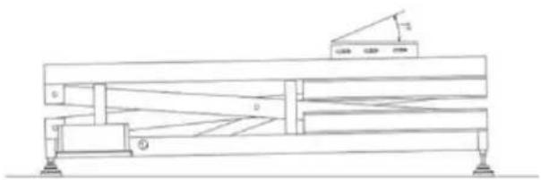
natural_image
Technical line drawing of a mechanical support structure with no visible text or symbolsnatural_image
Technical line drawing of a mechanical assembly with no visible text or symbols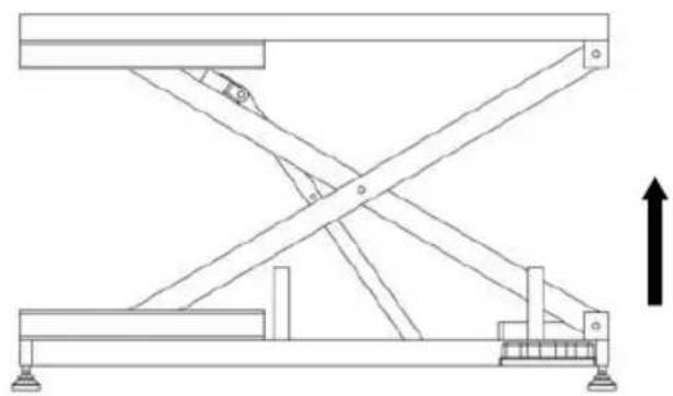
natural_image
Technical line drawing of a mechanical structure with beams and supports, no text or symbols presentDIMENSIONS AND PARAMETERS
Vänster dörr
Höger dörr

| Modell# | L(mm) | H(mm) | S(mm) | H1(mm) | H2(mm) | V(mm) | NV(kg) |
| K1E01027-U | 1270 | 1295 | 565 | 500 | 530 | 700 | 79,7 |
| K1E01028-U | 1270 | 1295 | 565 | 500 | 530 | 700 | 79,7 |
| K1E01027-E | 1270 | 1295 | 565 | 500 | 530 | 700 | 79,7 |
| K1E01028-E | 1270 | 1295 | 565 | 500 | 530 | 700 | 79,7 |
| K1E01027-A | 1270 | 1295 | 565 | 500 | 530 | 700 | 79,7 |
| K1E01028-A | 1270 | 1295 | 565 | 500 | 530 | 700 | 79,7 |
| Modell | K1E01027 -UK1E0102 8-U | K1E01027 -EK1E0102 8-E | K1E01027-AK1E01028-A |
| Dimensionera: | L1270xB700xH 1295 (min) | ||
| Resa | 560 mm | ||
| Lastkapacitet: | 1 50 kg/330 lb | ||
| Kontaktstandard | Amerikansk kontakt | eurokontakt | Australisk kontakt |
| Överbelastningsindikation | Ja | Ja | Ja |
| Driva: | 50W | 90W | 90W |
| Spänning: | AC1 20V | AC2 20–240 V | AC2 20–240 V |