FL-40 - Pump Vevor - Free user manual and instructions
Find the device manual for free FL-40 Vevor in PDF.

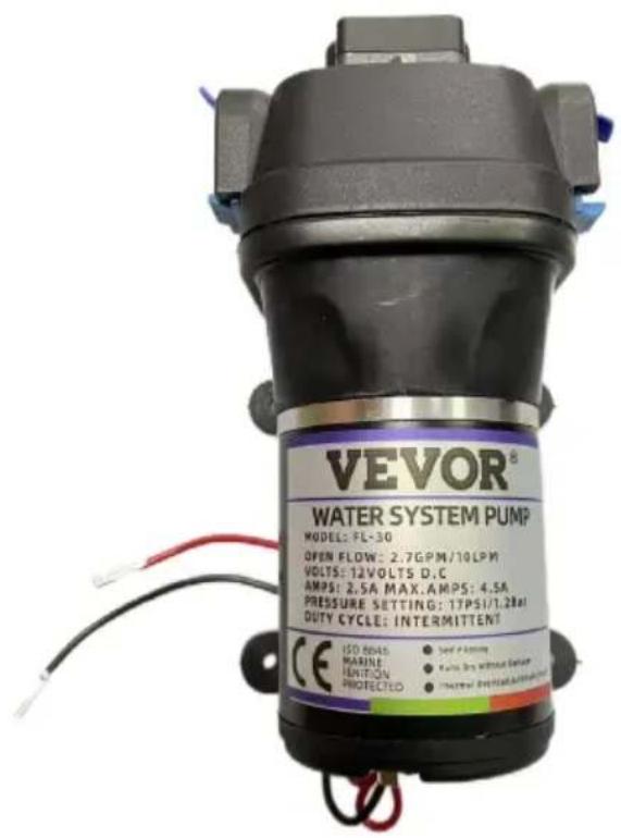
| Product Type | Self-priming diaphragm pump |
| Brand | Vevor |
| Model | FL-40 |
| Power Supply | 12 V DC, rated current 5.2 A, recommended fuse 30 A |
| Rated Flow Rate | 2.5 GPM (9.5 L/min) |
| Rated Pressure | 17 PSI (1.17 bar) |
| Maximum Discharge Head | 12 m |
| Maximum Suction Head | 2 m |
| Dry Running | Possible up to 10 minutes |
| Built-in Pressure Switch | Yes, adjustable |
| Bypass | Yes, adjustable (bypass screw) |
| Thermal Protection | Yes, automatic shutdown in case of overheating |
| Inlet/Outlet Connection | Reinforced hose 3/4" (19 mm) inner diameter |
| Materials | Motor, pump head, diaphragm, valves |
| Duty Cycle | Intermittent |
| Applications | Yacht water system, RV, caravan, spraying, cleaning, beverage filling |
| Installation | Vertical mounting with head down recommended, dedicated electrical circuit |
| Maintenance | Check seals, avoid obstructions, clean debris |
| Safety | Do not pump wastewater, do not immerse, use a 30 A fuse |
| Spare Parts | Head assembly, diaphragm, motor, valves, pressure switch |
| Repairability | Technical support and warranty at www.vevor.com/support |
Frequently Asked Questions - FL-40 Vevor
User questions about FL-40 Vevor
0 question about this device. Answer the ones you know or ask your own.
Ask a new question about this device
Download the instructions for your Pump in PDF format for free! Find your manual FL-40 - Vevor and take your electronic device back in hand. On this page are published all the documents necessary for the use of your device. FL-40 by Vevor.
USER MANUAL FL-40 Vevor
Technical Support and E-Warranty Certificate
www.vevor.com/support
Diaphragm Pump Manual
MODEL: FL-30 / FL-40
We continue to be committed to provide you tools with competitive price. "Save Half", "Half Price" or any other similar expressions used by us only represent estimate of savings you might benefit from buying certain tools with us compared top brands and does not necessarily mean to cover all categories of tools offered are kindly reminded to verify carefully when you are placing an order with us actually saving half in comparison with the top major brands.
MODEL: FL-30 / FL-40
NEED HELP? CONTACT US!
Have product questions? Need technical support? Please feel fr contact us:
Technical Support and E-Warranty Certificate www.vevor.com/support
This is the original instruction, please read all manual instruction carefully before operating. VEVOR reserves a clear interpretation user manual. The appearance of the product shall be subject to product you received. Please forgive us that we won't inform you there are any technology or software updates on our product.
 | Warning-To reduce the risk of injury, user must read instructions manual carefully. |
 | This product is subject to the provision of European 2012/19/EC. The symbol showing a wheelie bin cross through indicates that the product requires separate re collection in the European Union. This applies to the and all accessories marked with this symbol. Products marked as such may not be discarded with normal d waste, but must be taken to a collection point for re electrical and electronic devices |
FEATURES
- Run dry capable for normal workloads
- Self priming
- Intermittent duty
• Automatic: controlled by pressure switch - Quiet Operation
• Industry standard mounting pattern - Bypass: reduces cycling
• Thermal protection
APPLICABLE SCENE
- Yacht/RV/caravan pressurized water system
- Sprayer fixtures (vehicle-mounted sprayers, electric sprayers)
- Cleaning machines, humidifier, water purification, medical apparatus
- Food beverage filling & liquid transfer
- Solar water system
• Any other pressurization system
SPECIFICATION PARAMETERS
| Model | FL-30 | FL-40 |
| Input | DC12V | DC12V |
| Rated current | 5.2 A | 11 A |
| Rated flow | 2.5 GPM | 4.5 GPM |
| Rated pressure | 17 PSI | 40 PSI |
| Max lift | 12 m | 35 m |
| Max suction range | 2 m | 3 m |
INSTALLATION
Materials
1 diaphragm pump with related accessories
2 (at least) pieces of flexible, reinforced hose piping, with collapsing strength of twice the inlet collapsing pressure( hose must be minimum ID )
3 stainless steel hose clamps and screws
4 screws to fasten the pump to the mounting surface
1 electrical cutoff switch
1 fuse
1 screwdriver
1 strong cutting implement for tubing
(if desired) Teflon tape or sealant
Setup
-
The pump may be mounted in any position. If mounted vertically, the pump head should be in the down position to avoid leakage into the casing in the event of a malfunction.
-
Secure the feet, but do not compress them. Over tightening the sec screws may reduce their ability to dissipate noise and vibration.
-
Intake hose must be minimum 3/4" (19 mm) ID reinforced hose. Ma distribution line from pump outlet should also be 3/4" (19 mm) ID with branch and individual supply lines to outlets no smaller than 3/8" (10
-
Plumb the system using high pressure (2x pump rating), braided, fle tubing to minimize vibration/ noise.
-
Do not apply inlet pressure in excess of 30 psi. In general, try to any inlet pressure completely.
-
Avoid any kinks or fittings which could cause excessive restrictions.
7.Strainer should be attached to the inlet side.
-
The fittings must be secured to avoid leakage.
-
Use clamps at both ends of hose to prevent air leaks into the water
-
If a check valve is installed in the plumbing, it must have a cracking pressure of no more than 2 psi.
-
If applying a sealer or plumbing tape, be careful to not over tighter they may be sucked into pump.
-
This pump should be wired on its own dedicated circuit. Connect the positive lead (red) to the positive terminal of your battery and the negative wire (black) to the negative terminal of your battery.
-
In an easily accessible location, install a switch to control electricity the pump. Turn the pump off when not used for extended periods or the tank is empty.
-
The electrical circuit should be protected with an over-current protected device (fuse) in the positive lead. This pump requires a 30 amp fuse.
-
The pump circuit should not include any other electrical loads.
-
As the water supply pump is non-essential, reference the wire chart under the electrical information. Be sure to have the correct wire sizing the length of wire you are using.
-
After installation, check the voltage at the pump motor. Voltage should be checked when pump is operating. Full voltage must be available at the pump motor at all times.
ELECTRICALINFORMATION
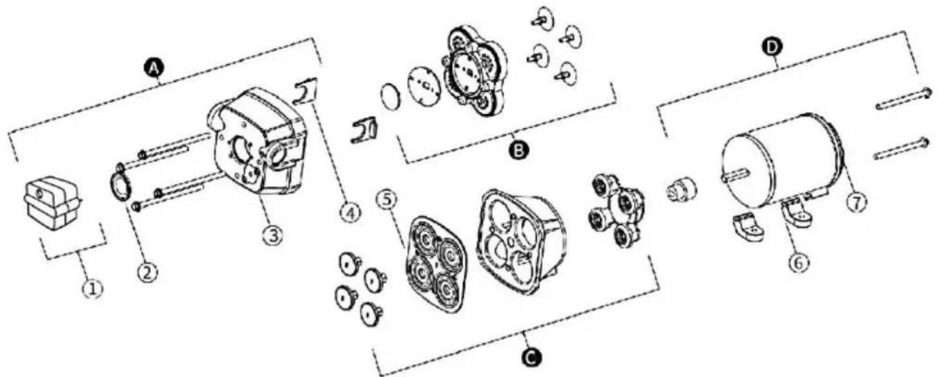
Pressure regulation function: The salient point in the pump head is equipped with the pressure switch, which can open the pressure switch cover, tighten in clockwise is to increase pressure, loosen in anti-clockwise is to reduce the pressure.
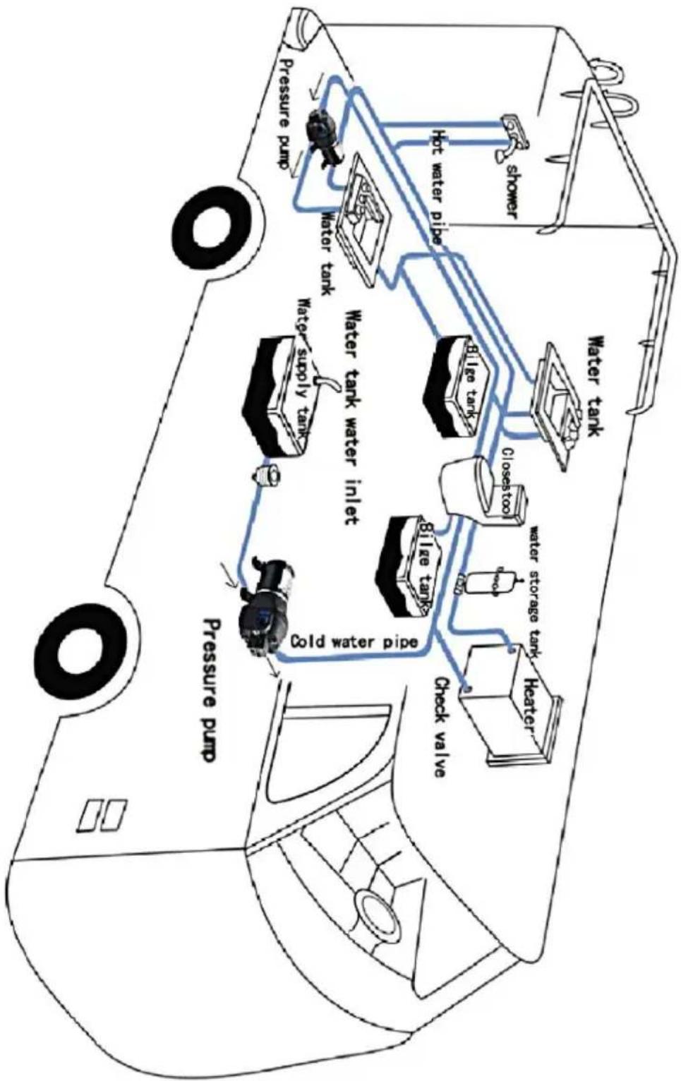
flowchart
graph TD
    A["Water tank"] --> B["Heater"]
    B --> C["Water storage tank"]
    C --> D["Closestool"]
    D --> E["Water tank"]
    E --> F["Water tank water inlet"]
    F --> G["Water tank"]
    G --> H["Water pump"]
    H --> I["Pressure pump"]
    I --> J["Check valve"]
    J --> K["Cold water pipe"]
    K --> L["Water supply tank"]
    L --> M["Water tank water inlet"]
    M --> N["Hot water pipe"]
    N --> O["Shower"]
SCHEMATIC DIAGRAM OF PARTS
| Key | Description | Quantity |
| A | Pump Head Assembly | 1 |
| B | Valve Assembly | 1 |
| C | Diaphragm Assembly | 1 |
| D | Motor Assembly | 1 |
| 1 | Pressure switch | 1 |
| 2 | Diaphragm of Pressure Switch | 1 |
| 3 | Pump Head | 1 |
| 4 | Quick Attach Clip | 2 |
| 5 | Diaphragm | 1 |
| 6 | Rubber Feet | 2 |
| 7 | Motor | 1 |
TROUBLESHOOTING
| PULSATING FLOW- PUMP CYCLES ON AND OFF | 1.The pipe equipment of water inlet or with a too small diameter. 2.Please check the joint is tightened, or the water outlet is in gas leak.3.Please check if the flexible pipe of wa outlet is knotted or bending. 4.Check if t exist pump blocked operation, please try keep smooth drainage. |
| FAILURE TO PRIME BUT MOTOR OPERATES NO PUMP DISCHARGE | 1.Restricted intake or discharge line.Air leak in intake line.2.Punctured pump diaphragm.Initial amp supply is not enough to suffi start the motor.3.Debris clogged in the valves.4.Crack in pump housing. |
| MOTOR FAILS TO TURN OF | 1.Loose or improper wiring.2.Pump circuit has no power.3.Blown fuse or thermal protection tripped4.Failed pressure switch.5.Defective motor. |
| PUMP FAILS TO TURN OFF AFTER ALL FIXTURES ARE CLOSED | 1.Punctured diaphragm.2.Discharge line leak.3.Defective pressure switch.4.Insufficient voltage.5.Clogged valves in pump head. |
| LOW FLOW AND PRESSUR | 1.Air leak at pump intake.2.Accumulation of debris inside pump or plumbing.3.Worn pump bearing (possibly accompani by loud noise).4.Punctured diaphragm5.Defective motor. |
| NOISY | 1.Check if the mounting feet are compres too tightly.2.Is the mounting surface flexible? If so, may be adding noise.3.Check for loose head/screws.4.If the pump is plumbed with rigid pipe it may transmit noise more easily. |
ABOUT THE BYPASS
Please consult a professional technician in the case that the bypass adjustment. Improper adjustment of the bypass may damage the pump. The bypass comes preset for optimal operation of the pump. If your application calls for a different setting for the bypass, you may change yourself. Carefully tighten the screw to increase or loosen the screw to decrease the minimum operational pressure of the bypass.
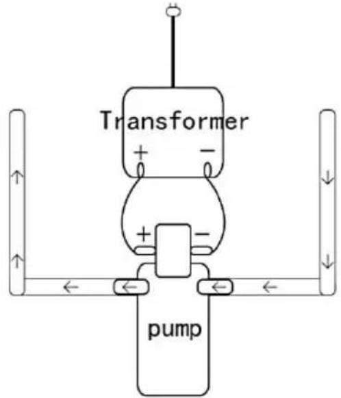
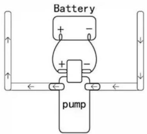
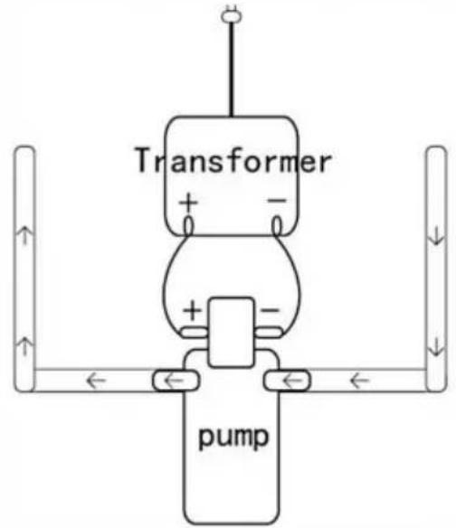
CONNECTION METHOD OF 12 V OR 24 V PUMP (BATTERY OR TRANSFOR
Connection method of Battery
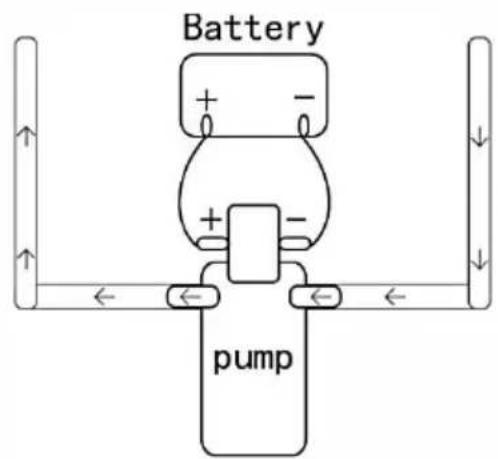
Connection method of Transformer
Caution
-
It is need to ensure the smooth water yield when the water pump working, to avoid the damage of pressure switch due to the pump b operation!
-
Although the water pump support the dry operating in short time, pl not to exceed 10 Mi nut es!
-
It is self-absorption diaphragm pump which with slight waterproof function, please do not put it in to water directly!
-
It is clean water pump, please do not pump the sewage with impu avoid the block of pump head!
-
It is normal that the motor is hot when the pump in use, because TEMP control protector was built-in, it will automatically stop working with the TEMP reaches a certain degree Celsius, please feel free to use
Made In China
VEVOR®
TOUGH TOOLS, HALF PRICE
Technical Support and E-Warranty Certificate
www.vevor.com/support
VEVOR®
TOUGH TOOLS, HALF PRICE
Assistance technique et certificat garantie
www.vevor.com/support
flowchart
graph TD
    A["Water tank"] --> B["Water supply tank"]
    B --> C["Water tank water inlet"]
    C --> D["Cold water pipe"]
    D --> E["Pressure pump"]
    E --> F["Heater"]
    F --> G["Water storage tank"]
    G --> H["Water tank"]
    H --> I["Shower"]
    I --> J["Hot water pipe"]
    J --> K["Water tank water inlet"]
    K --> L["Pressure pump"]
    L --> M["Check valve"]

Connection method of Battery
Connection method of Transformer

Prudence
www.vevor.com/support
flowchart
graph TD
    A["Water tank"] --> B["Water supply tank"]
    B --> C["Water tank water inlet"]
    C --> D["Cold water pipe"]
    D --> E["Pressure pump"]
    E --> F["Heater"]
    F --> G["Water storage tank"]
    G --> H["Water tank"]
    H --> I["Shower"]
    I --> J["Hot water pipe"]
    J --> K["Water tank water inlet"]
    K --> L["Pressure pump"]
    L --> M["Check valve"]

Connection method of Battery

Connection method of Transformer

Vorsicht
www.vevor.com/support
VEVOR®
TOUGH TOOLS, HALF PRICE
elettronica www.vevor.com/support
flowchart
graph TD
    A["Water tank"] --> B["Water supply tank"]
    B --> C["Water tank water inlet"]
    C --> D["Cold water pipe"]
    D --> E["Pressure pump"]
    E --> F["Heater"]
    F --> G["Water storage tank"]
    G --> H["Water tank"]
    H --> I["Shower"]
    I --> J["Hot water pipe"]
    J --> K["Water tank water inlet"]
    K --> L["Pressure pump"]
    L --> M["Check valve"]
SCHEMA DELLEPARTI

Connection method of Battery

Connection method of Transformer

Attenzione
flowchart
graph TD
    A["Water tank"] --> B["Water supply tank"]
    B --> C["Water tank water inlet"]
    C --> D["Cold water pipe"]
    D --> E["Pressure pump"]
    E --> F["Heater"]
    F --> G["Water storage tank"]
    G --> H["Water tank"]
    H --> I["Shower"]
    I --> J["Hot water pipe"]
    J --> K["Water tank water inlet"]
    K --> L["Pressure pump"]
    L --> M["Check valve"]

Connection method of Battery

Connection method of Transformer

Precaución
flowchart
graph TD
    A["Water tank"] --> B["Water tank water inlet"]
    B --> C["Water tank"]
    C --> D["Water tank"]
    D --> E["Heater"]
    E --> F["Water storage tank"]
    F --> G["Closestool"]
    G --> H["Water tank"]
    H --> I["Heater"]
    I --> J["Water tank"]
    J --> K["Hot water pipe"]
    K --> L["Pressure pump"]
    L --> M["Pressure pump"]
    M --> N["Water supply tank"]
    N --> O["Cold water pipe"]
    O --> P["Check valve"]

Connection method of Battery

Connection method of Transformer

Ostrożność
www.vevor.com/support
HULP NODIG? NEEM CONTACT MET ONS OP!
flowchart
graph TD
    A["Water tank"] --> B["Water supply tank"]
    B --> C["Water tank water inlet"]
    C --> D["Cold water pipe"]
    D --> E["Pressure pump"]
    E --> F["Heater"]
    F --> G["Water storage tank"]
    G --> H["Water tank"]
    H --> I["Shower"]
    I --> J["Hot water pipe"]
    J --> K["Water tank"]
    K --> L["Pressure pump"]
    L --> M["Check valve"]

Connection method of Battery

Connection method of Transformer

www.vevor.com/support
Membranpumpmanual
MODELL: FL-30 / FL-40
flowchart
graph TD
    A["Water tank"] --> B["Water tank water inlet"]
    B --> C["Water supply tank"]
    C --> D["Pressure pump"]
    D --> E["Cold water pipe"]
    E --> F["Heater"]
    F --> G["Water storage tank"]
    G --> H["Water tank"]
    H --> I["Shower"]
    I --> J["Hot water pipe"]
    J --> K["Water tank"]
    K --> L["Pressure pump"]
    L --> M["Check valve"]
SCHEMATISK DIAGRAM ÖVERDELAR

Connection method of Battery

Connection method of Transformer
Försiktighet
www.vevor.com/support