C110 - Measuring equipment Vevor - Free user manual and instructions
Find the device manual for free C110 Vevor in PDF.

| Product Type | Tire Pressure Monitor (TPMS) |
| Model | C110 |
| Brand | Vevor |
| Power Supply | 12 V DC (cigarette lighter) |
| Power Consumption | 0.03 W |
| Pressure Measurement Range | 0.5 to 6 bar (7.25 to 87 psi) |
| Net Weight | 0.1 kg |
| Number of Sensors | 4 (one per tire) |
| Display | LCD, simultaneous display of all 4 pressures and temperatures |
| Adjustable Units | bar/psi, °C/°F |
| Main Functions | Pressure and temperature monitoring, visual and audible alarms, intelligent sleep mode, leak detection |
| Adjustable Alarm Thresholds | High pressure (0.6-6 bar), low pressure (0.5-5.9 bar), high temperature (50-99 °C) |
| Sensor Type | External (screws onto valve) |
| Installation | Screw sensors onto valves, plug receiver into cigarette lighter |
| Pairing | Automatic while driving >20 km/h, or manual via SET button |
| Maintenance | Clean with a dry soft cloth; avoid chemicals |
| Safety | Complies with FCC Part 15; do not modify without authorization |
| Replaceable Parts | Sensors (integrated batteries) |
| Warranty | Via www.vevor.com/support |
Frequently Asked Questions - C110 Vevor
User questions about C110 Vevor
0 question about this device. Answer the ones you know or ask your own.
Ask a new question about this device
Download the instructions for your Measuring equipment in PDF format for free! Find your manual C110 - Vevor and take your electronic device back in hand. On this page are published all the documents necessary for the use of your device. C110 by Vevor.
USER MANUAL C110 Vevor
Technical Support and E-Warranty Certificate www.vevor.com/support
TPMS
MODEL:C110
We continue to be committed to provide you tools with competitive price. "Save Half", "Half Price" or any other similar expressions used by us only repressor estimate of savings you might benefit from buying certain tools with us compared to top brands and does not necessarily mean to cover all categories of tools offered by are kindly reminded to verify carefully when you are placing an order with us if you actually saving half in comparison with the top major brands.
MODEL:C110

NEED HELP? CONTACT US!
Have product questions? Need technical support? Please feel free contact us:
Technical Support and E-Warranty Certificate www.vevor.com/support
This is the original instruction, please read all manual instructions carefully before operating. VEVOR reserves a clear interpretation of user manual. The appearance of the product shall be subject to the product you received. Please forgive us that we won't inform you there are any technology or software updates on our product.
PARAMETER LIST
| Model | C110 |
| Voltage | DC 12V |
| Power | 0.03W |
| Test The Tire Pressure Range (Bar) | 0.5-6 |
| Net Weight (Kg) | 0.1 |
PART LIST
| Name | Picture | Quantity |
| Wrench | 1 | |
| Nut | 4 | |
| Sensor |  | 4 |
| Host |  | 1 |
OPERATION
1. FEATURES
- Monitor the pressure and temperature of your tyres
-
Intelligent sleeping mode for power saving
-
Tyre leaking warning
- Visual and audible warning for abnormal tyre pressure and temperature
- Displays up to 4 tyres temperature and pressure at a glance
- Can be set to Fixed Bar Or PSI
- Can be set to °C or °F temperature
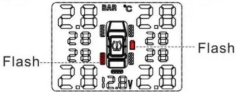
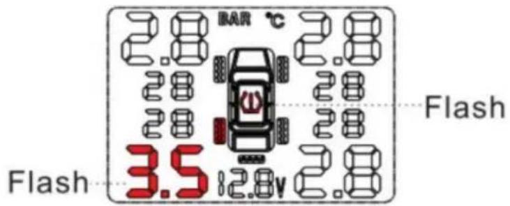
2. Structure
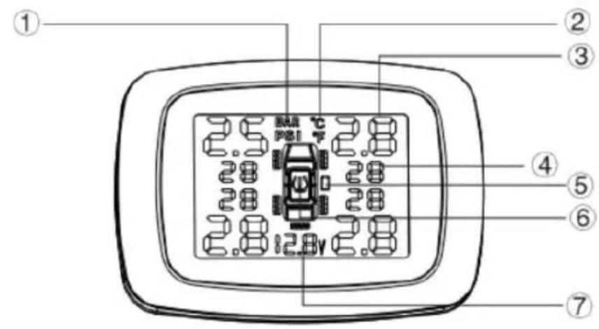
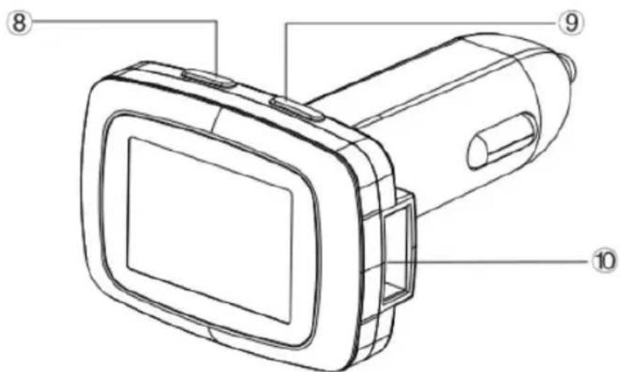
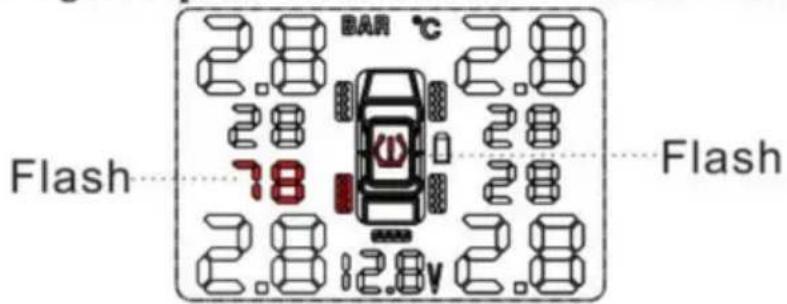
- Pressure unit
- Pressure data
5.Sensor battery indicator
7.Input voltage
9.(+) Button
2.Temperature unit
4.Temperature data
6. Warning signs
8."SET"Button
10.USB port
3. PARAMETER SETTING REFERENCE
- Before using this product, please press any button on the display to turn on i charge the display for 3-4 hours with the cigarette plug charger.
- Factory default parameter setting
| Factory default setting | Parameter setting range |
| HI pressure alarm data: 3.0Bar | 0.6-6.0 Bar |
| low pressure alarm data:2.0Bar | 0.5-5.9 Bar |
| HI temperature alarm data: 68°C | 50-99°C |
- 1Bar=14.5Psi
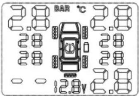
- When the ACC ON, the display will get into self-test mode for 2 seconds. After 2 seconds, all icons will be displayed on the LCD screen, and ready to receive new data. When the ACC OFF, the display will be OFF.
- When the speed up to 20 kilometers per hour, the sensor will be activated, a start to detect and send the Pressure and temperature data.
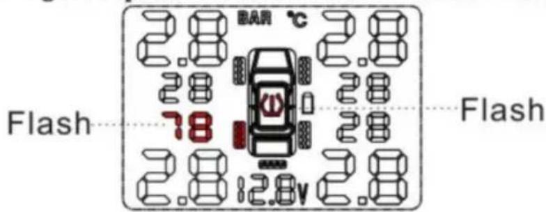
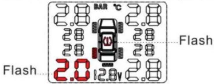
- Alarming instruction
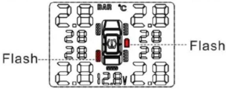
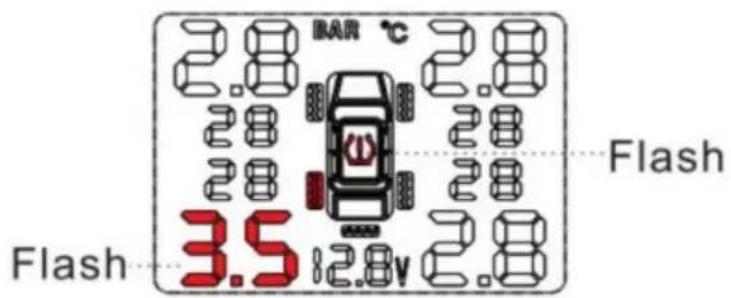
a) When tyre pressure over the set range or tyre is leaking, the corresponding ty position icon , pressure data and the alarm icon (!) will flash together, and the built-in buzzer will chirp as: Bi Bi ·. Note: press any button can stop the buzzer, all corresponding icons still flash, buzzer will chirp once per minute.
b). When tyre temperature over the set data, the according tyre position icon temperature data and high temperature alarm icon (!) will flash together, and the built-in buzzer will chirp as: Bi Bi.
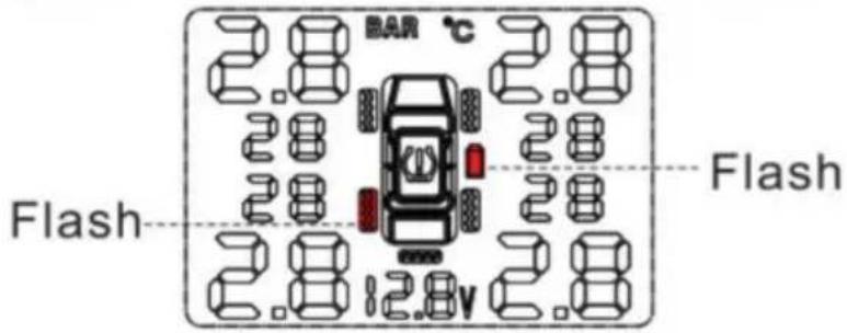
c). When sensor battery is low, the icon * of the corresponding tyre position, sensor low battery icon will flash together, and the built-in buzzer will chirp as: E Bi. Note: To stop the buzzer, press the set buzzer, note - all icons will still flash
buzzer will "Chirp" once per minute.
5. ALARM STATUS
Leaking or low tyre pressure alarm

Bi.Bi.
Eg:L.R. tyre leaking or low tyre pressure alarm. The corresponding tyre position icon, pressure data and the alarm icon will flash together.

High tyre pressure alarm

Bi.Bi.
Set range:1.7\~3. 4Bar Eg:L.R. tyre high pressure alarm. The corresponding tyre position icon ☐, pressure data and the alarm icon ☑ will flash together.

High tyre temperature alarm

Bi.Bi.
Factory default setting: 70°C Eg: L. R. tyre high temperature alarm. Temperature data and high temperature alarm icon will flash together.
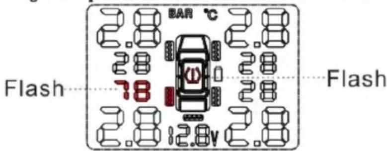
Sensor low battery

Bi.Bi.
Sensor battery normal life:3-5 years Eg:L.R.Tyre high temperature alarm. The according tyre position icon, sensor low battery icon will flash together.
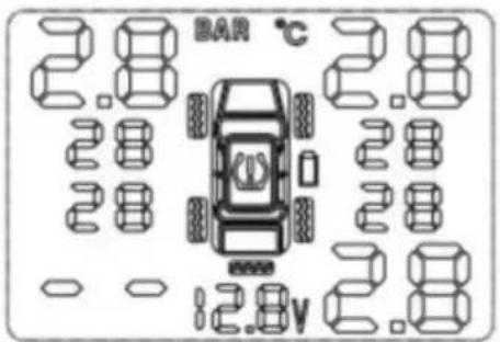
Sensor not work

Bi.Bi.
Eg:L.R.tyre sensor not work the corresponding tyre position icon ☐, pressure data and the temperature will disappear together
6. WORK PARAMETER SETTING OPERATION
1. Enter and quit setting mode:
Press “ SET ” button and hold on for 3 seconds, release the button after hearing long chirp, the monitoring system will enter the setting mode. Press the “ SET ” button short time to recycle among the following settings: Bar-Psi,C >F, pressure HI, pressure LO, alarm temperature HI. Press the (+) button to adjust corresponding data. After finishing all settings, press the “ SET ” button and hold on for 3 seconds, after hearing I short chirp, the system save all set parameters and quit the setting mode.
(Note: After entering the setting mode, if there is no operation within 3 minute, the system will quit the mode and back to normal working mode automatically)
2. Tyre pressure HI setting:
Press and hold on the “ SET ” button for 3 seconds, release the button after hearing 1 long chirp, will enter into the setting mode.
Then press the (+) button one by one to get into tyre pressure HI setting mode. The pressure HI data flash, press the (+) button to adjust the data, then press the “SET” button and hold on for 3 seconds, release the button after hearing I sh chirp, the system save the set data and quit the mode.
(Note: the set pressure HI data must be higher than the set pressure LO data. Pressure HI adjustable range: 0.6-6.0 Bar. Factory default setting: 3.0Bar)
-
Tyre pressure LO setting: Press and hold on the (+) button for 3 sec Release the button after hearing1 long chirp, the system enter the setting mode, Then press the “SET” button one by one to enter into tyre pressure LO setting status. The pressure LO data will flash press the (+) button to adjust the data, t press the “SET” button and hold for3 seconds, release the button after hearing short chirp, the system save the set data and quit the mode. (Note: the set pressure LO data must be lower than the set pressure HI data, Pressure LO adjustable range: 0.5-5.9 Bar, Factory default setting: 2.0Bar)
-
Release the button after hearing1 long chirp, the system enter the setting mode. Then press the (+) button one by one to get into alarm temperature HI setting status, the icon will flash, press the RIGH'T button to adjust the data, then press the button and hold on for 3 seconds, release the button after hearing I short chirp, the system save the set data and quit the mode.
(Note: temperature HI adjustable range: 50 °C - 99 °C Factory default setting: 68 °C )
-
Pressure unit setting: Press and hold on the (+) button for 3 seconds, rele the button after hearing1 long chirp, the system enter pressure unit setting mode. The Bar icon will flash, press the (+) button to adjust the unit, then press the set button and hold on for 3 seconds, release the button after hearing I short chirp, system save the set data and quit the mode. (Factory default setting: Bar)
-
Temperature unit setting: Press and hold on the (+) button for 3 seconds, release the button after hearing1 long chirp, the system enter into the setting mo Then press the (+) button one by one to get into temperature unit setting status. The C icon will flash, press the ( ) button to adjust the data, then press the but
and hold on for 3 seconds, release the button after hearing I short chirp, the system save the set data and quit the mode.
- Tyre pressure code matching Long press the (+) button for 3 seconds and release it after hearing a long “Bi” to enter the tyre pressure code matching mode, the left front wheel icon and “_.” fash press the “SET” button to select the tyre be matched, and the corresponding tyre after selection “_.” will flashing, at this time, inflate the corresponding tyre (The external sensor is directly screwed to the valve), after receiving the signal “_.” changes to the pressure value to indicate that the matching is successful, then short press the (+) button to jump to the next type. Follow the previous step to match other tyres, After matching, press and hold the (+) button for 3 seconds, save and exit after a “Bi” (Entering the tyre matching mode without any action, the matching mode will automatically exit after 3 minutes). (Note: The sensor and receiver have been matched before leaving the factory, and the sensor or receiver needs to be re-matched to change the sensor or receiver.
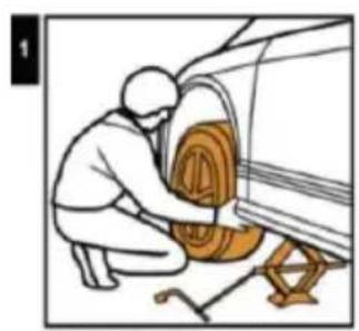
INTERNAL SENSOR INSTALLATION
natural_image
Illustration of a person installing or repairing a car wheel assembly (no text or symbols visible)Jack up the car and de-mount the tire.
natural_image
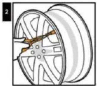
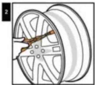
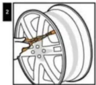
Illustration of a car wheel with a tool inserted, showing the wheel rim and center (no text or symbols)Remove original valve.

natural_image
Illustration of a wooden object partially covered by coiled wires (no text or symbols)Tighten up screw

natural_image
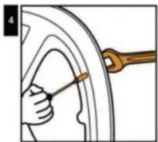
Illustration of a hand holding a tool interacting with a curved surface (no text or symbols)Install the tire from left side of the valve clockwise direction, avoid tire bead hits valve and sensor.
natural_image
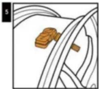
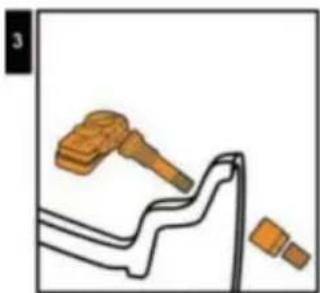
Illustration of a hammer and nail on a surface with a wavy line and two small blocks nearby (no text or symbols)Sensor Assemble
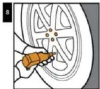
natural_image
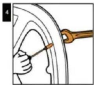
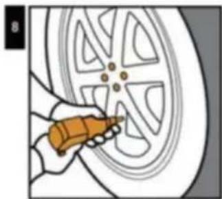
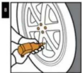
Illustration of a car wheel being adjusted with a wrench (no text or symbols)Tighten the valve by wrench and screw it ( Torque value must be ≥ 4Nm)
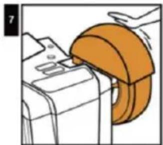
natural_image
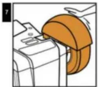
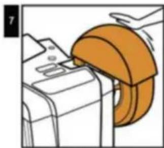
Illustration of a hand using a mechanical tool to lift a component (no text or symbols visible)Balance the tire.
natural_image
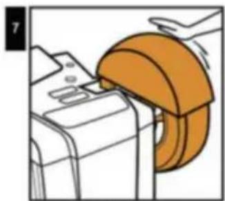
Illustration of a hand using a tool to clean or repair a car tire (no text or symbols visible)Mount the tire to it's position.
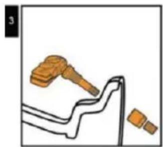
External sensor installation

natural_image
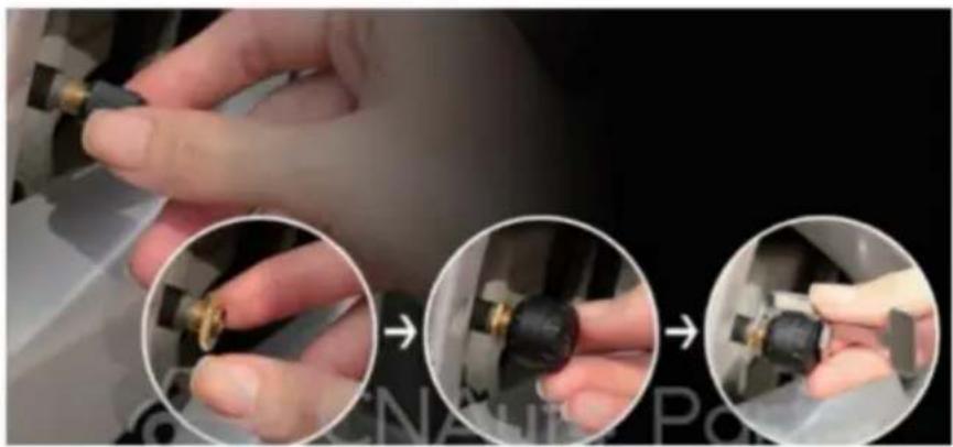
Close-up of hands adjusting a mechanical component, showing three sequential steps (no text or symbols visible)- Unscrew the valve cap.
- Screw in the nut.
- Screw in the sensor.
- Lock the sensor with an anti-theft wrench.
Movement / Replacement of battery
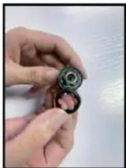
natural_image
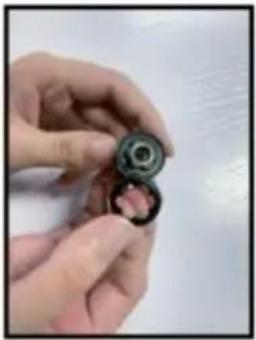
Close-up of hands holding a ball bearing and a small object, no visible text or symbols- Peel off the non-slip gasket
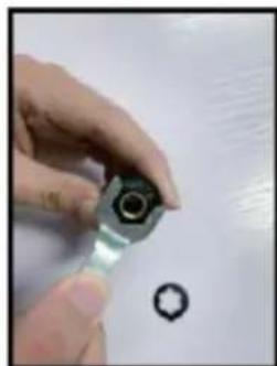
natural_image
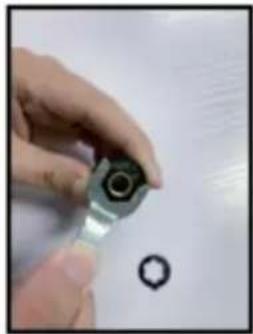
Close-up of a hand holding a small metallic mechanical component with a hole, next to a separate circular hole (no text or symbols visible)- Unscrew the sensor with a wrench
| ITEM\UNIT | SENSOR | DISPLAY | |
| Working frequency | 433.9200MHz±0.1MHz | ||
| Workong voltage | 2.0~3.6V | 12-24V | |
| Working current | static current≤1uA | static current≤0uA | |
| Dynamic≤15mA | Dynamic≤30mA | ||
| Working environment | Temperature | -40°C~+125°C | -40°C~+70°C |
| Monitoring scope | Temperature | 50-99bar | |
| Pressure | 0-6 bar 0 psi~72.5 psi | ||
FCC Information:
CAUTION: Changes or modifications not expressly approved by the party responsible for compliance could void the user's authority to operate the equipment!
This device complies with Part 15 of the FCC Rules. Operation is subject to the following two conditions:
1) This product may cause harmful interference.
2) This product must accept any interference received, including interference that may cause undesired operation.
WARNING: Changes or modifications to this product not expressly approved by the party. responsible for compliance could void the user's authority to operate the product.
Note: This product has been tested and found to comply with the limits for a Class B digital device pursuant to Part 15 of the FCC Rules, These limits are designed to provide reasonable protection against harmful interference in a residential installation.
This product generates, uses and can radiate radio frequency energy, and if not installed and used in accordance with the instructions, may cause harmful interference to radio communications. However, there is no guarantee that
interference will not occur in a particular installation. If this product does cause harmful interference to radio or television reception, which can be determined by turning the product off and on, the user is encouraged to try to correct the interference by one or more of the following measures.
- Reorient or relocate the receiving antenna.
- Increase the distance between the product and receiver.
- Connect the product to an outlet on a circuit different from that to which the receiver is connected.
- Consult the dealer or an experienced radio/TV technician for assistance.
CORRECT DISPOSAL
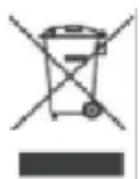
This product is subject to the provision of European Directive 2012/19/EU. The symbol showing a wheelie bin crossed through indicates that the product requires separate refuse collection in the European Union. This applies to the product and all accessories
marked with this symbol. Products marked as such may not be discarded with normal domestic waste, but must be taken to a collection point for recycling electrical and electronic devices.
Manufacturer: Shanghaimuxinmuyeyouxiangongsi
Address: Shuangchenglu 803nong11hao1602A-1609shi, baoshanqu, shanghai 200000 CN.
Imported to AUS: SIHAO PTY LTD. 1 ROKEVA STREETEASTWOOD NSW 212 Australia
Imported to USA: Sanven Technology Ltd. Suite 250, 9166 Anaheim Place, Rancho Cucamonga, CA 91730
| UK | REP |
YH CONSULTING LIMITED.
C/O YH Consulting Limited Office 147,
Centurion House, London Road,
Staines-upon-Thames, Surrey, TW18 4AX
| EC | REP |
E-CrossStu GmbH
Mainzer Landstr.69,
60329 Frankfurt am Main.
VEVOR®
TOUGH TOOLS, HALF PRICE
Technical Support and E-Warranty Certificate
www.vevor.com/support
VEVOR®
TOUGH TOOLS, HALF PRICE
BESOIN D'AIDE ? CONTACTEZ-NOUS!
- Pressure unit
- Pressure data
5.Sensor battery indicator
7.Input voltage
9.(+) Button
2.Temperature unit
4.Temperature data
6.Warning signs
8."SET"Button
10.USB port
3. RÉFÉRENCE DE RÉGLAGE DES PARAMÈTRES
Leaking or low tyre pressure alarm

Bi.Bi.
Eg:L.R. tyre leaking or low tyre pressure alarm. The corresponding tyre position icon, pressure data and the alarm icon will flash together.

High tyre pressure alarm

Bi.Bi.
Set range:1.7\~3. 4Bar Eg:L.R. tyre high pressure alarm. The corresponding tyre position icon ☐, pressure data and the alarm icon ☑ will flash together.
High tyre temperature alarm

Bi.Bi.
Factory default setting: 70°C Eg: L. R. tyre high temperature alarm. Temperature data and high temperature alarm icon will flash together.

Sensor low battery

Bi.Bi.
Sensor battery normal life:3-5years Eg:L.R.Tyre high temperature alarm. The according tyre position icon ☐, sensor low battery icon — will flash together.
Sensor not work

Bi.Bi.
Eg:L.R. tyre sensor not work the corresponding tyre position icon ☐, pressure data and the temperature will disappear together
6. OPÉRATION DE RÉGLAGE DES PARAMÈTRES DE TRAVAIL
natural_image
Person washing a car with a hose, no text or symbols visibleJack up the car and de-mount the tire.

natural_image
Illustration of a car wheel with a hand holding a tool, showing internal components (no text or symbols)Remove original valve.

natural_image
Illustration of a sandwich with a sandwich block and rope, no text or symbols presentTighten up screw

natural_image
Illustration of a hand holding a tool interacting with a circular object, no text or symbols presentInstall the tire from left side of the valve clockwise direction, avoid tire bead hits valve and sensor.

natural_image
Illustration of a wooden hammer striking a piece of wood, with no visible text or symbolsSensor Assemble

natural_image
Illustration of a hand using a wrench to measure a car wheel rim (no text or symbols present)Tighten the valve by wrench and screw it ( Torque value must be ≥ 4Nm)

natural_image
Illustration of a hand using a tool to lift a mechanical component (no text or symbols visible)Balance the tire.
natural_image
Illustration of a hand using a tool to clean the car wheel rim (no text or symbols visible)Mount the tire to it's position.
External sensor installation
natural_image
Close-up of hands adjusting a mechanical component, showing three sequential steps (no text or symbols visible)- Unscrew the valve cap.
- Screw in the nut.
- Screw in the sensor.
- Lock the sensor with an anti-theft wrench.
Movement / Replacement of battery

natural_image
Close-up of hands holding a small mechanical component, possibly a bearing or ball, with no visible text or symbols.- Peel off the non-slip gasket

natural_image
Close-up of a hand holding a small metallic component with a hole, next to a small circular mark (no text or symbols visible)- Unscrew the sensor with a wrench
| ITEM\UNIT | SENSOR | DISPLAY | |
| Working frequency | 433.9200MHz±0.1MHz | ||
| Workong voltage | 2.0~3.6V | 12-24V | |
| Working current | static current≤1uA | static current≤0uA | |
| Dynamic≤15mA | Dynamic≤30mA | ||
| Working environment | Temperature | -40°C~+125°C | -40°C~+70°C |
| Monitoring scope | Temperature | 50-99bar | |
| Pressure | 0-6 bar 0 psi~72.5 psi | ||
Informations FCC :
C/O YH Consulting Limited Bureau 147,
Centurion House, London Road,
Staines-upon-Thames, Surrey, TW18 4AX
E-CrossStu GmbH
Mainzer Landstr.69,
- Pressure unit
- Pressure data
5.Sensor battery indicator
7.Input voltage
9.(+) Button
2.Temperature unit
4.Temperature data
6. Warning signs
8."SET"Button
10.USB port
3. PARAMETEREINSTELLUNGSREFERENZ
Leaking or low tyre pressure alarm

Bi.Bi.
Eg:L.R. tyre leaking or low tyre pressure alarm. The corresponding tyre position icon, pressure data and the alarm icon will flash together.

High tyre pressure alarm

Bi.Bi.
Set range:1.7\~3. 4Bar Eg:L.R. tyre high pressure alarm. The corresponding tyre position icon ☐, pressure data and the alarm icon ☑ will flash together.

High tyre temperature alarm

Bi.Bi.
Factory default setting: 70°C Eg: L. R. tyre high temperature alarm. Temperature data and high temperature alarm icon will flash together.
Sensor low battery

Bi.Bi.
Sensor battery normal life:3-5years Eg:L.R.Tyre high temperature alarm. The according tyre position icon ☐, sensor low battery icon — will flash together.

Sensor not work

Bi.Bi.
Eg:L.R. tyre sensor not work the corresponding tyre position icon ☐, pressure data and the temperature will disappear together

natural_image
Illustration of a person washing a car with a hose and wooden stand (no text or symbols)Jack up the car and de-mount the tire.

natural_image
Illustration of a car wheel with a hand holding a tool, showing internal components (no text or symbols)Remove original valve.

natural_image
Illustration of a brown object partially enclosed by coiled white lines, no text or symbols presentTighten up screw

natural_image
Illustration of a hand holding a tool interacting with a circular object, no text or symbols presentInstall the tire from left side of the valve clockwise direction, avoid tire bead hits valve and sensor.

natural_image
Illustration of a hammer striking a piece of wood, with no visible text or symbolsSensor Assemble

natural_image
Illustration of a car wheel with a wrench and a tool inserted, no text or symbols presentTighten the valve by wrench and screw it ( Torque value must be ≥ 4Nm)
natural_image
Illustration of a hand using a mechanical tool to lift a component, showing orange ring and base (no text or symbols)Balance the tire.

natural_image
Illustration of a hand using a tool to clean or repair a car tire (no text or symbols visible)Mount the tire to it's position.
External sensor installation

natural_image
Close-up of hands adjusting a mechanical component, showing three sequential steps (no text or symbols visible)- Unscrew the valve cap.
- Screw in the nut.
- Screw in the sensor.
- Lock the sensor with an anti-theft wrench.
Movement / Replacement of battery

natural_image
Close-up of hands holding a small mechanical component, possibly a bearing or ball, with no visible text or symbols.- Peel off the non-slip gasket
natural_image
Close-up of a hand holding a small metallic component with a hole, next to a small circular mark (no text or symbols visible)- Unscrew the sensor with a wrench
| ITEM\UNIT | SENSOR | DISPLAY | |
| Working frequency | 433.9200MHz±0.1MHz | ||
| Workong voltage | 2.0~3.6V | 12-24V | |
| Working current | static current≤1uA | static current≤0uA | |
| Dynamic≤15mA | Dynamic≤30mA | ||
| Working environment | Temperature | -40°C~+125°C | -40°C~+70°C |
| Monitoring scope | Temperature | 50-99bar | |
| Pressure | 0-6 bar 0 psi~72.5 psi | ||
FCC-Informationen:
C/O YH Consulting Limited Office 147,
Centurion House, London Road,
Staines-upon-Thames, Surrey, TW18 4AX
www.vevor.com/support
VEVOR®
TOUGH TOOLS, HALF PRICE
- Pressure unit
- Pressure data
5.Sensor battery indicator
7.Input voltage
9.(+) Button
2.Temperature unit
4.Temperature data
6.Warning signs
8."SET"Button
10.USB port
3. RIFERIMENTO IMPOSTAZIONE PARAMETRI
Leaking or low tyre pressure alarm

Bi.Bi.
Eg:L.R. tyre leaking or low tyre pressure alarm. The corresponding tyre position icon, pressure data and the alarm icon will flash together.

High tyre pressure alarm

Bi.Bi.
Set range:1.7\~3. 4Bar Eg:L.R. tyre high pressure alarm. The corresponding tyre position icon ☐, pressure data and the alarm icon ☑ will flash together.

High tyre temperature alarm

Bi.Bi.
Factory default setting: 70°C Eg: L. R. tyre high temperature alarm. Temperature data and high temperature alarm icon will flash together.

Sensor low battery

Bi.Bi.
Sensor battery normal life:3-5years Eg:L.R.Tyre high temperature alarm. The according tyre position icon ☐, sensor low battery icon — will flash together.
Sensor not work

Bi.Bi.
Eg:L.R. tyre sensor not work the corresponding tyre position icon ☐, pressure data and the temperature will disappear together

natural_image
Person washing a car with a hose, no text or symbols visibleJack up the car and de-mount the tire.
natural_image
Illustration of a car wheel with a hand holding the rim, showing mechanical components (no text or symbols)Remove original valve.

natural_image
Illustration of a sandwich with a sandwich block and rope, no text or symbols presentTighten up screw

natural_image
Illustration of a hand holding a tool interacting with a circular object, no text or symbols presentInstall the tire from left side of the valve clockwise direction, avoid tire bead hits valve and sensor.

natural_image
Illustration of a wooden hammer striking a piece of wood, with a separate piece nearby (no text or symbols)Sensor Assemble

natural_image
Illustration of a hand using a wrench to measure a car wheel rim (no text or symbols present)Tighten the valve by wrench and screw it ( Torque value must be ≥ 4Nm)

natural_image
Illustration of a hand using a tool to lift a mechanical component (no text or symbols visible)Balance the tire.

natural_image
Illustration of a hand using a tool to clean the wheel rim (no text or symbols visible)Mount the tire to it's position.
External sensor installation

natural_image
Close-up of hands adjusting a mechanical component with three circular insets showing progressive assembly (no text or symbols visible)- Unscrew the valve cap.
- Screw in the nut.
- Screw in the sensor.
- Lock the sensor with an anti-theft wrench.
Movement / Replacement of battery

natural_image
Close-up of hands holding a small mechanical component, possibly a bearing or ball, with no visible text or symbols.- Peel off the non-slip gasket

natural_image
Close-up of a hand holding a small metallic component with a hole, next to a small circular mark (no text or symbols visible)- Unscrew the sensor with a wrench
| ITEM\UNIT | SENSOR | DISPLAY | |
| Working frequency | 433.9200MHz±0.1MHz | ||
| Workong voltage | 2.0~3.6V | 12-24V | |
| Working current | static current≤1uA | static current≤0uA | |
| Dynamic≤15mA | Dynamic≤30mA | ||
| Working environment | Temperature | -40°C~+125°C | -40°C~+70°C |
| Monitoring scope | Temperature | 50-99bar | |
| Pressure | 0-6 bar 0 psi~72.5 psi | ||
Informazioni FCC:
Importato in AUS: SIHAO PTY LTD. 1 ROKEVA STREETEASTWOOD NSW 2122 Australia
C/O YH Consulting Limited Office 147,
Centurion House, London Road,
Staines-upon-Thames, Surrey, TW18 4AX
| REP.CE |
E-CrossStu GmbH
Mainzer Landstr.69,
elettronica www.vevor.com/support
VEVOR®
TOUGH TOOLS, HALF PRICE
- Pressure unit
- Pressure data
5.Sensor battery indicator
7.Input voltage
9.(+) Button
2.Temperature unit
4.Temperature data
6.Warning signs
8."SET"Button
10.USB port
Leaking or low tyre pressure alarm

Bi.Bi.
Eg:L.R. tyre leaking or low tyre pressure alarm. The corresponding tyre position icon, pressure data and the alarm icon will flash together.
High tyre pressure alarm

Bi.Bi.
Set range:1.7\~3. 4Bar Eg:L.R. tyre high pressure alarm. The corresponding tyre position icon ☐, pressure data and the alarm icon ☑ will flash together.

High tyre temperature alarm

Bi.Bi.
Factory default setting: 70°C Eg: L. R. tyre high temperature alarm. Temperature data and high temperature alarm icon will flash together.

Sensor low battery

Bi.Bi.
Sensor battery normal life:3-5years Eg:L.R.Tyre high temperature alarm. The according tyre position icon ☐, sensor low battery icon — will flash together.

Sensor not work

Bi.Bi.
Eg:L.R. tyre sensor not work the corresponding tyre position icon ☐, pressure data and the temperature will disappear together

natural_image
Person washing a car with a hose, no text or symbols visibleJack up the car and de-mount the tire.

natural_image
Illustration of a car wheel with a hand holding the rim, showing mechanical components (no text or symbols)Remove original valve.

natural_image
Illustration of a brown object partially enclosed by coiled white lines, no text or symbols presentTighten up screw

natural_image
Illustration of a hand holding a tool interacting with a circular object, no text or symbols presentInstall the tire from left side of the valve clockwise direction, avoid tire bead hits valve and sensor.

natural_image
Illustration of a wooden hammer striking a piece of wood, with no visible text or symbolsSensor Assemble

natural_image
Illustration of a car wheel with a wrench and a tool inserted, showing mechanical components (no text or symbols)Tighten the valve by wrench and screw it ( Torque value must be ≥ 4Nm)

natural_image
Illustration of a hand using a mechanical tool to lift a component, showing orange ring and base (no text or symbols)Balance the tire.

natural_image
Illustration of a hand using a tool to clean the wheel rim (no text or symbols visible)Mount the tire to it's position.
External sensor installation

natural_image
Close-up of hands adjusting a mechanical component with three circular insets showing progressive assembly (no text or symbols visible)- Unscrew the valve cap.
- Screw in the nut.
- Screw in the sensor.
- Lock the sensor with an anti-theft wrench.
Movement / Replacement of battery
natural_image
Close-up of hands holding a small mechanical component, possibly a bearing or ball, with no visible text or symbols.- Peel off the non-slip gasket

natural_image
Close-up of a hand holding a small metallic component with a hole, next to a small circular mark (no text or symbols visible)- Unscrew the sensor with a wrench
| ITEM\UNIT | SENSOR | DISPLAY | |
| Working frequency | 433.9200MHz±0.1MHz | ||
| Workong voltage | 2.0~3.6V | 12-24V | |
| Working current | static current≤1uA | static current≤0uA | |
| Dynamic≤15mA | Dynamic≤30mA | ||
| Working environment | Temperature | -40°C~+125°C | -40°C~+70°C |
| Monitoring scope | Temperature | 50-99bar | |
| Pressure | 0-6 bar 0 psi~72.5 psi | ||
Centurion House, London Road,
Staines-upon-Thames, Surrey, TW18 4AX
E-CrossStu GmbH
Mainzer Landstr.69,
POTRZEBUJESZ POMOCY? SKONTAKTUJ SIĘ Z NAMI!
- Pressure unit
- Pressure data
5.Sensor battery indicator
7.Input voltage
9.(+) Button
2.Temperature unit
4.Temperature data
6.Warning signs
8."SET"Button
10.USB port
3. ODNIESIENIE DO USTAWIEŃ PARAMETRÓW
Leaking or low tyre pressure alarm

Bi.Bi.
Eg:L.R. tyre leaking or low tyre pressure alarm. The corresponding tyre position icon, pressure data and the alarm icon will flash together.

High tyre pressure alarm

Bi.Bi.
Set range:1.7\~3. 4Bar Eg:L.R. tyre high pressure alarm. The corresponding tyre position icon, pressure data and the alarm icon will flash together.

High tyre temperature alarm

Bi.Bi.
Factory default setting: 70°C Eg: L. R. tyre high temperature alarm. Temperature data and high temperature alarm icon will flash together.

Sensor low battery

Bi.Bi.
Sensor battery normal life:3-5years Eg:L.R.Tyre high temperature alarm. The according tyre position icon ☐, sensor low battery icon — will flash together.

Sensor not work

Bi.Bi.
Eg:L.R. tyre sensor not work the corresponding tyre position icon ☐, pressure data and the temperature will disappear together

6. OPERACJA USTAWIENIA PARAMETRÓW PRACY
natural_image
Person washing a car with a hose, no text or symbols visibleJack up the car and de-mount the tire.
natural_image
Illustration of a car wheel with a hand holding a tool, showing internal components (no text or symbols)Remove original valve.
natural_image
Illustration of a sandwich with a sandwich block and rope, no text or symbols presentTighten up screw

natural_image
Illustration of a hand holding a tool interacting with a circular object, no text or symbols presentInstall the tire from left side of the valve clockwise direction, avoid tire bead hits valve and sensor.

natural_image
Illustration of a wooden hammer striking a piece of wood, with no visible text or symbolsSensor Assemble

natural_image
Illustration of a hand using a wrench to measure a car wheel rim (no text or symbols present)Tighten the valve by wrench and screw it ( Torque value must be ≥ 4Nm)
natural_image
Illustration of a hand using a computer to lift a golden computer mouse (no text or symbols visible)Balance the tire.

natural_image
Illustration of a hand using a tool to clean the wheel rim (no text or symbols visible)Mount the tire to it's position.
External sensor installation

natural_image
Close-up of hands adjusting a mechanical component, showing three sequential steps (no text or symbols visible)- Unscrew the valve cap.
- Screw in the nut.
- Screw in the sensor.
- Lock the sensor with an anti-theft wrench.
Movement / Replacement of battery

natural_image
Close-up of hands holding a small mechanical component, possibly a bearing or ball, with no visible text or symbols.- Peel off the non-slip gasket

natural_image
Close-up of a hand holding a small metallic component with a hole, next to a small circular mark (no text or symbols visible)- Unscrew the sensor with a wrench
| ITEM\UNIT | SENSOR | DISPLAY | |
| Working frequency | 433.9200MHz±0.1MHz | ||
| Workong voltage | 2.0~3.6V | 12-24V | |
| Working current | static current≤1uA | static current≤0uA | |
| Dynamic≤15mA | Dynamic≤30mA | ||
| Working environment | Temperature | -40°C~+125°C | -40°C~+70°C |
| Monitoring scope | Temperature | 50-99bar | |
| Pressure | 0-6 bar 0 psi~72.5 psi | ||
Informacje FCC:
C/O YH Consulting Limited Office 147,
Centurion House, London Road,
Staines-upon-Thames, Surrey, TW18 4AX
| REPREZENT KE |
E-CrossStu GmbH
Mainzer Landstr.69,
60329 Frankfurt nad Menem.
VEVOR®
TOUGH TOOLS, HALF PRICE
www.vevor.com/support
VEVOR®
TOUGH TOOLS, HALF PRICE
Technische ondersteuning en e-garantiecertificaat www.vevor.com/support
TPMS
MODEL:C110
HULP NODIG? NEEM CONTACT MET ONS OP!
Leaking or low tyre pressure alarm

Bi.Bi.
Eg:L.R. tyre leaking or low tyre pressure alarm. The corresponding tyre position icon, pressure data and the alarm icon will flash together.

High tyre pressure alarm

Bi.Bi.
Set range:1.7\~3. 4Bar Eg:L.R. tyre high pressure alarm. The corresponding tyre position icon ☐, pressure data and the alarm icon ☑ will flash together.

High tyre temperature alarm

Bi.Bi.
Factory default setting: 70°C Eg: L. R. tyre high temperature alarm. Temperature data and high temperature alarm icon will flash together.
Sensor low battery

Bi.Bi.
Sensor battery normal life:3-5years Eg:L.R.Tyre high temperature alarm. The according tyre position icon ☐, sensor low battery icon — will flash together.

Sensor not work

Bi.Bi.
Eg:L.R. tyre sensor not work the corresponding tyre position icon ☐, pressure data and the temperature will disappear together

6. WERKPARAMETERINSTELLING BEDIENING
natural_image
Person washing a car with a hose, no text or symbols visibleJack up the car and de-mount the tire.

natural_image
Illustration of a car wheel with a hand holding the rim, showing mechanical components (no text or symbols)Remove original valve.

natural_image
Illustration of a sandwich with a sandwich block and rope, no text or symbols presentTighten up screw

natural_image
Illustration of a hand holding a tool interacting with a circular object, no text or symbols presentInstall the tire from left side of the valve clockwise direction, avoid tire bead hits valve and sensor.

natural_image
Illustration of a wooden hammer striking a piece of wood, with a separate piece nearby (no text or symbols)Sensor Assemble
natural_image
Illustration of a hand using a wrench to measure a car wheel rim (no text or symbols present)Tighten the valve by wrench and screw it ( Torque value must be ≥ 4Nm)

natural_image
Illustration of a hand using a computer to lift a golden computer mouse (no text or symbols visible)Balance the tire.

natural_image
Illustration of a hand using a tool to clean the wheel rim (no text or symbols visible)Mount the tire to it's position.
External sensor installation

natural_image
Close-up of hands adjusting a mechanical component, showing three sequential steps (no text or symbols visible)- Unscrew the valve cap.
- Screw in the nut.
- Screw in the sensor.
- Lock the sensor with an anti-theft wrench.
Movement / Replacement of battery

natural_image
Close-up of hands holding a small mechanical component, possibly a bearing or ball, with no visible text or symbols.- Peel off the non-slip gasket

natural_image
Close-up of a hand holding a small metallic component with a hole, next to a small circular mark (no text or symbols visible)- Unscrew the sensor with a wrench
| ITEM\UNIT | SENSOR | DISPLAY | |
| Working frequency | 433.9200MHz±0.1MHz | ||
| Workong voltage | 2.0~3.6V | 12-24V | |
| Working current | static current≤1uA | static current≤0uA | |
| Dynamic≤15mA | Dynamic≤30mA | ||
| Working environment | Temperature | -40°C~+125°C | -40°C~+70°C |
| Monitoring scope | Temperature | 50-99bar | |
| Pressure | 0-6 bar 0 psi~72.5 psi | ||
FCC-informatie:
C/O YH Consulting Limited Office 147,
Centurion House, London Road,
Staines-upon-Thames, Surrey, TW18 4AX

E-CrossStu GmbH
Mainzer Landstr.69,
60329 Frankfurt am Main.
VEVOR®
TOUGH TOOLS, HALF PRICE
garantiecertificaat www.vevor.com/support
VEVOR®
TOUGH TOOLS, HALF PRICE
BEHÖVER HJÄLP? KONTAKTA OSS!
Leaking or low tyre pressure alarm

Bi.Bi.
Eg:L.R. tyre leaking or low tyre pressure alarm. The corresponding tyre position icon, pressure data and the alarm icon will flash together.

High tyre pressure alarm

Bi.Bi.
Set range:1.7\~3. 4Bar Eg:L.R. tyre high pressure alarm. The corresponding tyre position icon ☐, pressure data and the alarm icon ☑ will flash together.
High tyre temperature alarm

Bi.Bi.
Factory default setting: 70°C Eg: L. R. tyre high temperature alarm. Temperature data and high temperature alarm icon will flash together.

Sensor low battery

Bi.Bi.
Sensor battery normal life:3-5years Eg:L.R.Tyre high temperature alarm. The according tyre position icon ☐, sensor low battery icon — will flash together.

Sensor not work

Bi.Bi.
Eg:L.R. tyre sensor not work the corresponding tyre position icon ☐, pressure data and the temperature will disappear together

6. ANVÄNDNING AV ARBETSPARAMETERINSTÄLLNING
INSTALLATION AV INTERN SENSOR

natural_image
Person washing a car with a hose, no text or symbols visibleJack up the car and de-mount the tire.

natural_image
Illustration of a car wheel with a hand holding the rim, showing mechanical components (no text or symbols)Remove original valve.

natural_image
Illustration of a sandwich with a sandwich block and rope, no text or symbols presentTighten up screw

natural_image
Illustration of a hand holding a tool interacting with a circular object, no text or symbols presentInstall the tire from left side of the valve clockwise direction, avoid tire bead hits valve and sensor.
natural_image
Illustration of a wooden hammer striking a piece of wood, with a separate piece nearby (no text or symbols)Sensor Assemble

natural_image
Illustration of a hand using a wrench to measure a car wheel rim (no text or symbols present)Tighten the valve by wrench and screw it ( Torque value must be ≥ 4Nm)
natural_image
Illustration of a hand using a computer to lift a cylindrical component (no text or symbols visible)Balance the tire.
natural_image
Illustration of a hand using a tool to clean or repair a car tire (no text or symbols visible)Mount the tire to it's position.
External sensor installation

natural_image
Close-up of hands adjusting a mechanical component, showing three sequential steps (no text or symbols visible)- Unscrew the valve cap.
- Screw in the nut.
- Screw in the sensor.
- Lock the sensor with an anti-theft wrench.
Movement / Replacement of battery

natural_image
Close-up of hands holding a small mechanical component, possibly a bearing or ball, with no visible text or symbols.- Peel off the non-slip gasket

natural_image
Close-up of a hand holding a small metallic component with a hole, next to a small circular mark (no text or symbols visible)- Unscrew the sensor with a wrench
| ITEM\UNIT | SENSOR | DISPLAY | |
| Working frequency | 433.9200MHz±0.1MHz | ||
| Workong voltage | 2.0~3.6V | 12-24V | |
| Working current | static current≤1uA | static current≤0uA | |
| Dynamic≤15mA | Dynamic≤30mA | ||
| Working environment | Temperature | -40°C~+125°C | -40°C~+70°C |
| Monitoring scope | Temperature | 50-99bar | |
| Pressure | 0-6 bar 0 psi~72.5 psi | ||
FCC-information:
C/O YH Consulting Limited Office 147,
Centurion House, London Road,
Staines-upon-Thames, Surrey, TW18 4AX
| EC | REP |
E-CrossStu GmbH
Mainzer Landstr.69,
60329 Frankfurt am Main.
VEVOR®
TOUGH TOOLS, HALF PRICE
www.vevor.com/support