SDE-055YS - Water purifier Vevor - Free user manual and instructions
Find the device manual for free SDE-055YS Vevor in PDF.

User questions about SDE-055YS Vevor
0 question about this device. Answer the ones you know or ask your own.
Ask a new question about this device
Download the instructions for your Water purifier in PDF format for free! Find your manual SDE-055YS - Vevor and take your electronic device back in hand. On this page are published all the documents necessary for the use of your device. SDE-055YS by Vevor.
USER MANUAL SDE-055YS Vevor
Technical Support and E-Warranty Certificate www.vevor.com/support
ULTRAVIOLET WATER PURIFIER
MODEL:SDE-055YS
We continue to be committed to provide you tools with competitive price.
"Save Half", "Half Price" or any other similar expressions used by us only represents an estimate of savings you might benefit from buying certain tools with us compared to the major top brands and does not necessarily mean to cover all categories of tools offered by us. You are kindly reminded to verify carefully when you are placing an order with us if you are actually saving half in comparison with the top major brands.
VEVOR®
ULTRAVIOLET WATER PURIFIER
TOUGH TOOLS, HALF PRICE
MODEL:SDE-055YS
CE FC
natural_image
Technical line drawing of a cylindrical mechanical device with attached sensor and control panel (no text or symbols)NEED HELP? CONTACT US!
Have product questions? Need technical support? Please feel free to contact us:
Technical Support and E-Warranty Certificate www.vevor.com/support
This is the original instruction, please read all manual instructions carefully before operating. VEVOR reserves a clear interpretation of our user manual. The appearance of the product shall be subject to the product you received. Please forgive us that we won't inform you again if there are any technology or software updates on our product.
GENERAL INFORMATION
- The UV water purifier is intended for indoor use only. The UV water purifier should be protected from the elements and from temperatures below freezing. The ambient temperature, in the area surrounding the water purifier, should be 2-40°C(36 -104°F)
- Electrical power supplied to the UV water purifier MUST match power requirements listed on the water purifier. Use of a voltage surge protector is recommended.
- CAUTION: UV water purifier will need to be installed into approved ground fault circuit interrupt (GFCI) receptacle. Where a 2-prong or unprotected 3-prong receptacle is encountered, it must be replaced by a properly grounded Ground Fault Circuit Interrupt (GFCI) receptacle. Installation must be in accordance with the National Electrical Code and any local codes and ordinances by a qualified electrician.
- The UV water purifier should be located in a dry, well-lit area, which provides enough room to perform routine maintenance. This includes a minimum distance of one chamber length from the chamber end, to allow for cleaning and/or the changing of the lamp and quartz sleeve.
- The UV water purifier should always be located closest to the point of use. This reduces the chance of the purified water being re-contaminated by bacteria. The UV water purifier should be located after all other water devices, such as De-ionizers, Water Softeners, Carbon Filters, Pre-Filters, Reverse Osmosis, Pressure Tanks, and Pumps. This reduces the chance of the purified water being re-contaminated by bacteria in any of these units.
SAFETY INFORMATION
POTENTIAL HAZARDS: Read all labels and tags attached to the system. Personal injury or damage to the system could occur if not observed.
CAUTION: Lamp and quartz sleeve are easily damaged. Exercise care when handling.

This product is subject to the provision of European Directive 2012/19/EC. The symbol showing a crossed-out wheeled bin indicates that the product requires separate refuse collection in the European Union. This symbol applies to the product and all accessories marked with this symbol. Products marked as such may not be discarded with normal domestic waste but must be taken to a collection point for recycling electrical and electronic devices.

This device complies with Part 15 of the FCC Rules. Operation is subject to the following two conditions: (1) This device may not cause harmful interference, and (2) this device must accept any interference received, including interference that may cause undesired operation.

This symbol indicates the operator mustread all available documentation to performrequired procedures.

This symbol indicates safety glasses with side protection is required for protection against UV exposure.

This symbol indicates gloves must be worn

This symbol indicates safety boots must be worn

This symbol indicates there is Mercury present.

This is the safety alert symbol. Obey all safety messages that follow this is symbol to avoid potential injury. When on the equipment, refer to the Operational and Maintenance manual for additional safety information.

This symbol indicates a risk of electrical shock and/or electrocution exists.

This symbol indicates the marked equipment may contain a component that can eject forcibly obey all procedures to safely depressurize.

This symbol indicates the system is under pressure.

This symbol indicates there is a potential UV hazard. Proper protection must be worn.

This symbol indicates the marked item could be hot and should not be touched without care.

This symbol indicates there is a potential for VERY hot water when flow is started.

This symbol indicates not to store any combustible or flammable material close to the system.

This symbol indicates that the contents of the transport package are fragile and the package should be handled with care.

This symbol indicates the plumber must usecopper piping.

This symbol indicates that the system should only be connected to a properly grounded, grounding-type controller receptacle that is protected by a Ground Fault Circuit Interrupter(GFCI).

Ultraviolet radiation risk. Please avoid exposure to eyes and skins. Do not look directly at light. Read and follow the installation guideline and user manual before operation.
Warning: This product may contain chemicals known to the State of California to cause cancer and birth defects or other reproductive harm.
GENERAL INFORMATION


DANGER
Failure to follow these instructions will result in serious injury or death.
- Electric Shock: To avoid possible electric shock, special care should be taken since water is present near the electrical equipment. Unless a situation is encountered that is explicitly addressed by the provided maintenance and troubleshooting sections.
- DO NOT attempt repairs yourself, refer to an authorized service facility.
- DO NOT operate the system if it has a damaged cord or plug, if it is malfunctioning or if it has been dropped or damaged in any manner.
- DO NOT use this system for other than intended use (potable water applications). The use of attachments not recommended or sold by the manufacturer / distributor may cause an unsafe condition.
- DO NOT install this system where it will be exposed to the weather or to temperatures below freezing.
- DO NOT store this system where it will be exposed to the weather.
- DO NOT store this system where it will be exposed to temperatures below
| WARNING |
- This system contains a UV Lamp. Do not operate the UV Lamp when it is removed from the chamber. Unintended use or damage of the system may result in the exposure of dangerous UV radiation. UV radiation may, even in little doses, cause harm to the eyes and skin.
- Changes or modifications made to this system without the consent of the manufacturer could render the system unsafe for operation and may void the manufacturer's warranty.
| ! Hg | CAUTION |
Failure to follow these instructions could result in minor or moderate injury.
- Carefully examine the system after installation. It should not be plugged in if there is water on parts not intended to be wet such as, the controller or lamp connector. Due to thermal expansion concerns and potential material degradation due to UV exposure, it is recommended to use metal fittings and at least 10" of copper pipe on the outlet of your UV chamber.
GENERAL INFORMATION
- Hg EXPOSURE: The UV lamp contains mercury. If the lamp breaks, then avoid inhalation or ingestion of the debris and avoid exposure to eyes and skin. Never use a vacuum cleaner to clean up a broken lamp as this may scatter the spilled mercury. Obey local regulations and guidelines for the removal and disposal of mercury waste.

NOTICE
- The UV lamp inside the system is rated at an effective life of approximately 8000 hours. To ensure continuous protection, replace the UV lamp annually.
- The UV system is not to be used or played with by children. Persons with reduced physical, sensory or mental capabilities, or lack of experience and knowledge, are also not to handle the UV system unless they have been given supervision or instruction.
- This system is intended to be permanently connected to the water lines.
- This system is not intended to be used in or above water or outdoors or used in swimming pools when persons are in the pool.
- EXTENSION CORDS: If an extension cord is necessary, use only 3-wire extension cords that have 3-prong grounding-type plugs and 3-pole cord connectors that accept the plug from this system. Use only extension cords that are intended for outdoor use. Use only extension cords having an electrical rating not less than the rating of the system. A cord rated for less amperes or watts than this system rating may overheat. Exercise caution when arranging the cord so that it will not be tripped over or pulled. DO NOT use damaged extension cords. Examine extension cord before using and replace if damaged. DO NOT abuse extension cord. Keep extension cord away from heat and sharp edges.
- Always disconnect the extension cord from the receptacle before disconnecting this system from the extension cord. Never yank cord to pull plug from outlet. Always grasp the plug and pull to disconnect.
- If the supply cord is damaged, it must be replaced by a special cord or assembly available from the manufacturer or its service agent.
- Read and understand the Owner's Manual before operating and performing any maintenance on this equipment.
The radiation has been carefully conceived to provide adequate UV dosage throughout the UV chamber. The dosage, as it applies to ultraviolet radiation, is a function of time and the intensity of ultraviolet radiation to which the water is exposed. The exposure time, in seconds, is the total time it takes the water to flow through the purification chamber exposing it to the UV lamp. Exposure time is related to the flow rate; the higher the flow rate, the lower the exposure time or the lower the flow rate, the higher the exposure time. The operation of the SSE&SDE Series is as follows:
- Water enters the purifier and flows into the annular space between the quartz sleeve and the chamber wall.
- The LED indicator light, located on the ballast, provides visual indication of UV lamp operation.
- Water leaving the purifier is instantly ready for use, no further contact time is required.
Limitation of Use:
The water purifier is intended for the use with visually clear water, not colored, cloudy orturbid. See "Water Quality" section. The UV Water purifier is NOT intended for the treatment of water that has an obvious contamination or intentional source, such as raw sewage; nor is the unit intended to convert wastewater to safe drinking water.
Applications: Drinking water, residential and commercial water purification etc.
Water Quality:
Water quality plays a major role in the transmission of ultraviolet rays. It is recommended that the water does not exceed the following maximum concentration levels:
| Maximum Concentration Levels | |
| Turbidity < 1 NTU | Manganese 0.05 mg / L |
| Total Suspended Solids 10 mg /L | pH: 6.5 - 9.5 |
| Color: None | Hardness :6 GPG or 102.6 PPM |
| Iron: 0.3 mg /L | Tannins: < 0.1 ppm (0.1 mg / L) |
CAUTION: As with any water handling device, the UV water purifier should be located in an area where any possible condensation or leakage from the system, any purifier accessory and/or plumbing will not result in damage to the area surrounding the water purifier. For added protection, it is recommended that a suitable drain pan be installed under the purifier. The drain pan must be plumbed to an adequate, free flowing drain to prevent water damage in event of a leak. There are numerous leak detection/flood stop devices, available on the market today, designed to stop flow of water, reducing the chance of water damage due to leakage. For more details regarding leak prevention and/or limiting damages due to leaks please contact your local plumber.
MODEL AND PARAMETERS
| Maximum Concentration Levels | |
| Model | SDE-055YS |
| Input | AC 230V 50Hz(EUR/AUS)AC 120V 60Hz(US) |
| UV lamp UVT5-455, 55W | |
| Flow rate 12GPM | |
| In/outlet port | 3/4"NPT male(US);R3/4" male(EUR/AUS) |
| Max. Operating Pressure 8Bar(116psi) | |
| Ambient water temperature 2-40°C(36-104F°) | |
| Chamber material 304SS | |
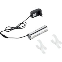
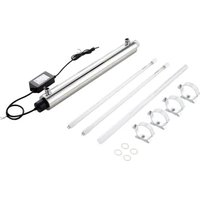
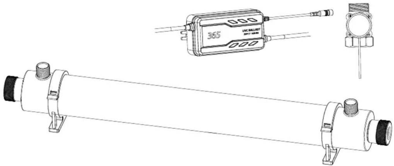
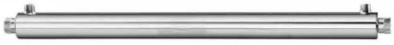
PARTS LIST
 | x1 | 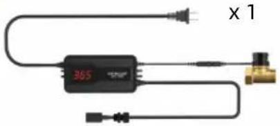 | |
x 2(One more) 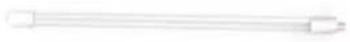 |  | x1 | x4(Two more) 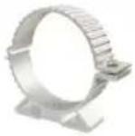 |
x 4 (Two more)  |  | x2 | x1  |
INSTALLATION
Open package to check all components inside:
Reactor Chamber, UV Lamp, Quartz Tube, O-rings, Electronic Ballast
Make sure the Quartz Tube and UV Lamp are clean before installation (clean with alcohol or mild detergent). Wear soft non-abrasive gloves to keep any finger marks away from them.
natural_image
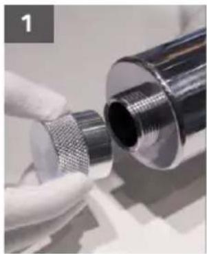
Close-up of a gloved hand holding a metallic cylindrical component with a mesh-like texture, no visible text or symbols.Remove the closed end nut from reactor chamber closed end.
natural_image
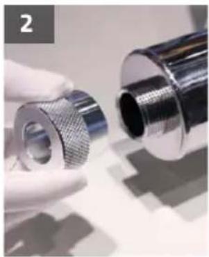
Close-up of a hand holding a metallic mechanical component, no visible text or symbolsRemove the closed end nut from reactor chamber closed end.
natural_image
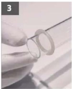
Close-up of a gloved hand holding a transparent cylindrical object, possibly a ring or film, with no visible text or symbols.Install o-ring onto the open end of quartz tube (-12mm from the edge).
natural_image
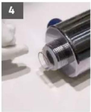
Close-up of a metallic cylindrical tube with a blue cap, partially covered by white plastic film (no visible text or symbols)Insert the quartz tube into the reactor chamber.
natural_image
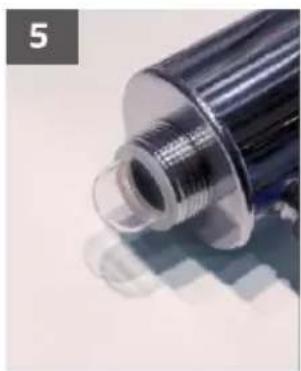
Close-up of a metallic cylindrical object with a threaded end and reflective surface (no visible text or symbols)Install o-ring onto the closed end of quartz tube.
natural_image
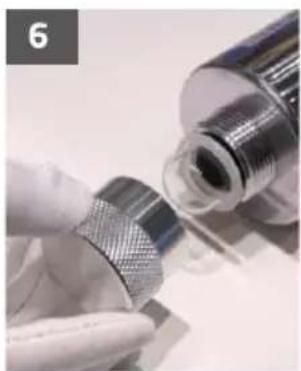
Close-up of a gloved hand holding a metallic mechanical component with a small inset showing internal structure (no visible text or symbols)Hand-screw closed end nut on the reactor chamber (closed end of quartztube) to protect the o-ring, do not over tighten.
natural_image
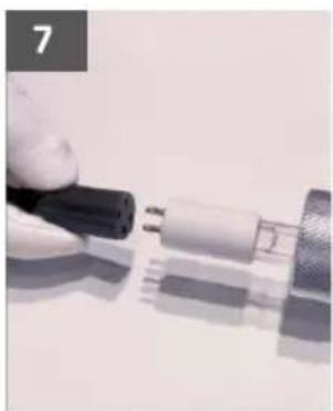
Close-up of a hand holding a black connector next to a white cable or connector (no visible text or symbols)Connect the lamp socketwith uv lamp pins tightly.
natural_image
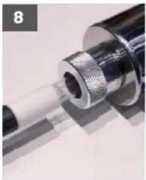
Close-up of a metallic mechanical component with threaded end and cylindrical shaft (no visible text or symbols)Carefully insert the UV lamp into the quartz tube through open end nut.
natural_image
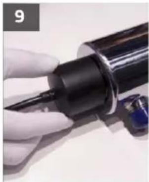
Close-up of a hand holding a black cylindrical object with a blue clip, no visible text or symbolsInstall the cover cap and hand-tighten onto open end nut.
natural_image
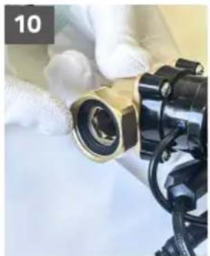
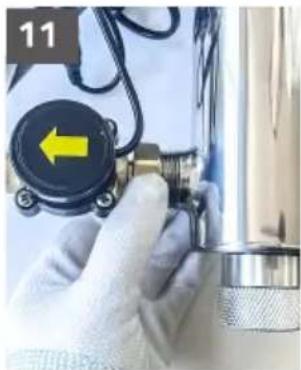
Close-up of gloved hands holding a mechanical component, no visible text or symbolsTake out a sealing ring and install it at the connection between the brass water flow switch and the water outlet of the UV tube body.
natural_image
Close-up of a gloved hand holding a small mechanical component with a yellow arrow pointing left, next to a metallic cylindrical device (no visible text or symbols)Clockwise tightening
12
Select a readily accessible and well lit location to fix the system. The system should always be located closest to the point of use and can either be installed horizontally or vertically.
13
When all plumbing connections are finished, slowly turn on the water supply and check for leaks.
14
Allow the water to run for a few minutes to clear any air or dust that may be in the Reactor Chamber. Connect the power for starting up.
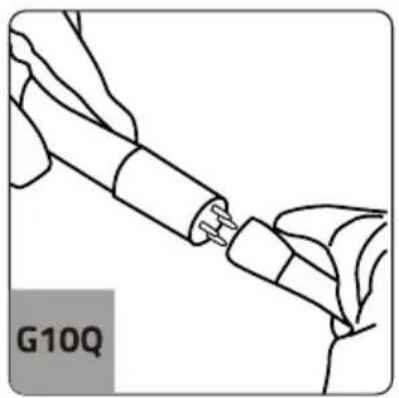
LAMP CONNECTION
Connect the lamp socket of the ballast output line to the four-pin of the lamp. The interface between the G10Q lamp socket and the lamp connector a foolproof connection way. Pay attention to the hole distance and align it so that it can be inserted. Or the lamp holder rotates 90 degrees. When connecting the lamp to the lamp socket, hold the ceramic lamp connector part of the lamp with your hand, and do not touch the glass of the lamp to prevent it from breaking.
natural_image
Line drawing of a hand holding a connector or cable, with no visible text or symbols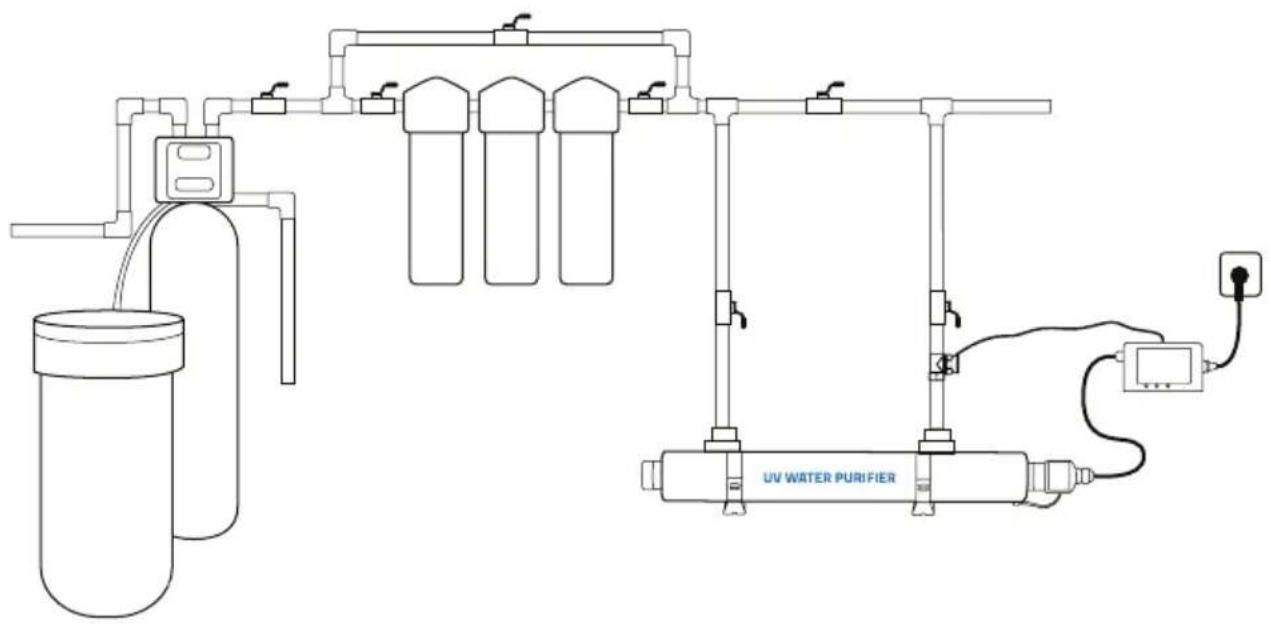
BALLAST TIMER SETTING
Timing time adjustment:
Press the button in the standby state digit starts to flash, and then press the button to set up the numbers 0-9, and so on. After the 3 digits are adjusted, there is no longer flash and the adjustment is complete. Users can adjust the timing time according to the needs.
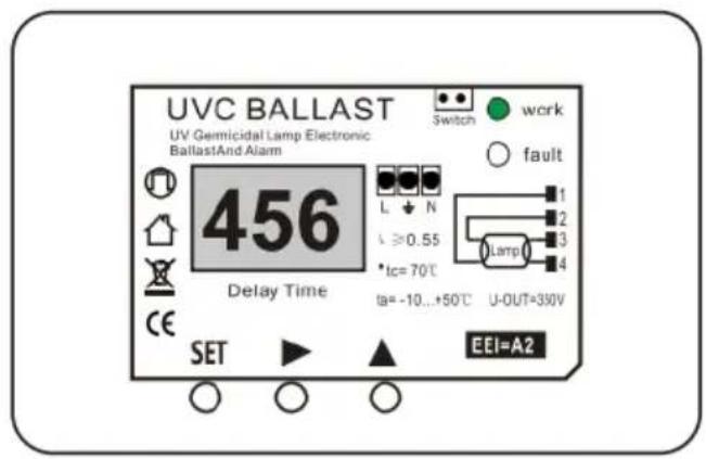
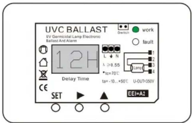
Automatic start time adjustment:
Press the SET button first, the display panel appears with "H", and H stands for hour, and then set the andfor time setting of automatically start, the method is the same as setting the timer time, but the number of becomes two digits, and the maximum can be set to 99 hours.
TROUBLESHOOTING
| Symptom | Possible Causes | Solutions |
| High Bacteria Counts | Quartz Sleeve is stained or dirty. | Clean the quartz sleeve and eliminate source of staining problem. |
| Change in feed water quality. | Have source water tested to ensure that water quality is still within allowable limits for UV system. | |
| Contamination in waterafter UV system. | It is imperative that effluent water stream be shocked with chlorine (bleach) before water leaves UV system purification system must have a bacterial free distribution system to work effectively. | |
| Heated Product Water | Common problem caused by infrequent use of water. | Run water until it returns to ambient temperature. |
| Water Appears Milky | Caused by air in the water lines. | Run water until air is purged. |
| Unit Leaking Water | Problem with o-ring seal. | Ensure o-ring and washer is in place.Clean them then re-install,replace them if necessary. |
| Condensation on reactorchamber caused by excessivehumidity & coldwater. | Check location of disinfection system and control humidity. | |
| Inadequate inlet/outlet ports connections. | Check thread connections.reseal with Teflon tape and re-tighten. | |
| System Shutting Down intermittently | Interrupted power supply | Ensure system has been installed on its own circuit,as other equipment may be drawing power away from UV(ie.Pump or fridge) |
| UVsystem should not be installed on acircuit which is incorporated into a light switch | ||
| Lamp Failure Alarm on-New Lamp | Loose connection between lamp base and socket | Disconnect lamp from socket and reconnect, ensuring that tight fitis accomplished |
| Moisture build up in connector may keep lamp and socket form making a solid connection | Eliminate chance of any moisture getting to the socketand/or lamp pins |
GUIDELINES
Additional Guidelines
- Recheck the installation before plug the uv water purifier into power.
- Do not proceed to install the equipment when UV Lamp or Sleeve Tube is broken, buy one again and continue.
- UV water purifier System is designed for continuous operation and frequent switching will reduce Ultraviolet radiation and service life.
- If this unit falls into the water, turn main power off and then retrieve it. Do not attempt to use this system if it has been submerged.
- Do not operate this unit if it has a damaged cord or plug, if it is malfunctioning or if it has been dropped or been damaged in any manner.
- The UV system should be installed after the filter on the return line.
- Always disconnect the water supply and completely drain the water purifier if it will be subjected to temperatures below freezing for extended periods of time.
Note: To save the energy, turn off the power and water supply if you do not use the equipment for a long time.
MAINTENANCE & INSPECTION
MAINTENANCE:
The water purifier is designed to operate with a minimal amount of maintenance, providing the water quality does not exceed maximum concentration levels, see "Water Quality "in the "Principle of Operation" section. Ordinary maintenance consists of:
- Lamp replacement is recommended every 8,000 hrs of operation, approximately 12 months of continuous service.
- Cleaning of the quartz sleeve, when conditions warrant. It is recommended that the inspection of quartz sleeve be performed after one month of use. If quartz sleeve is found to be coated (not clear), then frequency of cleaning must be done more often. Deposits or discoloration on the surface of quartz sleeve are caused by excessive levels of the subject contaminant within the water that is in contact with the quartz sleeve. Most often false deposits on the quartz sleeve are caused by an excess of calcium(hardness), iron or manganese.
INSPECTION:
● Regularly inspect the water purifier to ensure that the UV lamp is still in operation.
- An LED indicator light, located on the ballast, provides visual indication of UVlamp operator. This provides an indication of lamp operation and does not indicate the level of ultraviolet intensity or transmission through the water.
- Ballasts have a built-in audio alarm which will indicate lamp failure.
- To ensure proper operation of the water purifier, regular biological testing should be performed on a schedule recommended by local public health authorities, or at minimum; at installation, quarterly for the first year of service and annually, at lamp replacement, for the life of the water purifier.
- Additional testing should be performed whenever modifications, change or additions are made to plumbing system, pumps, well source water etc. to ensure adequate performance under new condition.
- As with any water purifier installation, routine maintenance is necessary to ensure your equipment is operating correctly. Regular inspection must also include the inspection of the ground to ensure grounding wires are secure to both the water purifier and grounding point as originally installed. Regular inspection must also include confirmation that approved ground fault circuit interrupt (GFCI) receptacle is still operational and that water purifier is plugged into this GFCI. Any components which are damaged, or broken should be replaced.
VEVOR®
TOUGH TOOLS, HALF PRICE
Technical Support and E-Warranty Certificate
www.vevor.com/support
VEVOR®
TOUGH TOOLS, HALF PRICE
natural_image
Technical line drawing of a cylindrical mechanical device with attached UVC ballast sensor (no text or symbols on the device itself)POTRZEBUJESZ POMOCY? SKONTAKTUJ SIĘ Z NAMII
| Maximum Concentration Levels | |
| Turbidity < 1 NTU | Manganese 0.05 mg / L |
| Total Suspended Solids 10 mg /L | pH: 6.5 - 9.5 |
| Color: None | Hardness :6 GPG or 102.6 PPM |
| Iron: 0.3 mg /L | Tannins: < 0.1 ppm (0.1 mg / L) |
natural_image
Close-up of a hand holding a metallic cylindrical object with a dark hole, no visible text or symbolsnatural_image
Close-up of two metallic mechanical components with a hand adjusting one (no visible text or symbols)natural_image
Close-up of a hand holding a small ring with a string, no visible text or symbolsnatural_image
Close-up of a metallic cylindrical object with a transparent end, possibly a pen or tool, against a blurred background (no visible text or symbols)natural_image
Close-up of a metallic cylindrical object with reflective surface, possibly a brush or tube (no visible text or symbols)natural_image
Close-up of hands using a tool to adjust a metal component (no visible text or symbols)natural_image
Close-up of a hand holding a small mechanical component (no visible text or symbols)natural_image
Close-up of a mechanical component with metallic fittings and a cylindrical shaft (no visible text or symbols)natural_image
Close-up of a hand holding a black cylindrical object with a blue clip, no visible text or symbolsnatural_image
Close-up of mechanical components with no visible text or symbolsnatural_image
Close-up of a gloved hand holding a small mechanical component with a yellow arrow pointing left (no visible text or symbols)natural_image
Line drawing of a hand connecting two plug connectors to a terminal block (no text or symbols)
USTAWIANIE TIMERA BALASTA
natural_image
Technical line drawing of a cylindrical mechanical device with attached UVC ballast sensor (no text or symbols on the device itself)| Maximum Concentration Levels | |
| Turbidity < 1 NTU | Manganese 0.05 mg / L |
| Total Suspended Solids 10 mg /L | pH: 6.5 - 9.5 |
| Color: None | Hardness :6 GPG or 102.6 PPM |
| Iron: 0.3 mg /L | Tannins: < 0.1 ppm (0.1 mg / L) |
natural_image
Close-up of a hand holding a metallic cylindrical object with a circular opening (no visible text or symbols)natural_image
Close-up of two metallic mechanical components with a hand adjusting one (no visible text or symbols)natural_image
Close-up of a hand holding a small ring, with no visible text or symbolsnatural_image
Close-up of a cylindrical mechanical component with a transparent end, possibly a tool or sensor (no visible text or symbols)natural_image
Close-up of a metallic cylindrical object with a transparent end, partially covered by a translucent surface (no visible text or symbols)natural_image
Close-up of hands using a tool to adjust a metal component (no visible text or symbols)natural_image
Close-up of a hand holding a small object with a black handle, next to a metallic cylindrical component (no visible text or symbols)natural_image
Close-up of a metallic mechanical component with threaded end and cylindrical body (no visible text or symbols)natural_image
Close-up of a hand holding a black cylindrical object with a blue clip, no visible text or symbolsnatural_image
Close-up of mechanical components with no visible text or symbolsnatural_image
Close-up of a gloved hand holding a small mechanical component with a yellow arrow pointing left (no visible text or symbols)natural_image
Line drawing of a hand connecting two plug connectors to a terminal block (no text or symbols)
Zeiteinstellung:
www.vevor.com/support
VEVOR®
TOUGH TOOLS, HALF PRICE
natural_image
Technical line drawing of a cylindrical mechanical device with attached UVC ballast sensor (no text or symbols)BESOIN D'AIDE? CONTACTEZ-NOUS!
| Maximum Concentration Levels | |
| Turbidity < 1 NTU | Manganese 0.05 mg / L |
| Total Suspended Solids 10 mg /L | pH: 6.5 - 9.5 |
| Color: None | Hardness :6 GPG or 102.6 PPM |
| Iron: 0.3 mg /L | Tannins: < 0.1 ppm (0.1 mg / L) |
natural_image
Close-up of a hand holding a metallic cylindrical object with a circular opening (no visible text or symbols)natural_image
Close-up of two metallic mechanical components with a hand adjusting one (no visible text or symbols)natural_image
Close-up of a hand holding a small ring with a string, no visible text or symbolsnatural_image
Close-up of a metallic cylindrical object with a transparent end, possibly a pen or tool, against a blurred background (no visible text or symbols)natural_image
Close-up of a metallic cylindrical object with a transparent end, partially covered by a light-colored surface (no visible text or symbols)natural_image
Close-up of hands using a tool to adjust or install a mechanical component (no visible text or symbols)natural_image
Close-up of a hand holding a small object with a black handle, next to a metallic cylindrical component (no visible text or symbols)natural_image
Close-up of a mechanical component with metallic fittings and a cylindrical shaft (no visible text or symbols)natural_image
Close-up of a hand holding a black cylindrical object with a blue clip, no visible text or symbolsnatural_image
Close-up of mechanical components with no visible text or symbolsnatural_image
Close-up of a gloved hand holding a small mechanical component with a yellow arrow pointing left (no visible text or symbols)natural_image
Line drawing of a robotic arm connecting a tool to a human arm (no text or symbols)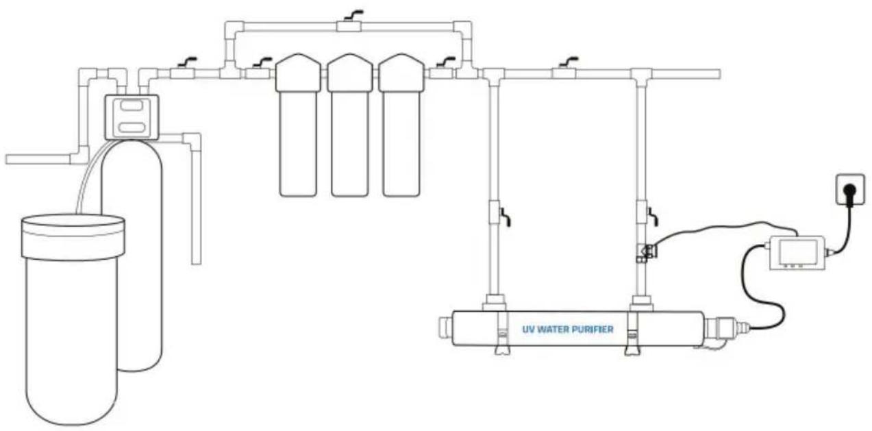
natural_image
Technical line drawing of a cylindrical mechanical device with attached UVC ballast sensor (no text or symbols)HULP NODIG? NEEM CONTACT METONS OP!
| Maximum Concentration Levels | |
| Turbidity < 1 NTU | Manganese 0.05 mg / L |
| Total Suspended Solids 10 mg /L | pH: 6.5 - 9.5 |
| Color: None | Hardness :6 GPG or 102.6 PPM |
| Iron: 0.3 mg /L | Tannins: < 0.1 ppm (0.1 mg / L) |
natural_image
Close-up of a hand holding a metallic cylindrical object with a dark hole, no visible text or symbolsnatural_image
Close-up of two metallic mechanical components with a hand adjusting them, no visible text or symbolsnatural_image
Close-up of a hand holding a small ring with a string, no visible text or symbolsnatural_image
Close-up of a metallic cylindrical object with a transparent end, possibly a pen or tool, against a blurred background (no visible text or symbols)natural_image
Close-up of a metallic cylindrical object with reflective surface, possibly a brush or tube (no visible text or symbols)natural_image
Close-up of hands using a tool to adjust a metal component (no visible text or symbols)natural_image
Close-up of a hand holding a small mechanical component, possibly a tool or tool, with no visible text or symbols.natural_image
Close-up of a metallic mechanical component with threaded end and cylindrical body (no visible text or symbols)natural_image
Close-up of a hand holding a black cylindrical object with a blue clip, no visible text or symbolsnatural_image
Close-up of mechanical components with no visible text or symbolsnatural_image
Close-up of a gloved hand holding a small mechanical component with a yellow arrow pointing left (no visible text or symbols)natural_image
Line drawing of a hand connecting two USB cable connectors to a terminal (no text or symbols)
BALLASTTIMER INSTELLING
natural_image
Technical line drawing of a cylindrical mechanical device with attached UVC ballast sensor (no text or symbols on the device itself)BEHÖVER HJÄLP? KONTAKTA OSS!
| Maximum Concentration Levels | |
| Turbidity < 1 NTU | Manganese 0.05 mg / L |
| Total Suspended Solids 10 mg /L | pH: 6.5 - 9.5 |
| Color: None | Hardness :6 GPG or 102.6 PPM |
| Iron: 0.3 mg /L | Tannins: < 0.1 ppm (0.1 mg / L) |
natural_image
Close-up of a hand holding a metallic cylindrical object with a circular opening (no visible text or symbols)natural_image
Close-up of two metallic mechanical components with a hand adjusting one (no visible text or symbols)natural_image
Close-up of a hand holding a small ring or wire, with no visible text or symbolsnatural_image
Close-up of a metallic cylindrical object with a transparent end, possibly a pen or tool, against a blurred background (no visible text or symbols)natural_image
Close-up of a metallic cylindrical object with a transparent end, partially covered by a light-colored surface (no visible text or symbols)natural_image
Close-up of a gloved hand holding a small mechanical component, possibly a tool or device (no visible text or symbols)natural_image
Close-up of a hand holding a pen, partially visible against a plain background (no text or symbols)natural_image
Close-up of a mechanical component with threaded end and shaft (no visible text or symbols)natural_image
Close-up of a hand holding a black cylindrical object with a pen tip, no visible text or symbolsnatural_image
Close-up of mechanical components with no visible text or symbolsnatural_image
Close-up of a gloved hand holding a small mechanical component with a yellow arrow pointing left (no visible text or symbols)12
natural_image
Line drawing of a hand connecting two plug connectors to a terminal block (no text or symbols)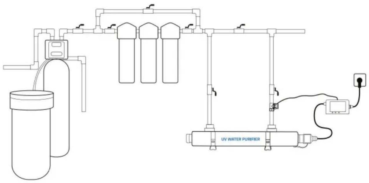
www.vevor.com/support
VEVOR®
TOUGH TOOLS, HALF PRICE
natural_image
Technical line drawing of a cylindrical mechanical device with attached UVC ballast sensor (no text or symbols on the device itself)| Maximum Concentration Levels | |
| Turbidity < 1 NTU | Manganese 0.05 mg / L |
| Total Suspended Solids 10 mg /L | pH: 6.5 - 9.5 |
| Color: None | Hardness :6 GPG or 102.6 PPM |
| Iron: 0.3 mg /L | Tannins: < 0.1 ppm (0.1 mg / L) |
natural_image
Close-up of a hand holding a metallic cylindrical object with a circular hole, no visible text or symbolsnatural_image
Close-up of two metallic mechanical components with a hand adjusting them, no visible text or symbolsnatural_image
Close-up of a hand holding a small, ring-like object with a thin wire extending from it (no visible text or symbols)natural_image
Close-up of a metallic cylindrical object with a transparent end, possibly a pen or tool, against a blurred background (no visible text or symbols)natural_image
Close-up of a metallic cylindrical object with a flanged end, partially covered by a transparent surface (no visible text or symbols)natural_image
Close-up of hands using a tool to adjust a metal component (no visible text or symbols)natural_image
Close-up of a hand holding a pen, partially visible against a plain background (no text or symbols)natural_image
Close-up of a mechanical component with metallic fittings and a cylindrical shaft (no visible text or symbols)natural_image
Close-up of a hand holding a black cylindrical object with a blue clip, no visible text or symbolsnatural_image
Close-up of mechanical components with no visible text or symbolsnatural_image
Close-up of a gloved hand holding a small electronic device with a yellow arrow pointing left, next to a metallic component (no visible text or symbols)natural_image
Line drawing of a robotic arm connecting a tool to a human arm (no text or symbols)
natural_image
Technical line drawing of a cylindrical mechanical device with attached UVC ballast sensor (no text or symbols on the device itself)| Maximum Concentration Levels | |
| Turbidity < 1 NTU | Manganese 0.05 mg / L |
| Total Suspended Solids 10 mg /L | pH: 6.5 - 9.5 |
| Color: None | Hardness :6 GPG or 102.6 PPM |
| Iron: 0.3 mg /L | Tannins: < 0.1 ppm (0.1 mg / L) |
natural_image
Close-up of a hand holding a metallic cylindrical object with a circular opening (no visible text or symbols)natural_image
Close-up of two metallic mechanical components with a hand adjusting one (no visible text or symbols)natural_image
Close-up of a hand holding a small ring or wire, with no visible text or symbolsnatural_image
Close-up of a metallic cylindrical object with a transparent end, possibly a pen or tool, against a blurred background (no visible text or symbols)natural_image
Close-up of a metallic cylindrical object with a flanged end, possibly a mechanical component or tool (no visible text or symbols)natural_image
Close-up of hands using a tool to adjust or install a mechanical component (no visible text or symbols)natural_image
Close-up of a hand holding a small mechanical component, possibly a tool or tool, with no visible text or symbols.natural_image
Close-up of a mechanical component with metallic fittings and a cylindrical shaft (no visible text or symbols)natural_image
Close-up of a hand holding a black cylindrical object with a blue clip, no visible text or symbolsnatural_image
Close-up of mechanical components with no visible text or symbolsnatural_image
Close-up of a gloved hand holding a small electronic device with a yellow arrow pointing left, next to a metallic component (no visible text or symbols)natural_image
Line drawing of a hand connecting two USB cable pins to a terminal block (no text or symbols)