QXB-6 - Pressure washer Vevor - Free user manual and instructions
Find the device manual for free QXB-6 Vevor in PDF.

| Product Type | High pressure piston pump |
| Brand | Vevor |
| Model | QXB-6 |
| Maximum working pressure | 4600 PSI (approx. 317 bar) |
| Gun shut-off pressure | 5500 PSI (approx. 379 bar) |
| Factory set pressure | 3800 PSI (approx. 262 bar) |
| Maximum flow | 4.4 GPM (approx. 16.7 L/min) |
| Corresponding power | 13-15 HP (approx. 9.7-11.2 kW) |
| Adaptive model (engine displacement) | 420-460 cc |
| Drive type | Belt, flexible coupling or direct flange |
| Number of pistons | 3 (triple piston) |
| Lubrication | Oil (see lubricant table in the manual) |
| Oil change | First oil change at 50 h, then every 500 h or 1 year |
| Recommended intake filtration | 50-80 mesh, capacity double the rated flow |
| Maximum intake vacuum | 0.25 bar (measured at pump intake) |
| Operating ambient temperature | 10 to 35 °C |
| Maximum relative humidity | 80% |
| Intended use | Industrial high pressure cleaners (washing of raw materials, finished products) |
| Pump body material | Cast iron or aluminum alloy (not explicitly specified) |
| Safety valve | Integrated adjustable relief (bypass) valve |
| Supplied accessories | Temporary oil cap, breather cap, sealing plugs |
| Compatible models | QXB-4, QXB-5, QXB-6, QXB-7, QXB-8, QXB-9, GYB-3, GYB-4 |
| Technical support and warranty | www.vevor.com/support |
| Manufacturer | Shanghai Muxin Muye Youxiangongsi, Shanghai, China |
| Importer (EU) | E-CrossStu GmbH, Frankfurt am Main, Germany |
Frequently Asked Questions - QXB-6 Vevor
User questions about QXB-6 Vevor
0 question about this device. Answer the ones you know or ask your own.
Ask a new question about this device
Download the instructions for your Pressure washer in PDF format for free! Find your manual QXB-6 - Vevor and take your electronic device back in hand. On this page are published all the documents necessary for the use of your device. QXB-6 by Vevor.
USER MANUAL QXB-6 Vevor
Technical Support and E-Warranty Certificate
www.vevor.com/support
PRESSURE WASHER PUMP
MODEL:QXB-4/QXB-5/QXB-6/QXB-7/QXB-8/QXB-9/GYB-3/GYB-4
We continue to be committed to provide you tools with competitive price. "Save Half", "Half Price" or any other similar expressions used by us only represent of savings you might benefit from buying certain tools with us compared to top brands and does not necessarily mean to cover all categories of tools offered are kindly reminded to verify carefully when you are placing an order with us actually saving half in comparison with the top major brands.
VEVOR®
TOUGH TOOLS, HALF PRICE
PRESSURE WASHER PUMF
natural_image
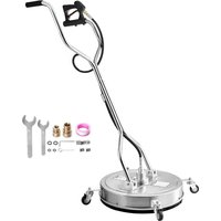
Technical line drawing of a mechanical assembly with no visible text or symbolsQXB-4/GYB-3
natural_image
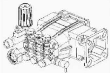
Technical line drawing of a mechanical device with multiple gears and a central hub (no text or symbols)QXB-5/GYB-4
natural_image
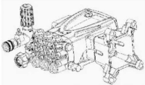
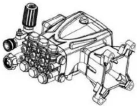
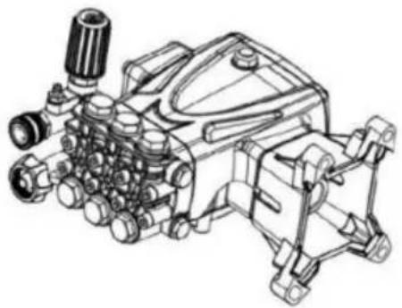
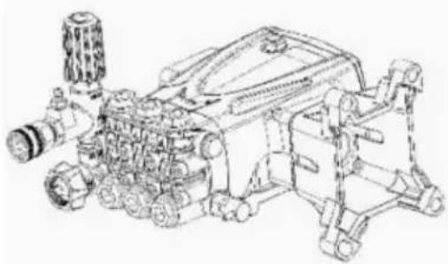
Technical line drawing of an internal combustion engine assembly (no text or labels)QXB-6/QXB-7 QXB-8/QXB-9
natural_image
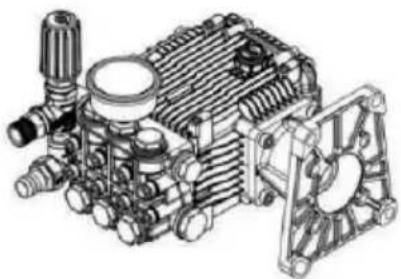
Technical line drawing of a mechanical pump assembly (no text or labels)NEED HELP? CONTACT US!
Have product questions? Need technical support? Please feel fr contact us:
Technical Support and E-Warranty Certificate www.vevor.com/support
This is the original instruction, please read all manual instruction carefully before operating. VEVOR reserves a clear interpretation user manual. The appearance of the product shall be subject to product you received. Please forgive us that we won't inform you there are any technology or software updates on our product.
GENERAL INEORMATLON
Purpose of the manual
The manufacturer has provided this manual to provide the operating instructions and the criteria to be complied with when installing, using a maintaining the pump identified by the designation on the cover.
The manufacturer supplies the original instructions in the English language.
The manufacturer may supply the original instructions in other language in response to statutory or commercial requirements.
If the pump is sold, the seller must pass on this manual to the new along with the appliance.
The instructions are intended for the skilled, suitably trained operators v carry out the installation and routine maintenance procedures.
Refer to the table of contents for rapid access to the topics covered. The manufacturer reserves the right to amend the manual without not unless the amendments refer to the pump's level of safety.
The purchaser must ensure that the installation is designed in accordance with the instructions in this manual, statutory requirements, and the relevant national and local regulations.
The technical instructions in this"Use and Installation Manual"are the property of the manufacturer and must be treated as confidential.
There may be differences between the illustrations and the pump's ac conformation, but any such differences will not affect the clarity of the instructions. If in doubt, request the necessary explanations from the manufacturer.
The symbols shown and described below are used to identify safety or important information.
Danger-Warning
Identifies information or procedures the failure to comply with which m constitute a serious threat to health and safety.
Caution
Identifies information or procedures the failure to comply with which m constitute a threat to health and safety or cause damage.
Information
Identifies useful and important information or procedures that should be borne in mind.
Pump and manufacturer identification
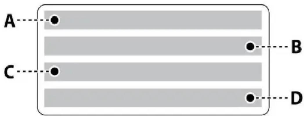
Data plate
The data plate shown here, containing essential information for safe operation, is affixed to every pump.
A)L/min/GPM
B)MPa/psi
C)RPM
D)Kw
GENERAL INEORMATION
After-Sales service procedures
To request after-sales service(in the event of a pump malfunction or failure,etc.), contact your nearest service centre or the manufacturer.
When requesting after-sales services, always state the pump's data plate data and the type of problem.
Disclaimer
The manufacturer accepts no liability arising from:
- Incorrect installation;
- Improper use of the pump;
- Failure to service the pump;
- Unauthorized modifications and/or repairs;
- Use of non-original spare parts, or parts not specifically intended the model.
Annexed documentation
The following documentation is issued to the Customer together with 1 manual:
- Declaration of incorporation
Glossary
Purchaser: Individual, organization or company which has purchased the pump and intends to use it for the intended purposes.
Routine maintenance: All operations required to keep the pump in good working order to ensure a longer working life and maintain compliance safety requirements. The manufacturer describes the maintenance procedures and intervals in this "Use and Installation Manual".
Repairs: All operations performed to conserve the pump's efficiency and operating characteristics. These procedures, required in the event of an unexpected malfunction, must only be carried out by a skilled technician. The information for the use of skilled repair technicians only is provided the "Repairs Manual".
Operator: An authorized person having the prerequisites, skills and information needed for the use of the pump or the machine or plant which the pump is installed, and for routine maintenance procedures.
Installer: Authorized technician having the prerequisites and the specific skills required for the tasks involved in the installation of the pump as similar machinery and for the performance of the routine maintenance operations in conditions of safety, independently and without risk.
Training: A phase necessary to transfer to the operators the knowled needed for the correct, risk-free performance of operations.
TECHNICAL INEORMATION
General description
The pump is designed and constructed to pump and compress liquids high pressure in industrial applications. The pumping action is provided a series of pistons connected to the drive shaft by connecting-rods.
When in operation, the pistons perform an axial stroke inside the head where the intake and delivery ducts are fitted with valves that allow liquid to pass in one direction only.
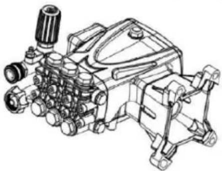
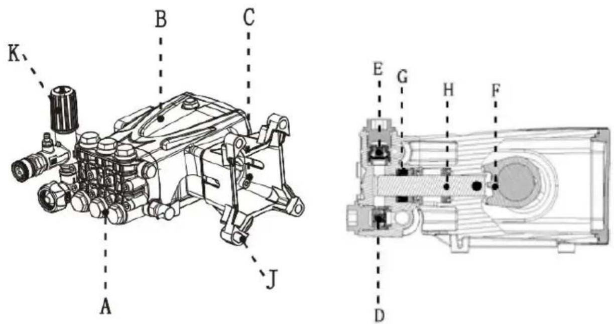
Main components
The pump is designed and built for incorporation in machinery and plants(machinery for washing raw materials, finished products, etc.).
The pump must be used in a manner appropriate to its technical data(see"Technical Data"), and must not be modified or improperly used
Misuses
Do not put the pump into service until the plant or machinery in which incorporated has been declared compliant with the relevant national and local legal requirements.
Do not use the pump in a potentially explosive atmosphere.
Do not use the pump for flammable, toxic or corrosive liquids, or those unsuitable density. Do not take in liquids at temperatures higher than t specified in the technical data.
Do not use the pump for the supply of drinking water.
Do not use the pump on products for human consumption.
Do not use the pump on pharmaceutical products.
Residual risks
Even if the safety regulations and information provided in the manual complied with, the residual risk described below is still present during the use of the pump.
- Thermal hazard: Depending on the temperature of the liquid pump, pump may reach high temperatures when in operation. The designer of installation must therefore bear this in mind and provide the appropria measures and warning signs for staff.
TECHNICAL INEORMATION
Technical Data
The technical and performance data are stated on the cover.
The pump's intake circuit must include a filter having a capacity at le twice the pump's delivery rate, which must not cause restrictions or h losses. The recommended degree of filtration is 50-80 mesh.Maximum intake vacuum-0.25 bar, measured at the pump intake.
Overall dimensions
The illustrations showing the overall dimensions are provided in the annexes.
Environmental operating limits
The pump operates correctly at an ambient temperature between 10 a 35°C, with a relative humidity of 80%.
| Product Specifications and Packing Lis | ||||
| Model | QXB-4 | QXB-5 | QXB-6 | QXB-7 |
| Working Pressure | 2600 PSI | 4500 PSI | 4600PSI | 4600PSI |
| Gun Closing Pressure | 3800 PSI | 5200 PSI | 5500PSI | 5500PSI |
| Factory set pressure | 2500 PSI | 3600 PSI | 3800 PSI | 3700PSI |
| Matching Horsepower | 6.5-7/HP | 13-15/HP | 13-15/HP | 13-15/HP |
| Maximum Flow | 2.5 GPM | 4.2 GPM | 4.4 GPM | 4.4 GPM |
| Adaptive Model | 208~230CC | 420~460cc | 420~460cc | 420~460cc |
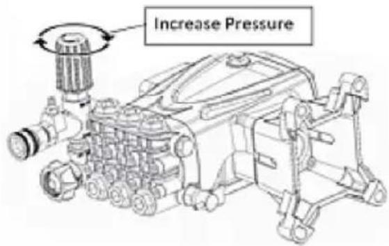
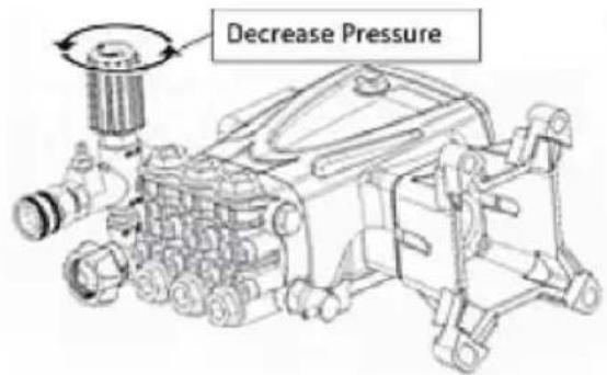
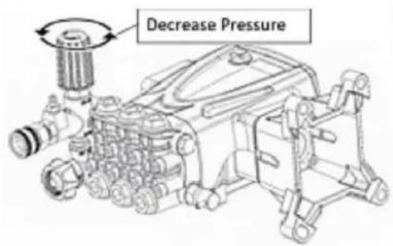
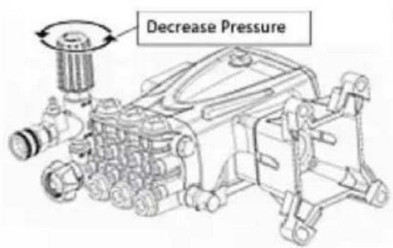
Note: To match engines with different power, the factory set pressure will less than the rated maximum pressure. Just adjust the pressure limiting valve if you need to increase the pressure.
SAFETY INEORMATION
General safety rules
Most workplace accidents and injuries are caused by carelessness and failure to comply with common sense and safety rules.
In most cases, accidents can be avoided by predicting their possible causes and proceeding with the necessary care and attention.
A careful operator who follows the rules is the best guarantee agains accidents.
Before installing and using the pump, the operators and other staff must read and understand the instructions in the manual provided and the details of the installation design.
Do not tamper with, disarm or bypass the safety devices as this may serious threats to health and safety. Do not release pollutants into the environment.
Dispose of waste in accordance with statutory requirements.
Before performing any procedure, adopt appropriate safety measures in accordance with the relevant statutory occupational safety requirements and comply with the safety regulations in the manual.
Safety recommendations for handling and lifting
Before starting the operations, organize the intended working area so that the materials can be lifted and handled in safety.
Unloading, loading, handling and lifting operations must be carried out by skilled, authorized, and specifically trained staff.
During lifting and handling operations, the people not involved in the operations must remain at a safe distance.
For lifting, use hooks and ropes that are free from damage and appropriate for the load to be lifted.
Packaging description and unpacking
The packaging normally consists of a cardboard box for easy, safe transport.
Depending on the quantity of goods to be shipped and the place of destinat packages may be fixed on a pallet for easier lifting and handling.
Check the weight of the item on the transport documents to allow the use of suitable lifting equipment.
When unpacking, check that all components are present and intact. If items are missing or damaged, contact the dealer or manufacturer to agree on the procedures to be followed.
The packaging material must be disposed of appropriately in accordance with relevant statutory requirements.
Transport
The pump may be shipped by a variety of means of transport(road, rail, sea) depending on its destination. Secure the packaging firmly to the vehicle during transport to prevent random movement.
Storage
In the event of a lengthy period out of use, place the pump(in its packaging possible or otherwise protected) under cover, protected from the weather.
Do not store in places where the ambient conditions might impair the pump's operating condition over time.
INSTALLATION INSTRUCTIONS
Safety recommendations for installation
Take all possible precautions to allow the pump to be installed in a risk-free manner.
All installation phases must be taken into consideration when designing machinery or plant in which the pump is to be installed.
The design must consider all mounting points, the means of transmission of the energy sources, and the protective and safety devices required the relevant regulations to prevent the risk of injury.
Installation
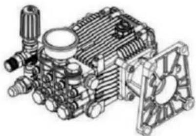
The mechanical connection between the pump and the motive power source may be made by means of a pulley and belt, or a flexible c or through a direct flanged connection to the motive power source.
The crankshaft may turn in either direction.
The water supply connection can be made equally well to the intakes the right or left of the pump(see diagram). Only connect the pump to filtered, clean water sources.
Unscrew the plugs fitted on the various ports in the factory by the manufacturer, and screw the plugs onto the ports not used, depending connection requirements.
Replace the oil plug (A), used for shipment with the breather plug (B) supplied.
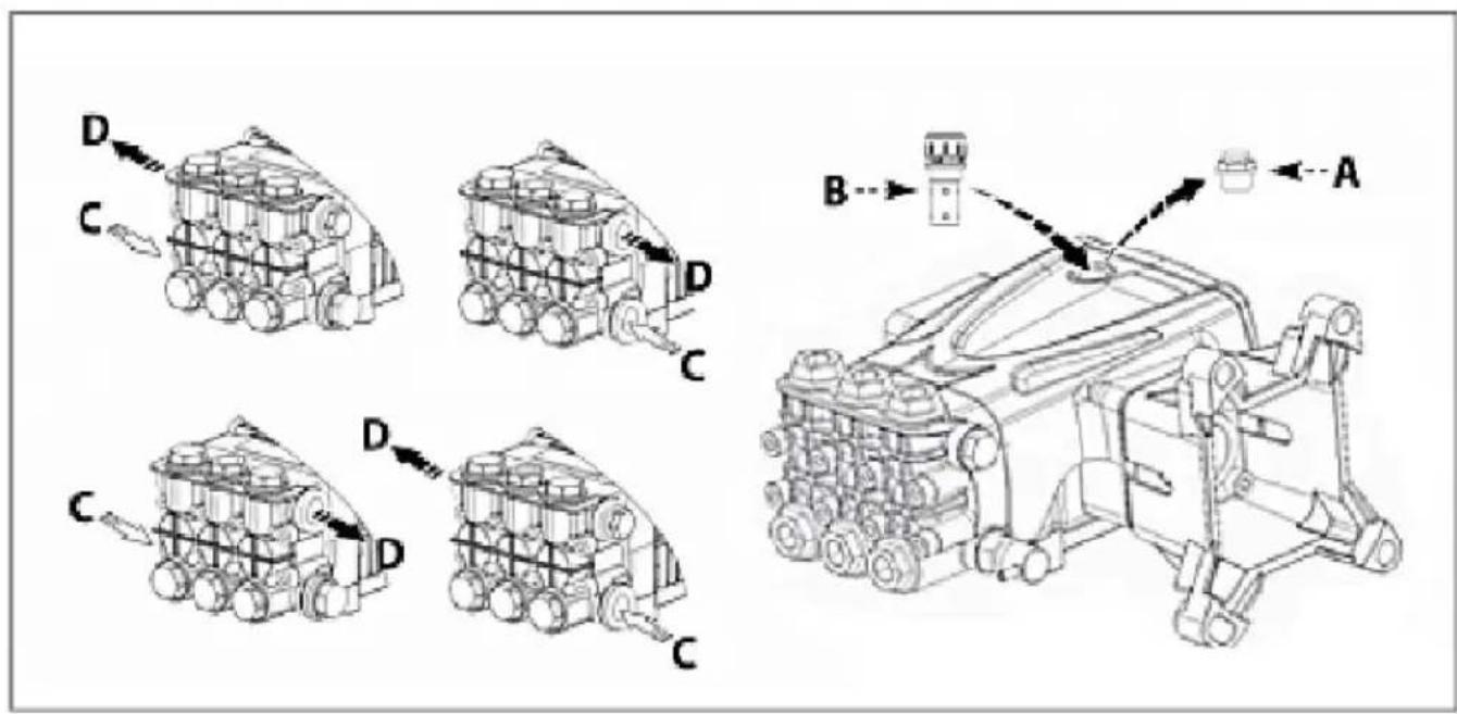
A) Temporary oil plug B) Oil plug with breather
C) Intake port D) Delivery port
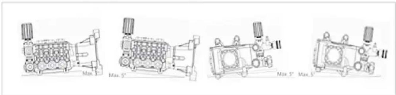
Mounting the pump
The pump must be installed on a horizontal surface with no flexible components between it and the mounting surface.
The illustration shows the maximum permitted pump installation angle beyond which proper lubrication of the crank mechanism is not ensure
Secure the pump with screws of suitable diameter and length, fixing through the holes provided in the pump body.
INSTALLATION INSTRUCTIONS
General guidelines on water supply connection
The pump's water supply connection can be made in one of the way below.
Connection to the mains water supply.
Connection to a tank(gravity-feed).
Connection to an external pump(force-feed).
The following requirements must be met for all types of connection.
1) The pump must be supplied by means of a crush-proof hose of diameter for the pump's intake connection(see "Technical Data").
2) There must be no restrictions or kinks in the hose.
3) A suitable filter must be installed at the pump intake(see "Technical Data").
4) All connections between the unions and the intake line must be s to prevent the pump from sucking in the air.
5) The connections and pipes must be suitable for the operating pres and the pump delivery rate, and must comply with the relevant regulations.
6) To ensure operating safety install a relief valve(by-pass valve) suitable for the pump's technical data and with a suitable setting downstream the pump.
7) The relief valve dump line must never be connected to the pump line.
8) Install a pressure damper downstream of the pump to minimize the water hammer effect in the delivery pipeline.
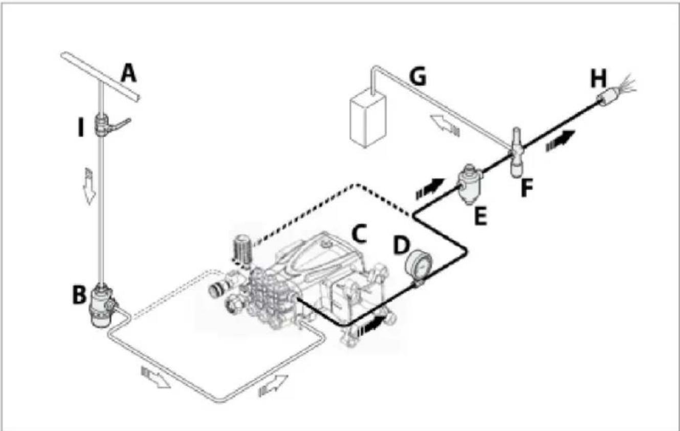
Connection to the mains water supply
The connection must comply with the recommendations provided.
1) The mains water system must have a flow rate twice the pump's delivery rate and a pressure of 2-3 bar.
2) Adopt all the precautions described in the "General Guidelines on W Connections" section.
The following is a simplified illustration of the layout for connection of pump to the mains water supply.
flowchart
graph TD
    A["A"] --> B["B"]
    B --> C["C"]
    C --> D["D"]
    D --> E["E"]
    E --> F["F"]
    F --> G["G"]
    G --> H["H"]
    style A fill:#f9f,stroke:#333
    style B fill:#f9f,stroke:#333
    style C fill:#ccf,stroke:#333
    style D fill:#ccf,stroke:#333
    style E fill:#cfc,stroke:#333
    style F fill:#fcc,stroke:#333
    style G fill:#cff,stroke:#333
    style H fill:#ffc,stroke:#333
A) Mains water supply
F) Relief valve (by-pass valve)
B) Intake filter
G) Dump pipeline
C) High pressure pump
H) Nozzle
D) Pressure gauge
I ) Shut-off valve
E) Pressure damper
INSTALLATLON INSTRUCTIONS
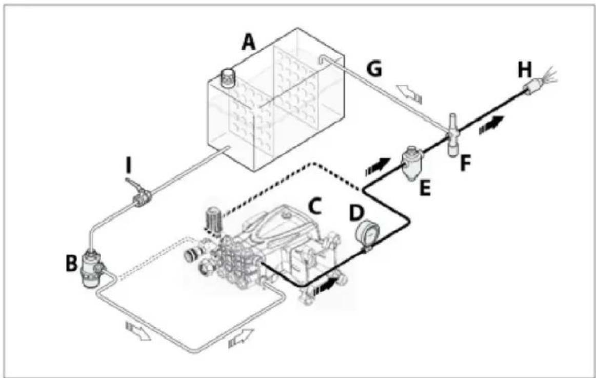
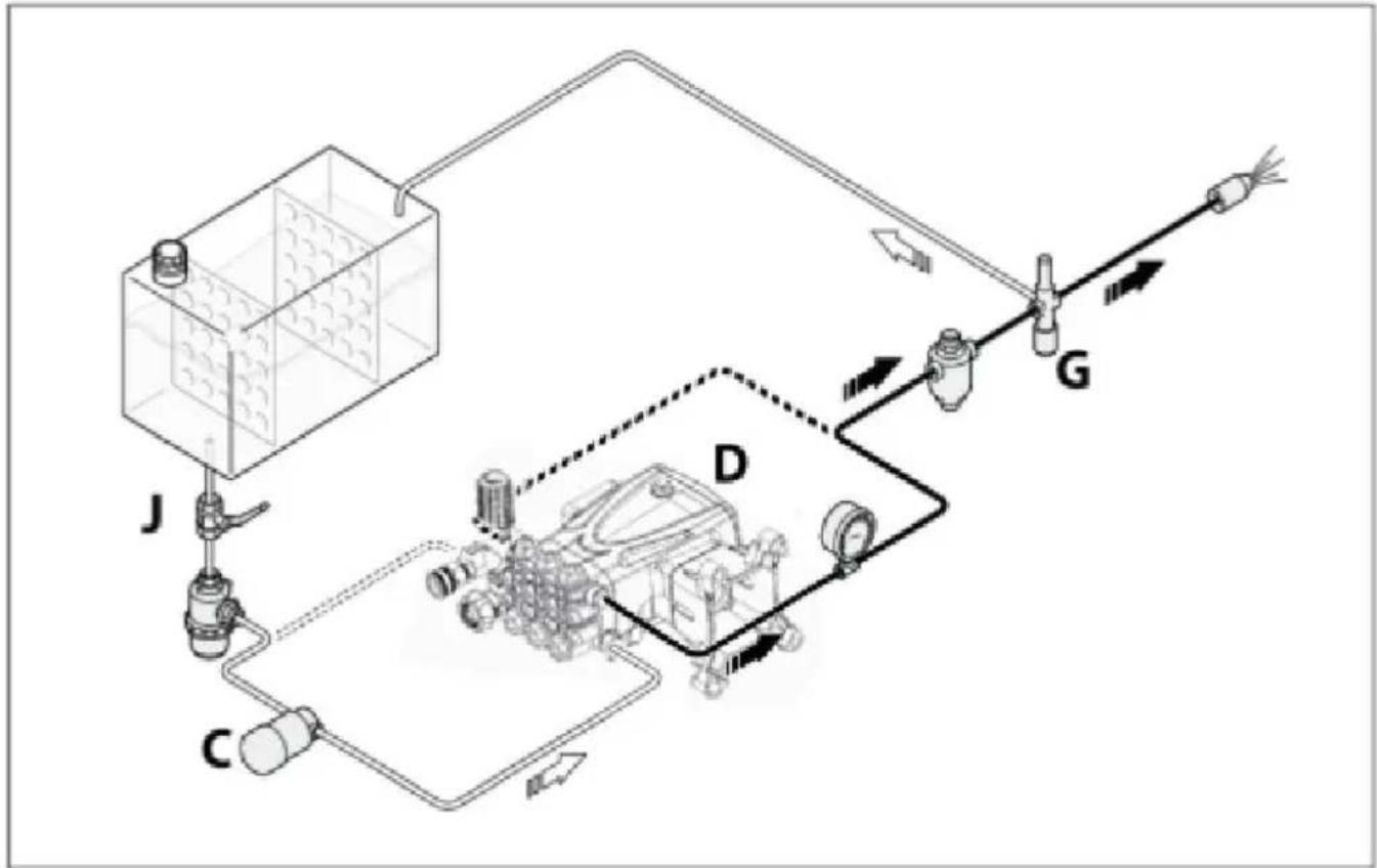
Connection to a tank(gravity-feed)
The connection must comply with the recommendations provided.
1) The pump must be installed in a position below the tank intake (positive head).
2) The tank must have baffles to prevent water splashes and its cap must be at least 10 times greater than the pump's rated displacement.
3) The vacuum measured directly at the pump intake port must not be above 30^ C . 0.1 bar and the water temperature must not be above 30^ C .
4) Adopt all the precautions described in the "General Guidelines on W Connections" section. The following is a simplified illustration of the layout for the connection of the pump to a tank.
flowchart
graph TD
    A[" tank A "] -->|G| B[" Processing Unit B "]
    A -->|I| C[" Processing Unit C "]
    A -->|D| D[" Processing Unit D "]
    A -->|E| E[" Processing Unit E "]
    A -->|F| F[" Processing Unit F "]
    F --> H[" Output H "]
    style A fill:#f9f,stroke:#333
    style B fill:#ccf,stroke:#333
    style C fill:#cfc,stroke:#333
    style D fill:#fcc,stroke:#333
    style E fill:#cff,stroke:#333
    style F fill:#ffc,stroke:#333
    style G fill:#cfc,stroke:#333
    style H fill:#fcc,stroke:#333
A) Tank
B) Intake filter
C) High pressure pump
D) Pressure gauge
E) Pressure damper
F) Relief valve(by-pass valve)
G) Dump pipeline
H) Nozzle
I) Shut-off valve
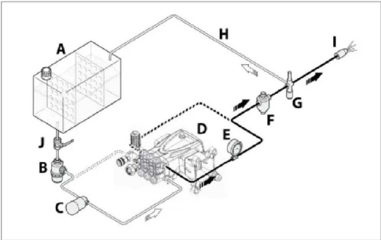
Connection to an auxiliary pump (force-feed)
The connection must comply with the recommendations provided.
1) The auxiliary pump must have a flow rate twice the high pressure pump's rated delivery rate and an operating pressure of 2-3 bar.
2) Adopt all the precautions described in the "General Guidelines on \ Connections" section.
The following is a simplified illustration of the layout for connection of pump to an auxiliary pump.
flowchart
graph TD
    A["Component A"] --> H["H"]
    H --> I["I"]
    H --> G["G"]
    G --> F["F"]
    F --> E["E"]
    E --> D["D"]
    D --> C["C"]
    C --> B["B"]
    B --> J["J"]
    style A fill:#f9f,stroke:#333
    style I fill:#ccf,stroke:#333
    style J fill:#cfc,stroke:#333
A) Tank
B) Intake filter
C) Auxiliary pump
D) High pressure pump
E) Pressure gauge
F) Pressure damper
G) Relief valve (by-pass valve)
H) Dump pipeline
I) Nozzle
J) Shut-off valve
Safety recommendations for use
Before start-up, the operator must perform the necessary safety checks.
In the event of leaks from the pressurized pipes, stop the pump a once and remove the cause of the leak. Do not operate the pump above the limits set by the manufacturer to increase its performance. If the system is to be shut down with ambient temperatures close 0°C, run the pump without water for 10 seconds with the end of delivery pipeline open to empty the system and pump of water a prevent ice from forming.
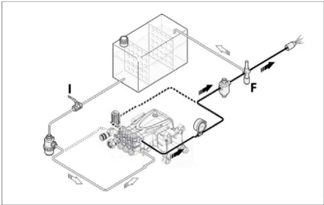
Starting and stopping the pump when supplied by the mains water system
flowchart
graph TD
    A["Input Line I"] --> B["Pump"]
    B --> C["Valve"]
    C --> D["Control Unit F"]
    D --> E["Output Line"]
    style A fill:#f9f,stroke:#333
    style E fill:#bbf,stroke:#333
To start the pump, proceed as described below.
1) Open the shut-off valve (I).
2) Open the by-pass valve (F) to depressurize the delivery pipeline.
3) Start the pump and run it for a few minutes with no pressure.
4) Adjust the by-pass valve (F) to obtain the pump's operating pressure
To stop the pump, proceed as described below.
1) Open the by-pass valve (F) to discharge the pressure.
2) Stop the pump.
3) Close the shut-off valve (I).
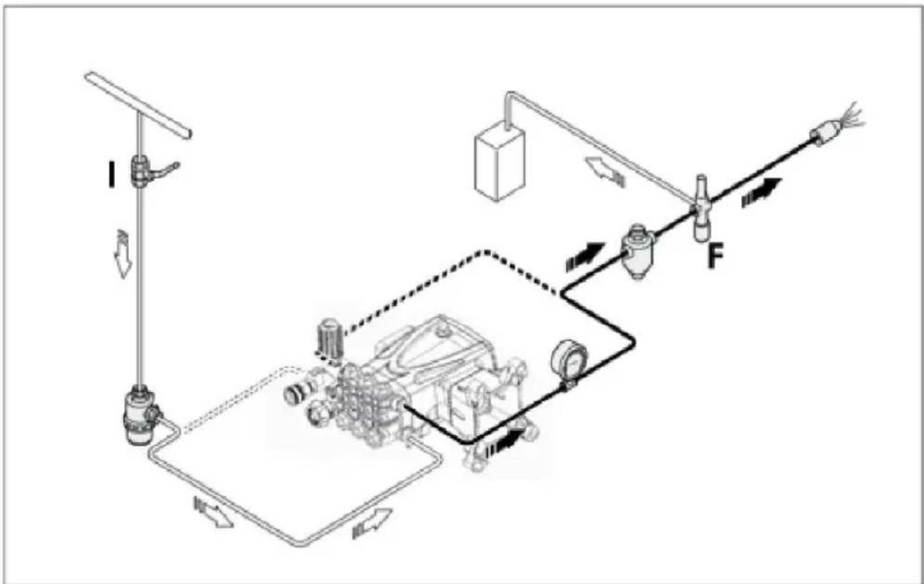
Starting and stopping the pump when supplied by gravity-feed
flowchart
graph TD
    A["Feed Pump"] --> B["Actuator"]
    B --> C["Valve"]
    C --> D["Engine"]
    D --> E["Output"]
    style A fill:#f9f,stroke:#333
    style E fill:#bbf,stroke:#333
To start the pump, proceed as described below.
1) Open the shut-off valve (I).
2) Open the by-pass valve (F) to depressurise the delivery pipeline.
3) Start the pump and run it for a few minutes with no pressure.
4) Adjust the by-pass valve (F) to obtain the pump's operating pressure
To stop the pump, proceed as described below.
1) Open the by-pass valve (F) to discharge the pressure.
2) Stop the pump.
3) Close the shut-off valve (I).
INSTRUCTIONS FOR USE
Starting and stopping the pump when supplied by an auxiliary pu
flowchart
graph TD
    A["J"] --> B["C"]
    B --> C["D"]
    C --> D["G"]
    D --> E["Output"]
    style A fill:#f9f,stroke:#333
    style B fill:#ccf,stroke:#333
    style C fill:#cfc,stroke:#333
    style D fill:#fcc,stroke:#333
    style E fill:#ffc,stroke:#333
To start the pump, proceed as described below.
1) Open the shut-off valve (J).
2) Open the by-pass valve (G) to depressurize the delivery pipeline.
3) Start the auxiliary pump (C).
4) Start the pump (D) and run it for a few minutes with no pressure.
5) Adjust the by-pass valve (G) to obtain the pump's operating pressure. To stop the pump, proceed as described below.
1) Open the by-pass valve (G) to discharge the pressure.
2) Stop the pump (D).
3) Stop the auxiliary pump (C).
4) Close the shut-off valve (J).
MAINTENANCEIN STRUCTIONS
Safety recommendations for maintenance
Before doing any maintenance work, depressurize the water system and isolate the pump from all energy sources.
When the jobs are done, before restarting the pump, check that tools, rags or other materials have been left close to moving parts in hazardous zones.
Replace any excessively worn components with original parts and use the lubricants recommended by the manufacturer.
Dispose of the worn-out components and lubricants in accordance with the relevant statutory requirements.
Carry out the routine maintenance procedures specified by the manufacturer to keep the pump safe and performing well.
| Scheduled Service Table | |||
| Every working day | Filter | Inspect filter cartridge | See"Inspecting the filter" |
| Pump | Oil level check | See"Checking the oil level" | |
| Every 50 working hours | Connection of pump to power source (pulley,belt,coupling) | Inspection | |
| Pump | Inspect mounting | See"Inspecting the pump mounting" | |
| Pipes and connections | Inspection | See"Inspecting the connections and pipes" | |
| Pump | Oil change(1) | See"Changing the oil" | |
| Pump | Oil change | See"Changing the oil" | |
| Every 500 working hours or every year | Pump gaskets | Replacement | Contact an authorized service centre |
| Every 1000 working hours | Valves | Replacement | Contact an authorized service centre |
| Filter | Inspect filter cartridge | See"Inspecting the filter" | |
(1) This interval refers to the first oil change only
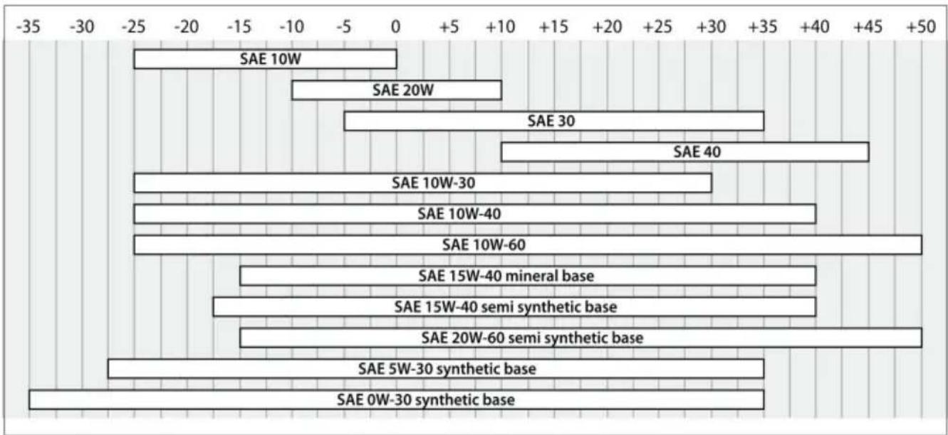
Table of lubricants
The pump is delivered complete with oil, with the characteristics stated the data plate.
When changing the oil, use an oil suitable for the conditions in the operating environment (see recommendations provided in the annexes and see "Environmental operating limits").
The correct lubricating oil viscosity depends on the external temperature. Use the graph to select the degree of viscosity best suited to the temperatures of use.
bar
| Category | Value | |---|---| | SAE 10W | -2 | | SAE 20W | -8 | | SAE 30 | -6 | | SAE 40 | -4 | | SAE 10W-30 | -10 | | SAE 10W-40 | -10 | | SAE 10W-60 | -50 | | SAE 15W-40 mineral base | -10 | | SAE 15W-40 semi synthetic base | -10 | | SAE 20W-60 semi synthetic base | -10 | | SAE 5W-30 synthetic base | -10 | | SAE 0W-30 synthetic base | -10 |MAINTENANCEIN STRUCTIONS
Inspecting the pump mounting
Check that the pump's fixing screws have not become loose.
If necessary, tighten them with the driving torque stated in the install design.
Inspecting the connections and pipes
- Inspect the connections for leaks.
Leaks can normally be dealt with by tightening the connections proper. If leaks from the intake pipeline connections are noticed, the seals m repaired.
- Inspect the hoses.
If the pipes show signs of aging, breakage, swelling, rubbing, etc., th must be replaced.
Inspecting the Filter
- Inspect the filter cartridge.
If the filter cartridge is fouled or damaged, refer to the filter manufac instructions for details on how to restore the filter cartridge to its orig filtering condition.
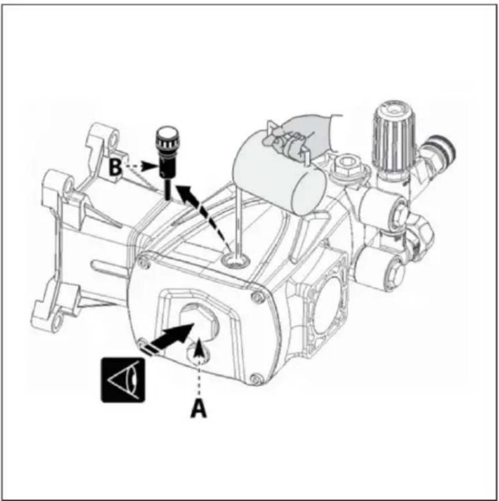
Checking the oil level
- Check the oil with the pump level and cold.
- Check the amount of oil through the level gauge (A).
- If necessary, top up with oil with the characteristics specified in the "Lubricants table".
To top up with oil proceed as described below.
1) Unscrew the plug(B) and pour oil in until it is halfway up the lev (A).
2) Screw on the plug (B).
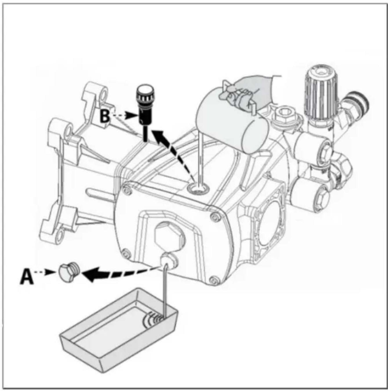
Changing the oil
Position the machine in which the pump is incorporated perfectly level, with the pump slightly warm.
Do not release oil into the environment.
Dispose of spent oil in accordance with statutory requirement
To change the oil, proceed as described below.
1) Position a receptacle of suitable capacity to collect the spent oil.
2) Unscrew the drain plug (A) and allow all the oil to flow out.
3) Screw on the drain plug( A).
4) Unscrew the filler plug (B).
5) Pour in the fresh oil through the filler hole until the correct level is reached (see "Checking the oil level").
6) Screw on the filler plug( B).
MAINTENANCEIN STRUCTIONS
Lengthy pump lay-offs
If the pump is to be unused fora long time, proceed as described b
1) Run the pump with clean water for a few minutes.
2) Operate the pump without water for 10 seconds with the end of delivery pipeline open to empty the pump and the delivery circuit a prevent scaling.
3) Flush the pump with water and solvents authorized by the relevant
4) Dry the pump with a pressurized air jet.
5) Protect the pump from the weather.
Putting the pump back into service
Before putting the pump back into service after a long period out of check the oil level and the tightness of the mounting screws.
Scrapping the pump
The pump must be scrapped by skilled staff, in compliance with the statutory requirements on occupational safety.
The dismantled components must be sorted by the type of materials which they are made. Do not dump pollutants such as seals and lub into the environment.
Dispose of them in accordance with statutory requirements with regard waste disposal and recycling.
TRQUBLE SHQOTING
The information provided is intended to provide guidance on how to get with malfunctions that may occur during use.
Some of these procedures may be carried out by skilled staff, while have to be performed at specialized service centres since they require use of specific equipment as well as detailed knowledge of repair operations.
| Problem | Cause | Remedy |
| Pump does not reach the specified pressures | Pump sucking air | Restore the tightness of the intake line |
| Intake flow rate insufficient | Increase the size of the intake pipelines | |
| Remove any kinks from the pip | ||
| Increase the filter capacity or clean the filter cartridge | ||
| Increase the rpm to the rated speed | ||
| Worn intake and delivery valves | Replace the valves (1) | |
| By-pass valve seat worn | Replace the valve | |
| Worn gaskets | Replace the gaskets(1) | |
| Unsuitable, worn nozzle | Replace nozzle | |
| Irregular variations in pressure | Worn intake and delivery valves | Replace the valves (1) |
| Valves blocked by dirt | Clean the valves(1) | |
| Air being sucked into system | Restore the tightness of the inta pipeline connections | |
| Worn gaskets | Replace the gaskets(1) | |
| Vibrations on pipes | Valves jammed | Replace the valves(1) |
| By-pass valve malfunction | Replace the by-pass valve | |
| By-pass valve dump line too small | Increase size of by-pass valve dump line | |
| Pressure damper flat | Restore pressure damper to correct inflation pressure | |
| Pump sucking air | Restore the tightness of the intake line | |
| Pressure drop | Nozzle worn | Replace nozzle |
| Worn intake and/or delivery valves | Replace the valves(1) | |
| Valves blocked by dirt | Clean the valves(1) | |
| By-pass valve seat worn | Replace the valve | |
| Worn gaskets | Replace the gaskets (1) |
(1) Operations that must be carried out at an authorized service cent
TRQUBLE SHQOTING
| Problem | Cause | Remedy |
| Pump noisy | Air being sucked into system | Restore the tightness of the intake pipeline connections |
| Intake and/or delivery valve springs broken or collapsed | Replace the valves(1) | |
| Valves blocked by di | Clean the valves(1) | |
| Worn bearings | Replace the bearings(1) | |
| Intake liquid temperature too high | Reduce liquid temperature | |
| Pump overheating | High pump operating pressure | Reduce the pressure to the rated values |
| Drive belts too taut | Restore correct belt tension | |
| Pulley or drive coupling alignment poor | Restore the correct alignment | |
| Water in oil | Guide piston gaskets worn | Replace the gaskets(1) |
| High humidity percentage in air | Change the oil twice as o (than stated in"Routine Maintenance"table) | |
| Worn gaskets | Replace the gaskets(1) | |
| Oil leaks from dump lin underneath the pump | Worn gaskets | Replace the gaskets(1) |
| Worn pistons | Replace the pistons(1) | |
| Oil leaks from dump lin underneath the pump | Guide piston gaskets worn | Replace the gaskets(1) |
(1) Operations that must be carried out at an authorized service centre
*There are any minor changes to the numbers included in the manual without prior notice.
Manufacturer: Shanghaimuxinmuyeyouxiangongsi
Address: Shuangchenglu 803nong11hao1602A-1609shi, baoshanqu, shanghai 200000 CN.
Imported to AUS: SIHAO PTY LTD, 1 ROKEVA STREETEASTWOOD NS 2122 Australia
Imported to USA: Sanven Technology Ltd., Suite 250, 9166 Anaheim Pla Rancho Cucamonga, CA 91730
| EC | REP |
E-CrossStu GmbH
Mainzer Landstr.69, 60329 Frankfurt am Ma
| UK | REP |
YH CONSULTING LIMITED.
C/O YH Consulting Limited Office 147, Centurion H London Road, Staines-upon-Thames, Surrey, TW18 4
VEVOR®
TOUGH TOOLS, HALF PRICE
Technical Support and E-Warranty Certificate www.vevor.com/support
VEVOR®
TOUGH TOOLS, HALF PRICE
natural_image
Technical line drawing of a mechanical assembly with no visible text or symbolsQXB-4/GYB-3

natural_image
Technical line drawing of a mechanical device with gears and housing (no text or symbols)QXB-5/GYB-4

natural_image
Technical illustration of an internal combustion engine assembly with no visible text or symbolsQXB-6/QXB-7 QXB-8/QXB-9
natural_image
Technical line drawing of a mechanical pump assembly (no text or labels)BESOIN D'AIDE ? CONTACTEZ-NOUS !

INFORMATIONS DE SÉCURITÉ
Changement d'huile
INSTRUCTIONS D'ENTRETIEN
A/S YH Consulting Limited Bureau 147, Centurion House,
London Road, Staines-upon-Thames, Surrey, TW18 4AX
VEVOR®
TOUGH TOOLS, HALF PRICE
www.vevor.com/support
HOCHDRUCKWASSERPUMPE
MODELL: QXB-4/QXB-5/QXB-6/QXB-7/QXB-8/QXB-9/GYB-3/GYB-4
natural_image
Technical line drawing of a mechanical valve assembly (no text or labels)QXB-4/GYB-3

natural_image
Technical line drawing of a mechanical device with gears and motors (no text or symbols)QXB-5/GYB-4

natural_image
Technical illustration of an internal combustion engine assembly with no visible text or symbolsQXB-6/QXB-7
natural_image
Technical line drawing of a mechanical pump assembly (no text or labels)QXB-8/QXB-9
| Voraus | B). Pumpenkörper | C). Kurbelwelle | D). Einlassventil |
| E). Druckventil | F). Anleitung | G). Siegel | H). Kolben |
| J) Flansch | K).Druckventil |
Anwendungsgebiete

SICHERHEITSHINWEISE
Ölwechsel
WARTUNGSANLEITUNG
C/O YH Consulting Limited, Büro 147, Centurion House, London Road, Staines-upon-Thames, Surrey, TW18 4AX
VEVOR®
TOUGH TOOLS, HALF PRICE
www.vevor.com/support
VEVOR®
TOUGH TOOLS, HALF PRICE
elettronica www.vevor.com/support
POMPA IDROPULITRICE
MODELLO:QXB-4/QXB-5/QXB-6/QXB-7/QXB-8/QXB-9/GYB-3/GYB-4
natural_image
Technical line drawing of a mechanical valve assembly (no text or labels)QXB-4/GYB-3

natural_image
Technical line drawing of a mechanical device with gears and housing (no text or symbols)QXB-5/GYB-4

natural_image
Technical illustration of an internal combustion engine assembly with no visible text or labelsQXB-6/QXB-7

natural_image
Technical line drawing of a mechanical pump assembly (no text or labels)QXB-8/QXB-9
Cambiare l'olio
Importato in AUS: SIHAO PTY LTD, 1 ROKEVA STREETEASTWOOD NSW 2122 Australia
Importato negli USA: Sanven Technology Ltd., Suite 250, 9166 Anaheim Place, Rancho Cucamonga, CA91730
C/O YH Consulting Limited Ufficio 147, Centurion House, London Road, Staines-upon-Thames, Surrey, TW18 4AX
VEVOR®
TOUGH TOOLS, HALF PRICE
natural_image
Technical line drawing of a mechanical assembly with no visible text or symbolsQXB-4/GYB-3

natural_image
Technical line drawing of a mechanical device with gears and motors (no text or symbols)QXB-5/GYB-4

natural_image
Technical illustration of an internal combustion engine assembly with no visible text or labelsQXB-6/QXB-7

natural_image
Technical line drawing of a mechanical pump assembly (no text or labels)QXB-8/QXB-9

Cambio de aceite
INSTRUCCIONES DEMANTENIMIENTO
Importado a AUS: SIHAO PTY LTD, 1 ROKEVA STREET, EASTWOOD NSW 2122 Australia
Importado a EE. UU.: Sanven Technology Ltd., Suite 250, 9166 Anaheim Place, Rancho Cucamonga, CA91730
| Representante de laCE |
E-CrossStu GmbH
C/O YH Consulting Limited Oficina 147, Centurion House, London Road, Staines-upon-Thames, Surrey, TW18 4AX
VEVOR®
TOUGH TOOLS, HALF PRICE
MODEL:QXB-4/QXB-5/QXB-6/QXB-7/QXB-8/QXB-9/GYB-3/GYB-4
natural_image
Technical line drawing of a mechanical valve assembly (no text or labels)QXB-4/GYB-3

natural_image
Technical line drawing of a mechanical device with gears and housing (no text or symbols)QXB-5/GYB-4

natural_image
Technical illustration of an internal combustion engine assembly with no visible text or labelsQXB-6/QXB-7

natural_image
Technical line drawing of a mechanical pump assembly (no text or labels)QXB-8/QXB-9
POTRZEBUJESZ POMOCY? SKONTAKTUJ SIĘ MAMI!

INFORMACJE DOTYCZĄCEBEZPIECZEŃSTWA
Wymiana oleju
INSTRUKCJA KONSERWACJI
Importowane do AUS: SIHAO PTY LTD, 1 ROKEVA STREETEASTWOOD NSW 2122 Australia
Importowane do USA: Sanven Technology Ltd., Suite 250, 9166 Anaheim Place, Rancho Cucamonga, CA91730
| Przedstaw ciel WE |
| REP WIELKIEJ BRYTANII |
E-CrossStu GmbH
Mainzer Landstr.69, 60329 Frankfurt namenem.
YH CONSULTING LIMITED.
C/O YH Consulting Limited Biuro 147, Centurion House, London Road, Staines-upon-Thames, Surrey, TW18 4AX
VEVOR®
TOUGH TOOLS, HALF PRICE
www.vevor.com/support
HOGEDRUKREINIGERPOMP
MODEL: QXB-4/QXB-5/QXB-6/QXB-7/QXB-8/QXB-9/GYB-3/GYB-4
natural_image
Technical line drawing of a mechanical assembly with no visible text or symbolsQXB-4/GYB-3

natural_image
Technical line drawing of a mechanical device with gears and housing (no text or symbols)QXB-5/GYB-4

natural_image
Technical illustration of an internal combustion engine assembly with no visible text or labelsQXB-6/QXB-7

natural_image
Technical line drawing of a mechanical pump assembly (no text or labels)QXB-8/QXB-9
HULP NODIG? NEEM CONTACT MET ONS OP!

VEILIGHEIDSINFORMATIE
Olie verversen
ONDERHOUDSINSTRUCTIES
C/O YH Consulting Limited Kantoor 147, Centurion House, London Road, Staines-upon-Thames, Surrey, TW18 4AX
VEVOR®
TOUGH TOOLS, HALF PRICE
Technische ondersteuning en e-garantiecertificaat www.vevor.com/support
VEVOR®
TOUGH TOOLS, HALF PRICE
www.vevor.com/support
Högtryckstvättpump
MODELL: QXB-4/QXB-5/QXB-6/QXB-7/QXB-8/QXB-9/GYB-3/GYB-4
natural_image
Technical line drawing of a mechanical assembly with no visible text or symbolsQXB-4/GYB-3
natural_image
Technical line drawing of a mechanical device with gears and housing (no text or symbols)QXB-5/GYB-4
natural_image
Technical illustration of an internal combustion engine assembly with no visible text or symbolsQXB-6/QXB-7 QXB-8/QXB-9

natural_image
Technical line drawing of a mechanical pump assembly (no text or labels)BEHÖVER DU HJÄLP? KONTAKTA OSS!
SÄKERHETSINFORMATION
A) Tillfällig oljeplugg B) Oljeplugg madluftningsventil
C) Inloppsport D) Leveranshamn
Montering av pumpen
Byte av olja
UNDERHÅLLSINSTRUKTIONER
Långa pumpavbrott
C/O YH Consulting Limited Kontor 147, Centurion House, Londonvägen, Staines-upon-Thames, Surrey, TW18 4AX
VEVOR®
TOUGH TOOLS, HALF PRICE
www.vevor.com/support