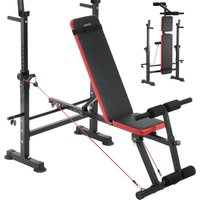
SJ7805 - Fitness Equipment Vevor - Free user manual and instructions
Find the device manual for free SJ7805 Vevor in PDF.


User questions about SJ7805 Vevor
0 question about this device. Answer the ones you know or ask your own.
Ask a new question about this device
Download the instructions for your Fitness Equipment in PDF format for free! Find your manual SJ7805 - Vevor and take your electronic device back in hand. On this page are published all the documents necessary for the use of your device. SJ7805 by Vevor.
USER MANUAL SJ7805 Vevor
Technical Support and E-Warranty Certificate www.vevor.com/support
Multifunctional Weightlifting bed
MODEL: SJ7805
We continue to be committed to provide you tools with competitive price. "Save Half", "Half Price" or any other similar expressions used by us only represents an estimate of savings you might benefit from buying certain tools with us compared to the major top brands and does not necessarily mean to co all categories of tools offered by us. You are kindly reminded to verify carefully when you are placing an order with us if you are actually Saving Half in comparison with the top major brands.
VEVOR®
TOUGH TOOLS, HALF PRICE
Multifunctional Weightlifting bed
MODEL:SJ7805
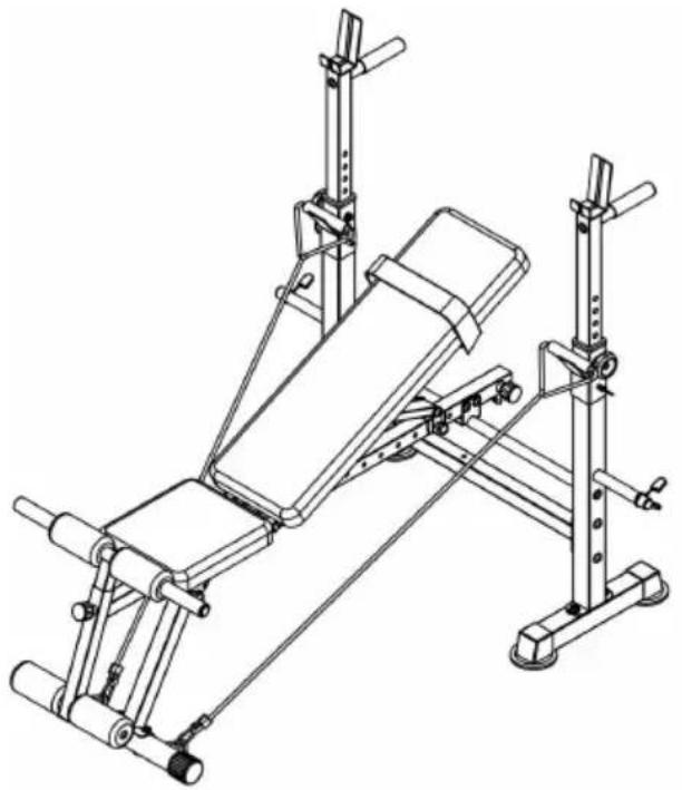
natural_image
Technical line drawing of a gym bench with adjustable arms and legs (no text or symbols)NEED HELP? CONTACT US!
Have product questions? Need technical support? Please feel free to contact us:
Technical Support and E-Warranty Certificate www.vevor.com/support
This is the original instruction, please read all manual instructions carefully before operating. VEVOR reserves a clear interpretation of o user manual. The appearance of the product shall be subject to the product you received. Please forgive us that we won't inform you ag there are any technology or software updates on our product.
Thank you very much for choosing this product.
Please read all of the instructions before using it. The information will you achieve the best possible results.
Operation safety

WARNING:
Please read all instructions before using this product It is the Owner's responsibility to ensure that all users of this product are fully aware of all warnings and precautions.
·Do not use it if you are pregnant
·Before beginning any exercise program consult your physician.
- Read all instruction before using this product.
- Keep children and pets away from sit-up bench while in use. Children should not use. The product. without adult supervision.
- Inspect and tighten all parts each time before using this sit-up bench
- Please clean this machine using damped wipes only.Do not use any cleansers.Please Consult with customer service if you have any question
- This product should be placed on a flat surface when using. Place an anti-slippery mat under the machine if needed.
- Please wear proper clothes when using this product.
- Do not use it if it is not functional or parts are not well-assembled.
·If you feel any chest pains, nausea, dizziness, or short of breadth, you should stop exercising immediately and consult your physician before continuing.
·Before use, always ensure that your product is positioned on a solid hard-flat surface.
- Store idle equipment out of reach of children and do not allow any unfamiliar with the equipment to use it. This tool is dangerous in the of untrained users.
- When using the product, the crowd of onlookers must keep adistan meters to avoid accidental injury.
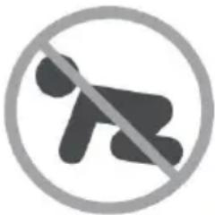
natural_image
Prohibition symbol of a person crossed out with a diagonal line, enclosed in a circle (no text or numbers present)At NO time should pets or children under the age closer to the product than 3 m (10 feet). At NO tin children under the age of 12 use the product. Child the age of 12 should not use the product without a supervision.
Exercise Plans
- Beginners are recommended to start with less reps, 5 reps as 1 set example and add reps as goes.
- Please do not exercise half an hour before /after meals or 1 hour sleep.
- Please make exercise plans.
Part List
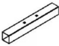
| No | Description | Qty | No | Description | Qty |
| 01 | Rear Base Tube | 2 | 25 | Flat Washer M8 | 20 |
| 02 | Rear Upright | 2 | 26 | Allen Bolt M8x20 mm | 6 |
| 03 | Rear Cross Tube | 1 | 27 | Flat Washer M10 | 20 |
| 04 | Adjustable Upright Tube | 2 | 28 | Nylon Nut M10 | 12 |
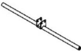
| 05 | Main Frame Supporting Tube | 1 | 29 | Carriage Bolt M10x65mm | 4 |
| 06 | Handle Bar | 2 | 30 | Allen Bolt M8x55mm | 2 |
| 07 | Weight Rest | 2 | 31 | Nylon Nut M8 | 4 |
| 08 | Main Frame | 1 | 32 | Carriage Bolt M8x65mm | 2 |
| 09 | Front Upright | 1 | 33 | Rope | 2 |
| 10 | Front Base Tube | 1 | 34 | Seat Cushion | 1 |
| 11 | Backrest Supporting Tube | 2 | 35 | Backrest Cushion | 1 |
| 12 | Backrest Adjustable Tube | 1 | 36 | Round End Cap 25mm | 6 |
| 13 | Adjustable Piece | 1 | 37 | Leg Extension | 1 |
| 14 | Round End Cap 50mm | 2 | 38 | Adjustable Tube | 1 |
| 15 | End Cap 35x35mm | 1 | 39 | Long Foam Tube | 1 |
| 16 | End Cap 25x25mm | 8 | 40 | Short Foam Tube | 1 |
| 17 | Square End Cap 50x50mm | 4 | 41 | Weight Plate post | 2 |
| 18 | Spacer | 2 | 42 | Spring Clip | 2 |
| 19 | Foam Grip | 2 | 43 | Knob Bolt | 2 |
| 20 | Lock Pin Φ10x65mm | 2 | 44 | Foam | 4 |
| 21 | Lock Pin Φ8x65mm | 2 | 45 | Small Foam | 2 |
| 22 | Allen Bolt M10x65mm | 6 | 46 | Adjustable Knob | 2 |
| 23 | Allen Bolt M10x165mm | 2 | 47 | Straps | 1 |
| 24 | Allen Bolt M8x40mm | 8 |
Exploded Diagram
Please note that not all of the parts and hardware you see here will used while you are
assembling the machine because some of these are already pre-install
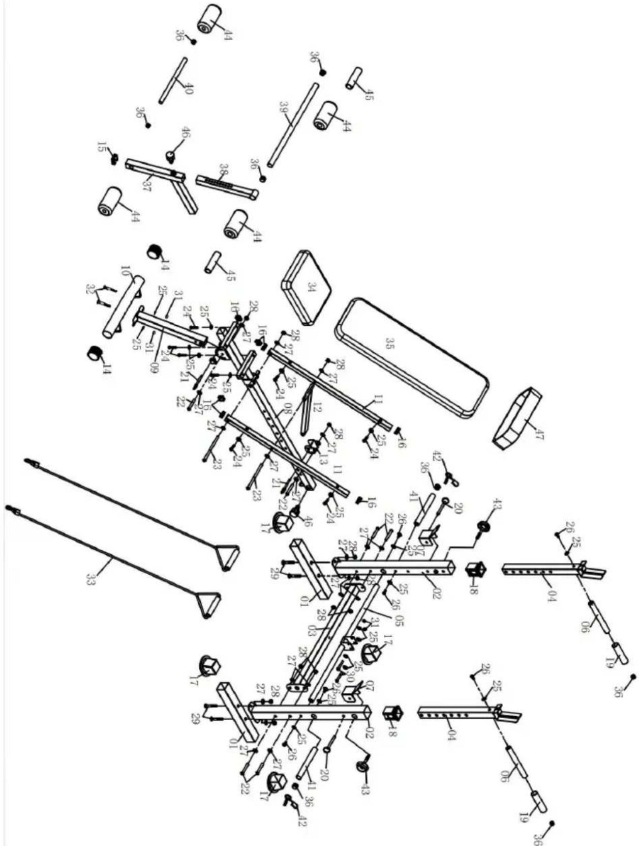
text_image
Technical diagram of a mechanical assembly with numbered components and dimension annotationsPart List
1.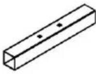 2PCS 2PCS | 2.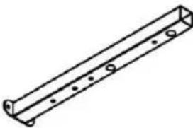 2PCS 2PCS | 3.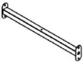 1PC 1PC | 4.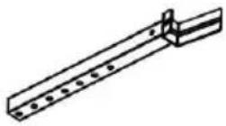 2PCS 2PCS |
5.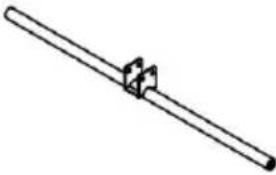 1PC 1PC | 6. 2PCS 2PCS | 7.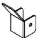 2PCS 2PCS | 8.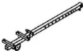 1PCS 1PCS |
9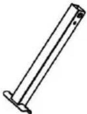 1PC 1PC | 10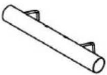 1PC 1PC | 11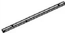 2PCS 2PCS | 12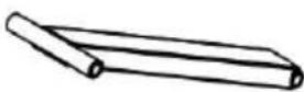 1PC 1PC |
13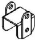 1PC 1PC | 14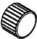 2PCS 2PCS | 15 1PCS 1PCS | 16 8PCS 8PCS |
17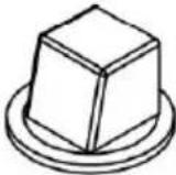 4PCS 4PCS | 18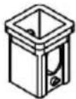 2PCS 2PCS | 19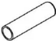 2PCS 2PCS | 20 2PCS 2PCS |
21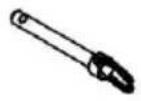 2PCS 2PCS | 22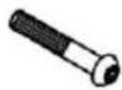 6PCS 6PCS | 23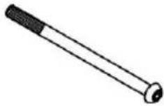 2PCS 2PCS | 24 8PCS 8PCS |
| 25[D26Y]20PCS | 26 6PCS 6PCS | 27 20PCS 20PCS | 28[G630]12PCS |
29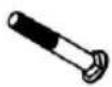 4PCS 4PCS | 30 2PCS 2PCS | 31 4PCS 4PCS | 32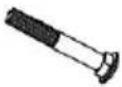 2PCS 2PCS |
33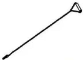 2PCS 2PCS | 34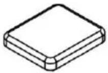 1PC 1PC | 35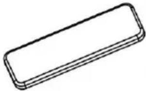 1PC 1PC | 36 6PCS 6PCS |
37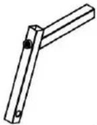 1PC 1PC | 38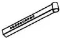 1PC 1PC | 39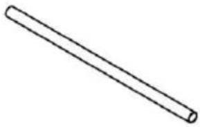 1PC 1PC | 40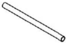 1PC 1PC |
41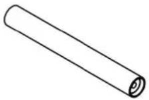 2PCS 2PCS | 42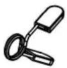 2PCS 2PCS | 43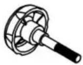 2PCS 2PCS | 44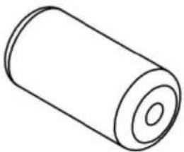 4PCS 4PCS |
45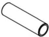 2PCS 2PCS | 46 2PCS 2PCS | 47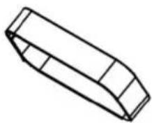 1PC 1PC |
NOTE:
To avoid misalignment due to over-tightening, please do not use a w at this time.
Hand-tightening for now will help ensure easy assembly.
Wrench-tightening should be performed after all parts are assembled to ensure all nuts, bolts, and parts are tightly secured before use.
With the help of an assistant.
Assembly
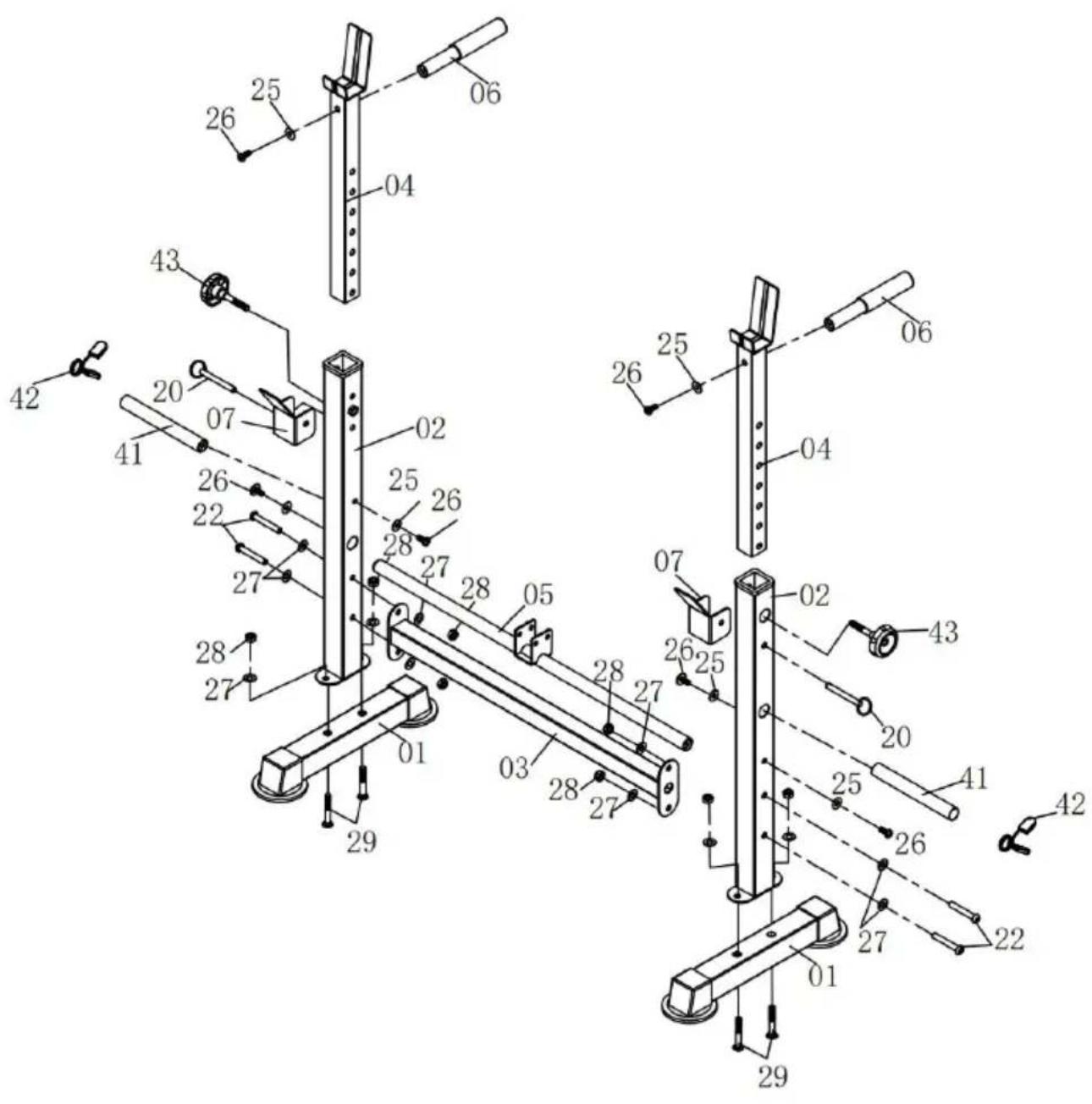
Step 1:
A) Attach two Rear Uprights (02) to two Rear Base tubes (01) total Carriage Bolts (29),
four Flat Washers (27) and four Nylon Nuts (28).
B) Insert Main Frame Supporting Tube (05) to the hole of two Rear Uprights (02), secure them by
using two Allen Bolts (26) and two Flat Washers (25) form outside.
Attach the Rear Cross Tube (03) to Rear Uprights (02), secure with four Allen Bolts (22),
eight Flat Washers (27) and four Nylon Nuts (28).
C) Attach two Weight Plate Posts (41) to both two Rear Uprights (02) two Allen Bolts (26)
and two Flat Washers (25), attach the Spring Clips (42) to Weight P Posts (41).
D) Insert Adjustable Upright Tubes (04) to Rear Uprights (02), choose appropriate hole
position then insert the Knob Bolt (43), attach the Weight Rest (07) Uprights (02) then
insert the Lock Pin (20). Attach the Handle Bar (06) to the Adjustable Upright Tubes (04) using one Allen Bolts (26) and one Flat Washers Repeat this process on the other side.
text_image
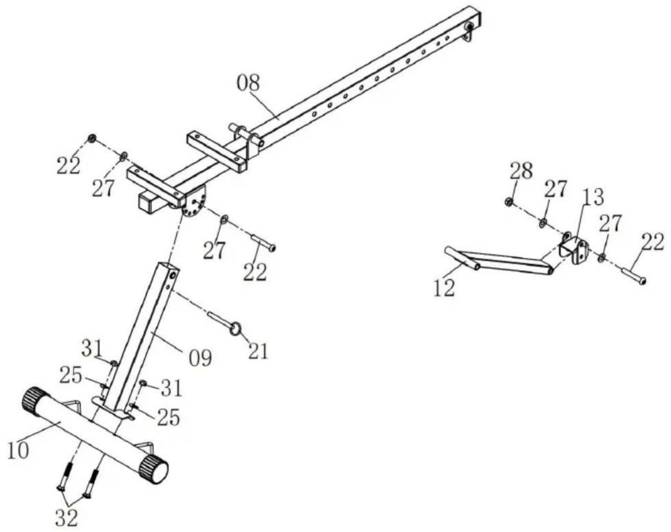
Technical diagram of a mechanical assembly with numbered components and labeled partsStep 2:
A) Attach the Front Upright (09) to Front Base Tube (10) by using t Carriage Bolts (32), two Flat
Washers (25) and two Nylon Nuts (31)
Attach the Front Upright (09) to the front side of Main Frame (08) u Allen Bolts (22), two
Flat Washers (27) and one Nylon Nut (28), then insert the Lock Pin B) Insert the Backrest Adjustable Tube (12) to Adjustable Piece (13) one Allen Bolts (22),
two Flat Washers (27) and one Nylon Nuts (28).
text_image
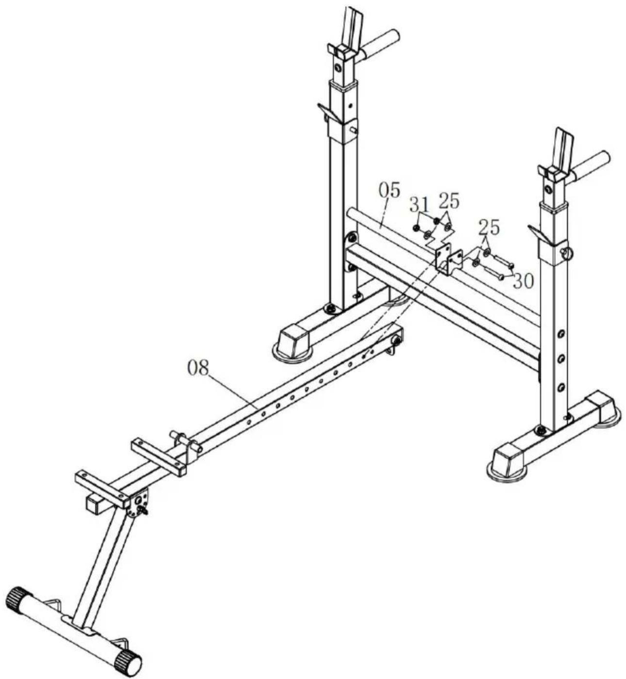
Technical diagram of a mechanical linkage system with numbered components and dashed lines indicating assembly or assembly steps.Step 3:
Attach rear side of Main Frame (08) to Main Frame Supporting Tube using two Allen Bolts
(30), four Flat Washers (25) and two Nylon Nuts (31).
text_image
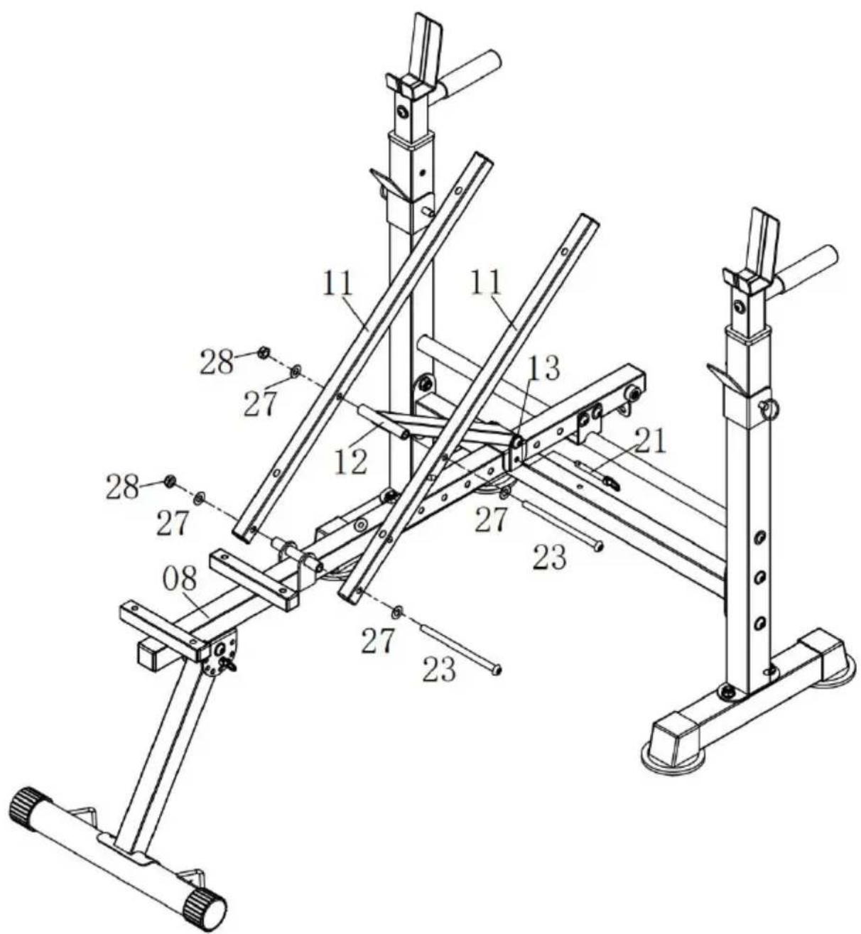
05 31 25 25 30 08Step 4:
Attach two Backrest Supporting Tubes (11) to the welded rod of Mair Frame (08) secure by one Allen Bolt (23), two Flat Washers (27) an Nylon Nut (28).
Place the Backrest Adjustable Tube (12) in the middle of the Backrest Supporting Tubes (11) and insert one Allen Bolt (23), two Flat Washes and one Nylon Nut (28) to fix.
Attach the Adjustable Piece (13) to the hole of Main Frame (08) using Pin (21)
text_image
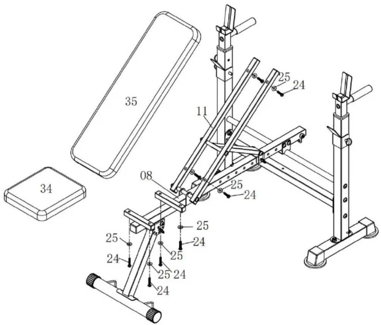
Technical diagram of a mechanical assembly with numbered components for identificationStep 5:
Attach the Seat Cushion (34) to the Main Frame (08) by using four Bolts (24) and four Flat Washers (25).
Attach the Backrest Cushion (35) to the Backrest Supporting Tubes (1 using four Allen Bolts (24) and four Flat Washers (25).
text_image
35 11 25 24 08 25 24 25 24 25 24 25 24 25 24 34Step 6:
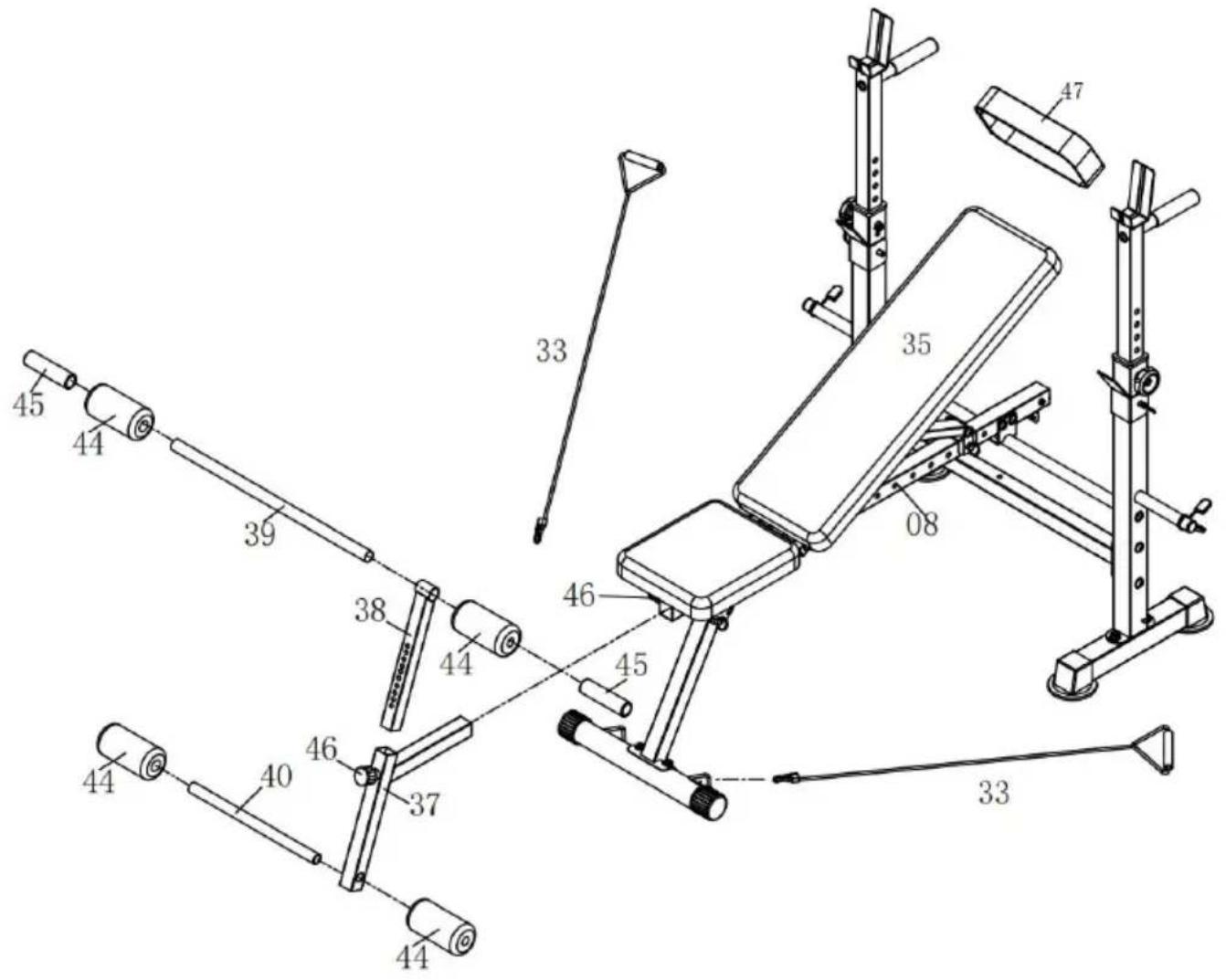
A) Attach Leg Extension (37) to Main Frame (08) secure with Adjusted Knob (46).
Insert Adjustable Tube (38) to Leg Extension (37) secure with Adjusta Knob (46)
B) Slide Long Foam Tube (39) to Adjustable Tube (38), insert Foams and Small Foams (45) to each side of Foam Tube (39). Slide Short F Tube (40) to Adjustable Tube (38), insert Foams (44) to each side of Tube (40).
C) Attach two Ropes (33) to the Front Base Tube (10). Attach the St (47) to Backrest Cushion (35).
text_image
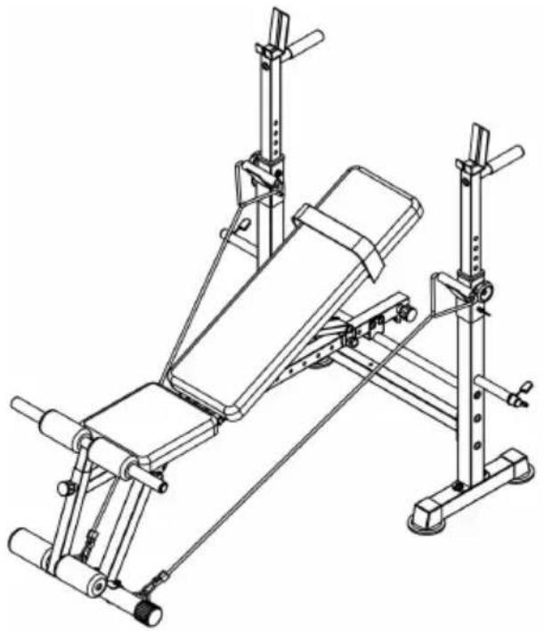
Technical diagram of a stationary exercise machine with labeled parts and numbered componentsTHE ASSEMBLY PROCESS IS NOW COMPLETE.
For your safety, Please tighten the screw and adjust it to the appropriate position.
Please visually and functionally inspect and test the unit after assemb complete.
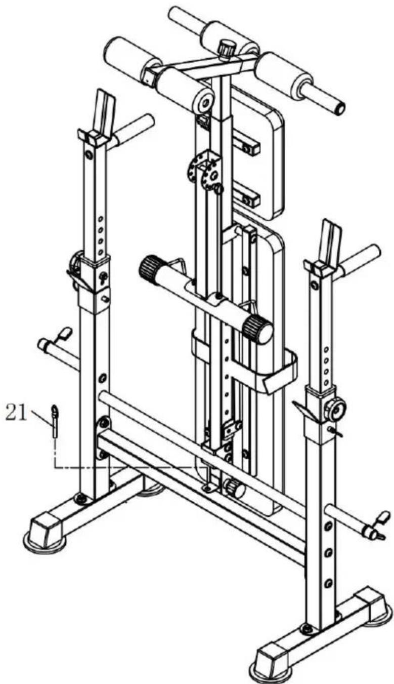
Step 7:
The following figure shows the folded state of the product.
natural_image
Technical line drawing of a mechanical lifting device with multiple arms and legs (no text or symbols)NOTE : The Maximum Weight Capacity for this product is 600 lbs of 272kgs. Only one person should use this piece of equipment at one
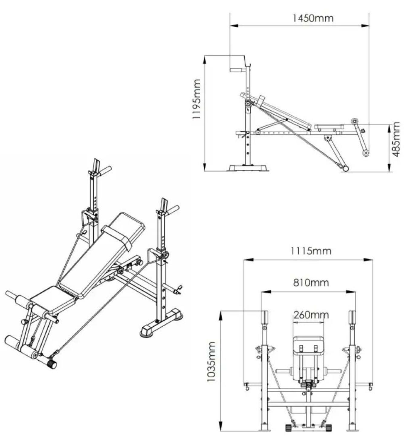
Product size chart
Cleaning and disinfection
- Wipe the surface with a wet cotton cloth.
- Check the screws regularly every 3 months for loosening and tight the screws
Manufacturer: Shanghaimuxinmuyeyouxiangongsi
Address: Shuangchenglu 803nong11hao1602A-1609shi, baoshanqu, shanghai 200000 CN.
Imported to AUS: SIHAO PTY LTD. 1 ROKEVA STREETEASTWOOD NSW 2122 Australia
Imported to USA: Sanven Technology Ltd. Suite 250, 9166 Anaheim Place, Rancho Cucamonga, CA 91730
| UK | REP |
YH CONSULTING LIMITED. C/O YH Consultin Limited Office 147, Centurion House, London Road, Staines-upon-Thames, Surrey, TW18 4A>
| EC | REP |
Technical Support and E-Warranty Certificate
www.vevor.com/support
VEVOR®
TOUGH TOOLS, HALF PRICE
Multifunctional Weightlifting bed
MODÈLE: SJ78 05
natural_image
Technical line drawing of a gym bench with adjustable arms and legs (no text or symbols)BESOIN D'AIDE? CONTACTEZ-NOUS!
natural_image
Prohibition symbol of a person crossed out, no text or numbers presentAt NO time should pets or children under the age closer to the product than 3 m (10 feet). At NO tin children under the age of 12 use the product. Child the age of 12 should not use the product without a supervision.
Exercise Plans
| No | Description | Qty | No | Description | Qty |
| 01 | Rear Base Tube | 2 | 25 | Flat Washer M8 | 20 |
| 02 | Rear Upright | 2 | 26 | Allen Bolt M8x20 mm | 6 |
| 03 | Rear Cross Tube | 1 | 27 | Flat Washer M10 | 20 |
| 04 | Adjustable Upright Tube | 2 | 28 | Nylon Nut M10 | 12 |
| 05 | Main Frame Supporting Tube | 1 | 29 | Carriage Bolt M10x65mm | 4 |
| 06 | Handle Bar | 2 | 30 | Allen Bolt M8x55mm | 2 |
| 07 | Weight Rest | 2 | 31 | Nylon Nut M8 | 4 |
| 08 | Main Frame | 1 | 32 | Carriage Bolt M8x65mm | 2 |
| 09 | Front Upright | 1 | 33 | Rope | 2 |
| 10 | Front Base Tube | 1 | 34 | Seat Cushion | 1 |
| 11 | Backrest Supporting Tube | 2 | 35 | Backrest Cushion | 1 |
| 12 | Backrest Adjustable Tube | 1 | 36 | Round End Cap 25mm | 6 |
| 13 | Adjustable Piece | 1 | 37 | Leg Extension | 1 |
| 14 | Round End Cap 50mm | 2 | 38 | Adjustable Tube | 1 |
| 15 | End Cap 35x35mm | 1 | 39 | Long Foam Tube | 1 |
| 16 | End Cap 25x25mm | 8 | 40 | Short Foam Tube | 1 |
| 17 | Square End Cap 50x50mm | 4 | 41 | Weight Plate post | 2 |
| 18 | Spacer | 2 | 42 | Spring Clip | 2 |
| 19 | Foam Grip | 2 | 43 | Knob Bolt | 2 |
| 20 | Lock Pin Φ10x65mm | 2 | 44 | Foam | 4 |
| 21 | Lock Pin Φ8x65mm | 2 | 45 | Small Foam | 2 |
| 22 | Allen Bolt M10x65mm | 6 | 46 | Adjustable Knob | 2 |
| 23 | Allen Bolt M10x165mm | 2 | 47 | Straps | 1 |
| 24 | Allen Bolt M8x40mm | 8 |
Diagramme éclaté
text_image
Technical diagram of a mechanical assembly with numbered components and exploded view, likely for engineering or manufacturing documentation.Part List
1. 2PCS 2PCS | 2.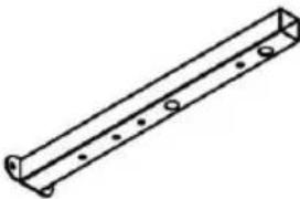 2PCS 2PCS | 3.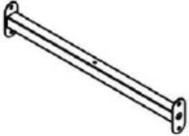 1PC 1PC | 4.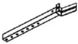 2PCS 2PCS |
5. 1PC 1PC | 6.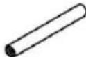 2PCS 2PCS | 7.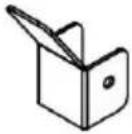 2PCS 2PCS | 8.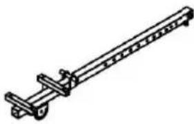 1PCS 1PCS |
9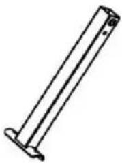 1PC 1PC | 10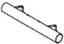 1PC 1PC | 11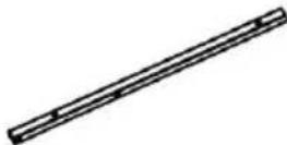 2PCS 2PCS | 12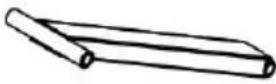 1PC 1PC |
13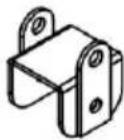 1PC 1PC | 14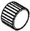 2PCS 2PCS | 15 1PCS 1PCS | 16 8PCS 8PCS |
17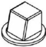 4PCS 4PCS | 18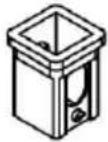 2PCS 2PCS | 19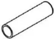 2PCS 2PCS | 20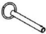 2PCS 2PCS |
| 212PCS | 226PCS | 232PCS | 248PCS |
| 25[W4002]20PCS | 26[S00H]6PCS | 2720PCS | 28[D5K0]12PCS |
| 294PCS | 302PCS | 31[T800]4PCS | 322PCS |
| 332PCS | 341PC | 351PC | 36[BWYS]6PCS |
37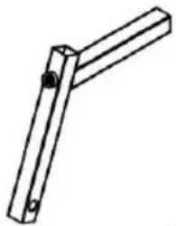 1PC 1PC | 381PC | 391PC | 401PC |
| 412PCS | 422PCS | 432PCS | 444PCS |
| 452PCS | 462PCS | 471PC |
NOTE:
text_image
Technical diagram of a mechanical assembly with numbered components and labeled partsÉtape 2 :
text_image
Technical diagram of a mechanical linkage system with numbered components and dashed lines indicating assembly or alignment.Étape 3 :
text_image
Technical diagram of a mechanical assembly with numbered components, likely a ladder or support structure.Étape 5 :
text_image
Technical diagram of a stationary exercise machine with labeled components and numbered partsLE PROCESSUS D'ASSEMBLAGE EST MAINTENANT TERMINÉ.
natural_image
Technical line drawing of a mechanical assembly with cylindrical components and mounting brackets (no text or symbols)text_image
1450mm 1195mm 485mm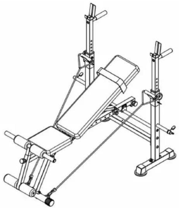
natural_image
Technical line drawing of a gym bench with adjustable arms and legs (no text or symbols)Cleaning and disinfection
Lieu, Rancho Cucamonga, CA 91730
| UK | REP |
YH CONSULTING LIMITED. C/O YH Consultin Limited Office 147, Centurion House, London Road, Staines-upon-Thames, Surrey, TW18 4A>
| EC | REP |
www.vevor.com/support
natural_image
Technical line drawing of a gym bench with adjustable arms and legs (no text or symbols)natural_image
Prohibition symbol of a person crossed out, no text or numbers presentAt NO time should pets or children under the age closer to the product than 3 m (10 feet). At NO tir children under the age of 12 use the product. Child the age of 12 should not use the product without a supervision.
Exercise Plans
| No | Description | Qty | No | Description | Qty |
| 01 | Rear Base Tube | 2 | 25 | Flat Washer M8 | 20 |
| 02 | Rear Upright | 2 | 26 | Allen Bolt M8x20 mm | 6 |
| 03 | Rear Cross Tube | 1 | 27 | Flat Washer M10 | 20 |
| 04 | Adjustable Upright Tube | 2 | 28 | Nylon Nut M10 | 12 |
| 05 | Main Frame Supporting Tube | 1 | 29 | Carriage Bolt M10x65mm | 4 |
| 06 | Handle Bar | 2 | 30 | Allen Bolt M8x55mm | 2 |
| 07 | Weight Rest | 2 | 31 | Nylon Nut M8 | 4 |
| 08 | Main Frame | 1 | 32 | Carriage Bolt M8x65mm | 2 |
| 09 | Front Upright | 1 | 33 | Rope | 2 |
| 10 | Front Base Tube | 1 | 34 | Seat Cushion | 1 |
| 11 | Backrest Supporting Tube | 2 | 35 | Backrest Cushion | 1 |
| 12 | Backrest Adjustable Tube | 1 | 36 | Round End Cap 25mm | 6 |
| 13 | Adjustable Piece | 1 | 37 | Leg Extension | 1 |
| 14 | Round End Cap 50mm | 2 | 38 | Adjustable Tube | 1 |
| 15 | End Cap 35x35mm | 1 | 39 | Long Foam Tube | 1 |
| 16 | End Cap 25x25mm | 8 | 40 | Short Foam Tube | 1 |
| 17 | Square End Cap 50x50mm | 4 | 41 | Weight Plate post | 2 |
| 18 | Spacer | 2 | 42 | Spring Clip | 2 |
| 19 | Foam Grip | 2 | 43 | Knob Bolt | 2 |
| 20 | Lock Pin Φ10x65mm | 2 | 44 | Foam | 4 |
| 21 | Lock Pin Φ8x65mm | 2 | 45 | Small Foam | 2 |
| 22 | Allen Bolt M10x65mm | 6 | 46 | Adjustable Knob | 2 |
| 23 | Allen Bolt M10x165mm | 2 | 47 | Straps | 1 |
| 24 | Allen Bolt M8x40mm | 8 |
Explosionszeichnung
text_image
Technical diagram of a mechanical assembly with numbered components and dimension annotationsPart List
| 1.2PCS | 2.2PCS | 3.1PC | 4.2PCS |
| 5.1PC | 6.2PCS | 7.2PCS | 8.1PCS |
| 91PC | 101PC | 112PCS | 12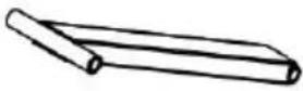 1PC 1PC |
| 131PC | 142PCS | 151PCS | 168PCS |
| 174PCS | 182PCS | 192PCS | 202PCS |
| 212PCS | 226PCS | 232PCS | 248PCS |
| 25[18WW]20PCS | 26[18HH]6PCS | 2720PCS | 28[32HZ]12PCS |
| 294PCS | 302PCS | 31[14CTA]4PCS | 322PCS |
| 332PCS | 341PC | 351PC | 36[SXT2]6PCS |
37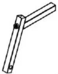 1PC 1PC | 381PC | 391PC | 401PC |
| 412PCS | 422PCS | 432PCS | 444PCS |
| 452PCS | 462PCS | 471PC |
NOTIZ:
text_image
Technical diagram of a mechanical assembly with numbered components and labeled partsSchritt 2:
text_image
Technical diagram of a mechanical linkage system with numbered components and dashed lines indicating assembly or alignment.Schritt 3:
text_image
Technical diagram of a mechanical assembly with numbered components, likely a ladder or support structure.Schritt 5:
text_image
Technical diagram of a gym machine with numbered components and labeled partsDER MONTAGEVORGANG IST JETZT ABGESCHLOSSEN.
natural_image
Technical line drawing of a mechanical assembly with cylindrical components and mounting brackets (no text or symbols)text_image
1450mm 1195mm 15mm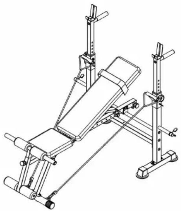
natural_image
Technical line drawing of a gym bench with adjustable arms and legs (no text or symbols)Cleaning and disinfection
YH CONSULTING LIMITED. C/O YH Consultin Limited Office 147, Centurion House, London Road, Staines-upon-Thames, Surrey, TW18 4A>
| EC | REP |
www.vevor.com/support
VEVOR®
TOUGH TOOLS, HALF PRICE
natural_image
Technical line drawing of a gym bench with adjustable arms and legs (no text or symbols)natural_image
Prohibition symbol of a person crossed out, enclosed in a circle (no text or numbers present)At NO time should pets or children under the age closer to the product than 3 m (10 feet). At NO tin children under the age of 12 use the product. Child the age of 12 should not use the product without a supervision.
Exercise Plans
| No | Description | Qty | No | Description | Qty |
| 01 | Rear Base Tube | 2 | 25 | Flat Washer M8 | 20 |
| 02 | Rear Upright | 2 | 26 | Allen Bolt M8x20 mm | 6 |
| 03 | Rear Cross Tube | 1 | 27 | Flat Washer M10 | 20 |
| 04 | Adjustable Upright Tube | 2 | 28 | Nylon Nut M10 | 12 |
| 05 | Main Frame Supporting Tube | 1 | 29 | Carriage Bolt M10x65mm | 4 |
| 06 | Handle Bar | 2 | 30 | Allen Bolt M8x55mm | 2 |
| 07 | Weight Rest | 2 | 31 | Nylon Nut M8 | 4 |
| 08 | Main Frame | 1 | 32 | Carriage Bolt M8x65mm | 2 |
| 09 | Front Upright | 1 | 33 | Rope | 2 |
| 10 | Front Base Tube | 1 | 34 | Seat Cushion | 1 |
| 11 | Backrest Supporting Tube | 2 | 35 | Backrest Cushion | 1 |
| 12 | Backrest Adjustable Tube | 1 | 36 | Round End Cap 25mm | 6 |
| 13 | Adjustable Piece | 1 | 37 | Leg Extension | 1 |
| 14 | Round End Cap 50mm | 2 | 38 | Adjustable Tube | 1 |
| 15 | End Cap 35x35mm | 1 | 39 | Long Foam Tube | 1 |
| 16 | End Cap 25x25mm | 8 | 40 | Short Foam Tube | 1 |
| 17 | Square End Cap 50x50mm | 4 | 41 | Weight Plate post | 2 |
| 18 | Spacer | 2 | 42 | Spring Clip | 2 |
| 19 | Foam Grip | 2 | 43 | Knob Bolt | 2 |
| 20 | Lock Pin Φ10x65mm | 2 | 44 | Foam | 4 |
| 21 | Lock Pin Φ8x65mm | 2 | 45 | Small Foam | 2 |
| 22 | Allen Bolt M10x65mm | 6 | 46 | Adjustable Knob | 2 |
| 23 | Allen Bolt M10x165mm | 2 | 47 | Straps | 1 |
| 24 | Allen Bolt M8x40mm | 8 |
Diagramma esploso
text_image
Technical diagram of a mechanical assembly with numbered components and exploded view, likely for engineering or manufacturing documentation.Part List
| 1.2PCS | 2.2PCS | 3.1PC | 4.2PCS |
| 5.1PC | 6.2PCS | 7.2PCS | 8.1PCS |
| 91PC | 101PC | 112PCS | 121PC |
| 131PC | 142PCS | 151PCS | 168PCS |
| 174PCS | 182PCS | 192PCS | 202PCS |
| 212PCS | 226PCS | 232PCS | 248PCS |
| 25[02W4]20PCS | 26[72WC]6PCS | 2720PCS | 28[8KRC]12PCS |
| 294PCS | 302PCS | 31[3×20]4PCS | 322PCS |
| 332PCS | 341PC | 351PC | 36[6×7]6PCS |
| 371PC | 381PC | 391PC | 401PC |
| 412PCS | 422PCS | 432PCS | 444PCS |
| 452PCS | 462PCS | 471PC |
NOTA:
text_image
Technical diagram of a mechanical assembly with numbered components and labeled partsFase 2:
text_image
Technical diagram of a mechanical assembly with numbered components, likely a ladder or support structure.Fase 5:
text_image
Technical diagram of a stationary exercise machine with labeled components and numbered partsnatural_image
Technical line drawing of a mechanical assembly with cylindrical components and mounting brackets (no text or symbols)text_image
1450mm 1195mm 15mm
natural_image
Technical line drawing of a gym bench with adjustable arms and legs (no text or symbols)Cleaning and disinfection
YH CONSULTING LIMITED. C/O YH Consultin Limited Office 147, Centurion House, London Road, Staines-upon-Thames, Surrey, TW18 4A>
| EC | REP |
Multifunctional Weightlifting bed
MODELO: SJ78 05
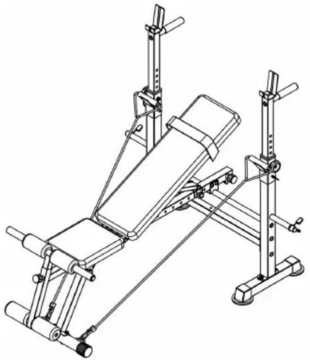
natural_image
Technical line drawing of a gym bench with adjustable arms and legs (no text or symbols)natural_image
Prohibition symbol of a walking person crossed out, enclosed in a circle (no text or numbers present)At NO time should pets or children under the age closer to the product than 3 m (10 feet). At NO tin children under the age of 12 use the product. Child the age of 12 should not use the product without a supervision.
Exercise Plans
| No | Description | Qty | No | Description | Qty |
| 01 | Rear Base Tube | 2 | 25 | Flat Washer M8 | 20 |
| 02 | Rear Upright | 2 | 26 | Allen Bolt M8x20 mm | 6 |
| 03 | Rear Cross Tube | 1 | 27 | Flat Washer M10 | 20 |
| 04 | Adjustable Upright Tube | 2 | 28 | Nylon Nut M10 | 12 |
| 05 | Main Frame Supporting Tube | 1 | 29 | Carriage Bolt M10x65mm | 4 |
| 06 | Handle Bar | 2 | 30 | Allen Bolt M8x55mm | 2 |
| 07 | Weight Rest | 2 | 31 | Nylon Nut M8 | 4 |
| 08 | Main Frame | 1 | 32 | Carriage Bolt M8x65mm | 2 |
| 09 | Front Upright | 1 | 33 | Rope | 2 |
| 10 | Front Base Tube | 1 | 34 | Seat Cushion | 1 |
| 11 | Backrest Supporting Tube | 2 | 35 | Backrest Cushion | 1 |
| 12 | Backrest Adjustable Tube | 1 | 36 | Round End Cap 25mm | 6 |
| 13 | Adjustable Piece | 1 | 37 | Leg Extension | 1 |
| 14 | Round End Cap 50mm | 2 | 38 | Adjustable Tube | 1 |
| 15 | End Cap 35x35mm | 1 | 39 | Long Foam Tube | 1 |
| 16 | End Cap 25x25mm | 8 | 40 | Short Foam Tube | 1 |
| 17 | Square End Cap 50x50mm | 4 | 41 | Weight Plate post | 2 |
| 18 | Spacer | 2 | 42 | Spring Clip | 2 |
| 19 | Foam Grip | 2 | 43 | Knob Bolt | 2 |
| 20 | Lock Pin Φ10x65mm | 2 | 44 | Foam | 4 |
| 21 | Lock Pin Φ8x65mm | 2 | 45 | Small Foam | 2 |
| 22 | Allen Bolt M10x65mm | 6 | 46 | Adjustable Knob | 2 |
| 23 | Allen Bolt M10x165mm | 2 | 47 | Straps | 1 |
| 24 | Allen Bolt M8x40mm | 8 |
Diagrama despiezado
text_image
Technical diagram of a mechanical assembly with numbered components and exploded view, likely for engineering or manufacturing documentation.Part List
| 1.2PCS | 2.2PCS | 3.1PC | 4.2PCS |
| 5.1PC | 6.2PCS | 7.2PCS | 8.1PCS |
| 91PC | 101PC | 112PCS | 121PC |
| 131PC | 142PCS | 151PCS | 16[IXCA]8PCS |
| 174PCS | 182PCS | 192PCS | 202PCS |
| 212PCS | 226PCS | 232PCS | 248PCS |
25 20PCS 20PCS | 266PCS | 2720PCS | 28 12PCS 12PCS |
| 294PCS | 302PCS | 31[YBGZ]4PCS | 322PCS |
| 332PCS | 341PC | 351PC | 36[2BA7]6PCS |
| 371PC | 381PC | 391PC | 401PC |
| 412PCS | 422PCS | 432PCS | 444PCS |
| 452PCS | 462PCS | 471PC |
NOTA:
text_image
Technical diagram of a mechanical assembly with numbered components and labeled partsPaso 2:
text_image
Technical diagram of a mechanical linkage system with numbered components and dashed lines indicating assembly or alignment.Paso 3:
text_image
Technical diagram of a mechanical assembly with numbered components, likely a ladder or support structure.Paso 5:
text_image
Technical diagram of a gym exercise setup with numbered components and support systemsEL PROCESO DE MONTAJE YA ESTÁ COMPLETO.
natural_image
Technical line drawing of a mechanical lifting device with rollers and clamps (no text or symbols)text_image
1450mm 1195mm 485mm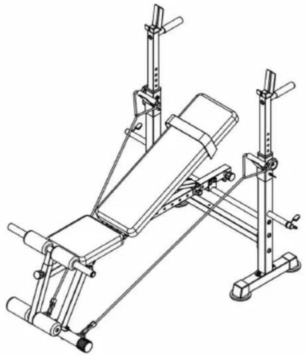
natural_image
Technical line drawing of a gym bench with adjustable arms and legs (no text or symbols)Cleaning and disinfection
YH CONSULTING LIMITED. C/O YH Consultin Limited Office 147, Centurion House, London Road, Staines-upon-Thames, Surrey, TW18 4A>
| EC | REP |
www.vevor.com/support
Multifunctional Weightlifting bed
MODELE: SJ78 05
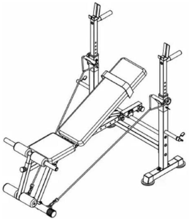
natural_image
Technical line drawing of a gym bench with adjustable arms and legs (no text or symbols)POTRZEBUJESZ POMOCY? SKONTAKTUJ SIĘ Z NAMI!
natural_image
Prohibition symbol of a person crossed out with a diagonal line, enclosed in a circle (no text or numbers present)At NO time should pets or children under the age closer to the product than 3 m (10 feet). At NO tin children under the age of 12 use the product. Child the age of 12 should not use the product without a supervision.
Exercise Plans
| No | Description | Qty | No | Description | Qty |
| 01 | Rear Base Tube | 2 | 25 | Flat Washer M8 | 20 |
| 02 | Rear Upright | 2 | 26 | Allen Bolt M8x20 mm | 6 |
| 03 | Rear Cross Tube | 1 | 27 | Flat Washer M10 | 20 |
| 04 | Adjustable Upright Tube | 2 | 28 | Nylon Nut M10 | 12 |
| 05 | Main Frame Supporting Tube | 1 | 29 | Carriage Bolt M10x65mm | 4 |
| 06 | Handle Bar | 2 | 30 | Allen Bolt M8x55mm | 2 |
| 07 | Weight Rest | 2 | 31 | Nylon Nut M8 | 4 |
| 08 | Main Frame | 1 | 32 | Carriage Bolt M8x65mm | 2 |
| 09 | Front Upright | 1 | 33 | Rope | 2 |
| 10 | Front Base Tube | 1 | 34 | Seat Cushion | 1 |
| 11 | Backrest Supporting Tube | 2 | 35 | Backrest Cushion | 1 |
| 12 | Backrest Adjustable Tube | 1 | 36 | Round End Cap 25mm | 6 |
| 13 | Adjustable Piece | 1 | 37 | Leg Extension | 1 |
| 14 | Round End Cap 50mm | 2 | 38 | Adjustable Tube | 1 |
| 15 | End Cap 35x35mm | 1 | 39 | Long Foam Tube | 1 |
| 16 | End Cap 25x25mm | 8 | 40 | Short Foam Tube | 1 |
| 17 | Square End Cap 50x50mm | 4 | 41 | Weight Plate post | 2 |
| 18 | Spacer | 2 | 42 | Spring Clip | 2 |
| 19 | Foam Grip | 2 | 43 | Knob Bolt | 2 |
| 20 | Lock Pin Φ10x65mm | 2 | 44 | Foam | 4 |
| 21 | Lock Pin Φ8x65mm | 2 | 45 | Small Foam | 2 |
| 22 | Allen Bolt M10x65mm | 6 | 46 | Adjustable Knob | 2 |
| 23 | Allen Bolt M10x165mm | 2 | 47 | Straps | 1 |
| 24 | Allen Bolt M8x40mm | 8 |
Schemat wybuchowy
text_image
Technical diagram of a mechanical assembly with numbered components and labeled partsPart List
| 1.2PCS | 2.2PCS | 3.1PC | 4.2PCS |
| 5.1PC | 6.2PCS | 7.2PCS | 8.1PCS |
| 91PC | 101PC | 112PCS | 121PC |
| 131PC | 142PCS | 15 1PCS 1PCS | 16 8PCS 8PCS |
| 174PCS | 182PCS | 192PCS | 202PCS |
| 212PCS | 226PCS | 232PCS | 248PCS |
| 2520PCS | 26[DIOK]6PCS | 2720PCS | 2812PCS |
| 294PCS | 302PCS | 31[16KA]4PCS | 322PCS |
| 332PCS | 341PC | 351PC | 36[C057]6PCS |
| 371PC | 381PC | 391PC | 401PC |
| 412PCS | 422PCS | 432PCS | 444PCS |
| 452PCS | 462PCS | 471PC |
NOTATKA:
text_image
Technical diagram of a mechanical assembly with numbered components and labeled partsKrok 2:
text_image
Technical diagram of a mechanical linkage system with numbered components and dashed lines indicating assembly or alignment.Krok 3:
text_image
Technical diagram of a mechanical assembly with numbered components, likely a ladder or support structure.Krok 5:
text_image
Technical diagram of a stationary exercise machine with labeled components and numbered partsPROCES MONTAŻU ZOSTAŁ ZAKOŃCZONY.
natural_image
Technical line drawing of a mechanical assembly with cylindrical components and mounting brackets (no text or symbols)text_image
1450mm 1195mm 15mm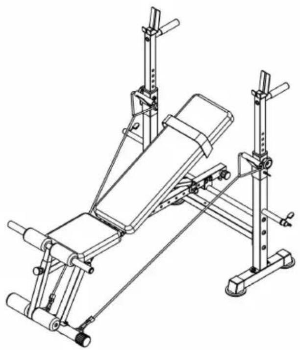
natural_image
Technical line drawing of a gym bench with adjustable arms and legs (no text or symbols)Cleaning and disinfection
YH CONSULTING LIMITED. C/O YH Consultin Limited Office 147, Centurion House, London Road, Staines-upon-Thames, Surrey, TW18 4A>
| EC | REP |
www.vevor.com/support
VEVOR®
TOUGH TOOLS, HALF PRICE
Technisch Ondersteuning en E-garantiecertificaat www.vevor.com/support
Multifunctional Weightlifting bed
MODEL: SJ78 05
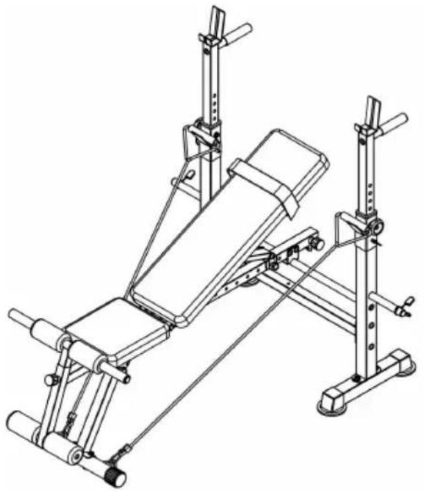
natural_image
Technical line drawing of a gym bench with adjustable arms and legs (no text or symbols)HULP NODIG? NEEM CONTACT MET ONS OP!
natural_image
Prohibition symbol of a person crossed out, no text or numbers presentAt NO time should pets or children under the age closer to the product than 3 m (10 feet). At NO tin children under the age of 12 use the product. Child the age of 12 should not use the product without a supervision.
Exercise Plans
| No | Description | Qty | No | Description | Qty |
| 01 | Rear Base Tube | 2 | 25 | Flat Washer M8 | 20 |
| 02 | Rear Upright | 2 | 26 | Allen Bolt M8x20 mm | 6 |
| 03 | Rear Cross Tube | 1 | 27 | Flat Washer M10 | 20 |
| 04 | Adjustable Upright Tube | 2 | 28 | Nylon Nut M10 | 12 |
| 05 | Main Frame Supporting Tube | 1 | 29 | Carriage Bolt M10x65mm | 4 |
| 06 | Handle Bar | 2 | 30 | Allen Bolt M8x55mm | 2 |
| 07 | Weight Rest | 2 | 31 | Nylon Nut M8 | 4 |
| 08 | Main Frame | 1 | 32 | Carriage Bolt M8x65mm | 2 |
| 09 | Front Upright | 1 | 33 | Rope | 2 |
| 10 | Front Base Tube | 1 | 34 | Seat Cushion | 1 |
| 11 | Backrest Supporting Tube | 2 | 35 | Backrest Cushion | 1 |
| 12 | Backrest Adjustable Tube | 1 | 36 | Round End Cap 25mm | 6 |
| 13 | Adjustable Piece | 1 | 37 | Leg Extension | 1 |
| 14 | Round End Cap 50mm | 2 | 38 | Adjustable Tube | 1 |
| 15 | End Cap 35x35mm | 1 | 39 | Long Foam Tube | 1 |
| 16 | End Cap 25x25mm | 8 | 40 | Short Foam Tube | 1 |
| 17 | Square End Cap 50x50mm | 4 | 41 | Weight Plate post | 2 |
| 18 | Spacer | 2 | 42 | Spring Clip | 2 |
| 19 | Foam Grip | 2 | 43 | Knob Bolt | 2 |
| 20 | Lock Pin Φ10x65mm | 2 | 44 | Foam | 4 |
| 21 | Lock Pin Φ8x65mm | 2 | 45 | Small Foam | 2 |
| 22 | Allen Bolt M10x65mm | 6 | 46 | Adjustable Knob | 2 |
| 23 | Allen Bolt M10x165mm | 2 | 47 | Straps | 1 |
| 24 | Allen Bolt M8x40mm | 8 |
Explosietekening
text_image
Technical diagram of a mechanical assembly with numbered components and labeled partsPart List
| 1.2PCS | 2.2PCS | 3.1PC | 4.2PCS |
| 5.1PC | 6.2PCS | 7.2PCS | 8.1PCS |
| 91PC | 101PC | 112PCS | 121PC |
| 131PC | 142PCS | 151PCS | 168PCS |
| 174PCS | 182PCS | 192PCS | 202PCS |
| 212PCS | 226PCS | 232PCS | 248PCS |
25 20PCS 20PCS | 26 6PCS 6PCS | 27 20PCS 20PCS | 28 12PCS 12PCS |
29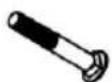 4PCS 4PCS | 30 2PCS 2PCS | 31 4PCS 4PCS | 32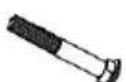 2PCS 2PCS |
| 332PCS | 34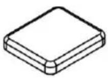 1PC 1PC | 35 1PC 1PC | 36[YQ3X]6PCS |
37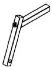 1PC 1PC | 38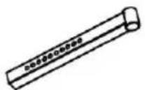 1PC 1PC | 39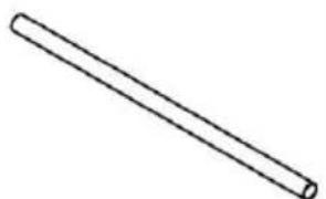 1PC 1PC | 40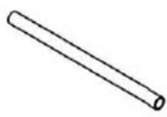 1PC 1PC |
| 412PCS | 422PCS | 432PCS | 444PCS |
| 452PCS | 462PCS | 471PC |
OPMERKING:
text_image
Technical diagram of a mechanical assembly with numbered components and labeled partsStap 2:
text_image
Technical diagram of a mechanical linkage system with numbered components and dashed lines indicating assembly or assembly steps.Stap 3:
text_image
Technical diagram of a mechanical assembly with numbered components for identificationStap 5:
text_image
Technical diagram of a stationary exercise machine with labeled components and numbered partsHET MONTAGEPROCES IS NU VOLTOOID.
natural_image
Technical line drawing of a mechanical assembly with cylindrical components and a base mount (no text or symbols)text_image
1450mm 1195mm 5mm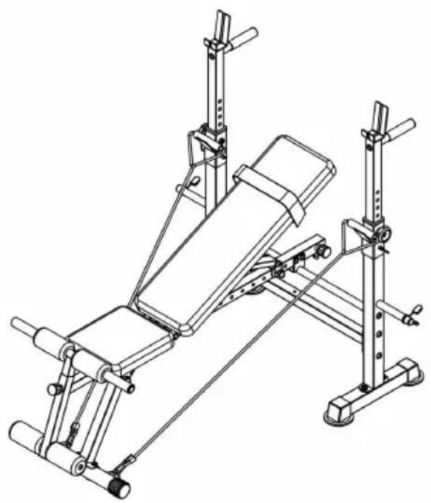
natural_image
Technical line drawing of a gym bench with adjustable arms and legs (no text or symbols)Cleaning and disinfection
YH CONSULTING LIMITED. C/O YH Consultin Limited Office 147, Centurion House, London Road, Staines-upon-Thames, Surrey, TW18 4A>
| EC | REP |
www.vevor.com/support
VEVOR®
TOUGH TOOLS, HALF PRICE
natural_image
Technical line drawing of a gym bench with adjustable arms and legs (no text or symbols)BEHÖVER HJÄLP? KONTAKTA OSS!
natural_image
Prohibition symbol showing a person crossed out of a diagonal line, enclosed in a circle (no text or numbers present)At NO time should pets or children under the age closer to the product than 3 m (10 feet). At NO tin children under the age of 12 use the product. Child the age of 12 should not use the product without a supervision.
Exercise Plans
| No | Description | Qty | No | Description | Qty |
| 01 | Rear Base Tube | 2 | 25 | Flat Washer M8 | 20 |
| 02 | Rear Upright | 2 | 26 | Allen Bolt M8x20 mm | 6 |
| 03 | Rear Cross Tube | 1 | 27 | Flat Washer M10 | 20 |
| 04 | Adjustable Upright Tube | 2 | 28 | Nylon Nut M10 | 12 |
| 05 | Main Frame Supporting Tube | 1 | 29 | Carriage Bolt M10x65mm | 4 |
| 06 | Handle Bar | 2 | 30 | Allen Bolt M8x55mm | 2 |
| 07 | Weight Rest | 2 | 31 | Nylon Nut M8 | 4 |
| 08 | Main Frame | 1 | 32 | Carriage Bolt M8x65mm | 2 |
| 09 | Front Upright | 1 | 33 | Rope | 2 |
| 10 | Front Base Tube | 1 | 34 | Seat Cushion | 1 |
| 11 | Backrest Supporting Tube | 2 | 35 | Backrest Cushion | 1 |
| 12 | Backrest Adjustable Tube | 1 | 36 | Round End Cap 25mm | 6 |
| 13 | Adjustable Piece | 1 | 37 | Leg Extension | 1 |
| 14 | Round End Cap 50mm | 2 | 38 | Adjustable Tube | 1 |
| 15 | End Cap 35x35mm | 1 | 39 | Long Foam Tube | 1 |
| 16 | End Cap 25x25mm | 8 | 40 | Short Foam Tube | 1 |
| 17 | Square End Cap 50x50mm | 4 | 41 | Weight Plate post | 2 |
| 18 | Spacer | 2 | 42 | Spring Clip | 2 |
| 19 | Foam Grip | 2 | 43 | Knob Bolt | 2 |
| 20 | Lock Pin Φ10x65mm | 2 | 44 | Foam | 4 |
| 21 | Lock Pin Φ8x65mm | 2 | 45 | Small Foam | 2 |
| 22 | Allen Bolt M10x65mm | 6 | 46 | Adjustable Knob | 2 |
| 23 | Allen Bolt M10x165mm | 2 | 47 | Straps | 1 |
| 24 | Allen Bolt M8x40mm | 8 |
Sprängt diagram
text_image
Technical diagram of a mechanical assembly with numbered components and exploded view, likely for engineering or manufacturing documentation.Part List
| 1.2PCS | 2.2PCS | 3.1PC | 4.2PCS |
| 5.1PC | 6.2PCS | 7.2PCS | 8.1PCS |
| 91PC | 101PC | 112PCS | 121PC |
| 131PC | 142PCS | 151PCS | 168PCS |
| 174PCS | 182PCS | 192PCS | 202PCS |
| 212PCS | 226PCS | 232PCS | 248PCS |
| 2520PCS | 266PCS | 2720PCS | 2812PCS |
| 294PCS | 302PCS | 314PCS | 322PCS |
| 332PCS | 341PC | 351PC | 36[x5x6]6PCS |
| 371PC | 381PC | 391PC | 401PC |
| 412PCS | 422PCS | 432PCS | 444PCS |
| 452PCS | 462PCS | 471PC |
NOTERA:
text_image
Technical diagram of a mechanical assembly with numbered components and labeled partsSteg 2:
text_image
Technical diagram of a mechanical linkage system with numbered components and dashed lines indicating assembly or alignment.Steg 3:
text_image
Technical diagram of a mechanical assembly with numbered components for identificationSteg 5:
text_image
Technical diagram of a gym equipment setup with numbered components and labeled partsMONTERINGSPROCESSEN ÄR NU AVSLUTAD.
natural_image
Technical line drawing of a mechanical lifting device with multiple arms and legs (no text or symbols)natural_image
Technical line drawing of a gym bench with adjustable arms and legs (no text or symbols)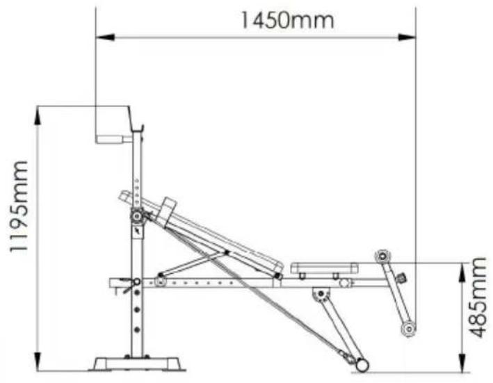
text_image
1450mm 1195mm 485mm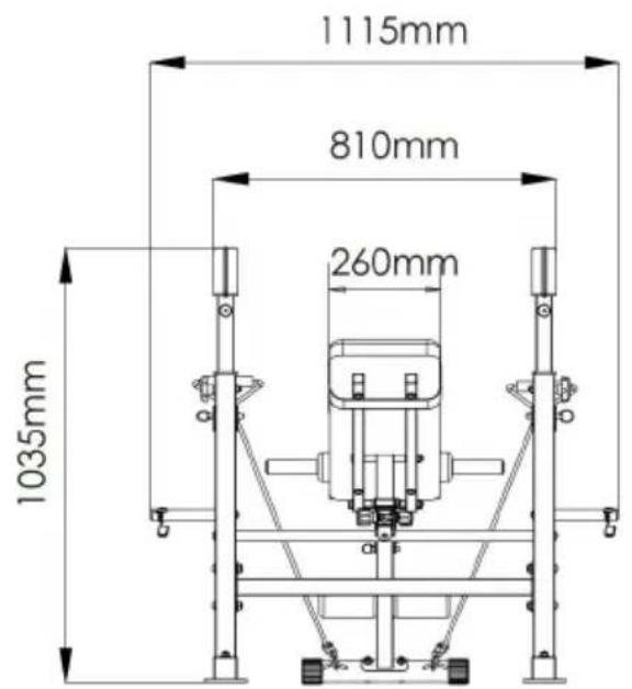
text_image
1115mm 810mm 260mm 1035mmCleaning and disinfection
YH CONSULTING LIMITED. C/O YH Consultin Limited Office 147, Centurion House, London Road, Staines-upon-Thames, Surrey, TW18 4A>
| EC | REP |
www.vevor.com/support