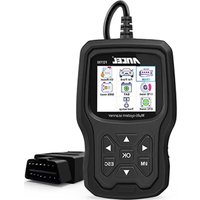
FD700 - Car diagnostic tool ANCEL - Free user manual and instructions
Find the device manual for free FD700 ANCEL in PDF.


User questions about FD700 ANCEL
0 question about this device. Answer the ones you know or ask your own.
Ask a new question about this device
Download the instructions for your Car diagnostic tool in PDF format for free! Find your manual FD700 - ANCEL and take your electronic device back in hand. On this page are published all the documents necessary for the use of your device. FD700 by ANCEL.
USER MANUAL FD700 ANCEL
To avoid body injury and damage to the device or your car, please read this manual carefully before using FD700.
- The testing process described in the manual is generally the experience of technician.
- Safety precaution is required in most of the process to avoid body injury and damage to the device or your car.
- Read the vehicle maintenance manual before use this device and follow safety precautions.
- It generates CO and other poisonous air when engine is running. To avoid this kind of hurt, please repair the car in a well-air-ventilated place.
- When the engine is running, many parts (such as the coolant fan,pulleys, fan belt etc.) rotate at high speed. To avoid serious injury,always be aware of moving parts. Keep a safe distance from theseparts as well as other potentially moving objects.
- Engine parts become very hot when the engine is running. Don't touch hot engine parts to avoid severe burns.
- Fuel and battery vapors are highly flammable. To prevent an explosion, keep all sparks, heated items and open flames away from the battery and fuel/ fuel vapors. Do not smoke near the vehicle during testing.
Coverage
- Supports the vehicles of Ford, Lincoln and Mercury after 1996 with 16PIN Socket, including F150, Transit, VAN.
- Supports OBDII/EOBD Modes of operation
Product specification
2.8'LCD,320 X 240 pixels color screen
Operating Voltage: 8V-18V
Operating Temperature: -10°C-60°C(14-140°F)
Storage Temperature: -20°C-70°C(4-158°F)
Appearance and Key Descriptions
text_image
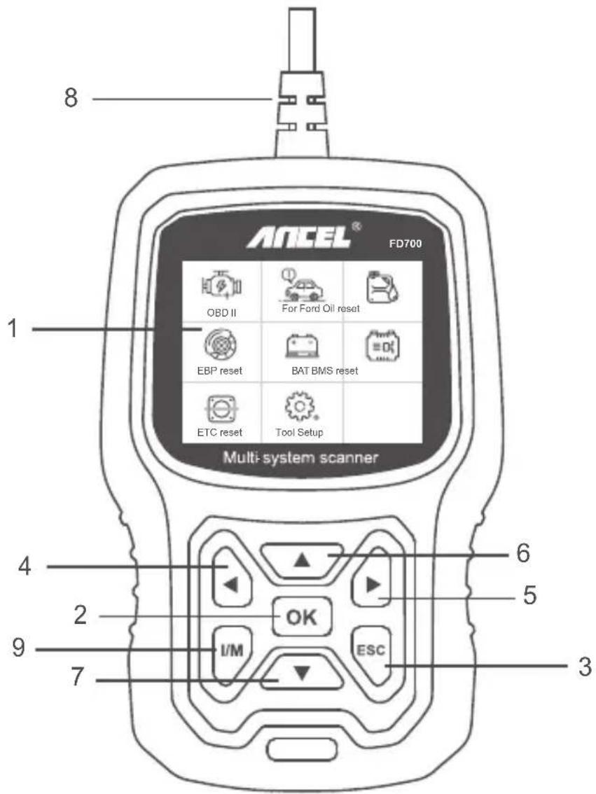
8 ANCEL® FD700 OBD II For Ford Oil reset EBP reset BAT BMS reset ETC reset Tool Setup Multi-system scanner 4 2 9 7 6 5 3 ESC- LCD DISPLAY – Indicates test results. Backlit, 320 x 240 pixels display
- OK BUTTON – Confirms a selection (or action) from a menu.
- ESC BUTTON – Cancels a selection (or action) from a menu or returns to the menu.
- LEFT SCROLL BUTTON –Move to left menu in main menu mode; When more than one screen of data is retrieved, use the left button could move to previous screens.
- RIGHT SCROLL BUTTON –Move to right menu in main menu mode; When more than one screen of data is retrieved, use the right button could move to next screen for additional data.
- UP SCROLL BUTTON – Moves up through menu items in main menu mode; When more than one screen of data is retrieved, use the up button could move to previous screens.
- DOWN SCROLL BUTTON – Moves down through menu items in main menu mode; When more than one screen of data is retrieved, use the down button could move to next screen for additional data.
- OBD-16PIN CONNECTOR – Connects the scan tool to vehicle's Data Link Connector (DLC).
- "I/M" BUTTON - A snapshot of emission-related systems states - i.e., misfire monitor, EVAP system monitor etc.

text_image
I/M Readiness IGN Spark DTC 0 MIL PdDTC 0 MIS ∅ EVAP ∅ FUE ✓ AIR ∅ CCM ✓ O2S ✗ CAT ✓ HTR ✗ HCAT ∅ EGR ∅Remarks:
MIL Yellow- Dashboard MIL ON MIL Gray-Dashboard MIL OFF
- not support
√ -complete
✗ -not complete
OPERATION INSTRUCTIONS
1. Connect FD700
1.1 Turn the ignition on. using FD700.
1.2 Locate the vehicle's 16-pin Data Link Connector (DLC).

text_image
ANCEL®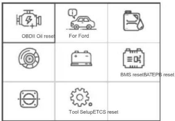
text_image
OBDII Oil reset For Ford BMS resetBATEPB reset Tool SetupETCS reset(Main interface) (Main Menu)
1.3 Main menu functions:
[OBDII]: Detect the engine system.
[For Ford]: Test all systems.
[Oil reset]: Oil change reset
[EPB reset]: EPB Brake pad reset
[BAT]: To read real Time Battery Voltage
[BMS reset]: Battery management system reset
[ETC reset]: Electric Throttle Control reset
[Tool Setup]: Language / Beeper/Instructions (Display at startup)/Unit of Measure/Skin Style/Feedback the test result
2. FD700 Features
2.1 Basic Functions
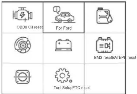
Choose [For Ford] and it displays as follows:
text_image
OBDII Oil reset For Ford BMS resetBATEPB reset Tool SetupETC reset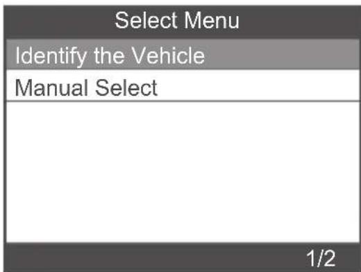
text_image
Select Menu Identify the Vehicle Manual Select 1/2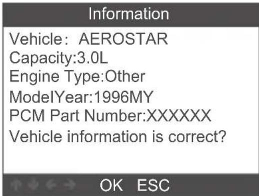
text_image
Information Vehicle: AEROSTAR Capacity:3.0L Engine Type:Other ModelYear:1996MY PCM Part Number:XXXXXX Vehicle information is correct?| Select Menu |
| System Scan |
| Manual Select |
| Special Functions |
| 1/3 |
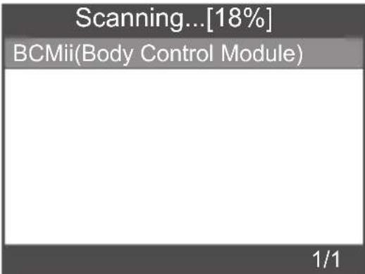
[System scan] is to scan all vehicle systems. Press [ System scan ] and it displays as follows:
text_image
Scanning...[18%] BCMii(Body Control Module) 1/1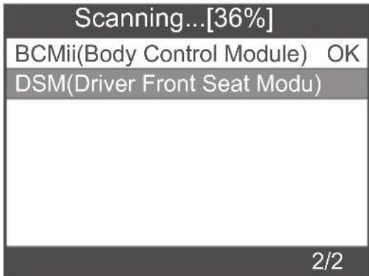
text_image
Scanning...[36%] BCMii(Body Control Module) OK DSM(Driver Front Seat Modu) 2/2| Scanning...[81%] | |
| BCMii(Body Control Module) | OK |
| PCM(Power train Control M... | OK |
| PDM(Passenger Front Door | |
| Select System Diagnose | |
| BCMii(Body Control Module) | OK |
| PCM(Power train Control M... | OK |
| 1/2 | |
[Manual select] is to display all possible systems, select one of the systems to diagnose.
Choose [Manual select] and it displays as follows:
| Select Menu |
| System Scan |
| Manual Select |
| Special Functions |
| 2/3 |
| Select System Diagnose |
| ABS(Antilock braking system) |
| BCMii(Body Control Module) |
| DDM(Driver Front Door Module) |
| DSM(Driver Front Seat Module) |
| GWM(Gateway Module A) |
| HVAC(Heating Ventiletion Air C.. ) |
| IPC(Intrument Panel Control M...) |
| 1/11 |
| Select System Diagnose |
| PCM(Power train Control Module) |
| PDM(Passenger Front Door Mo... |
| PSCM(Power Steering Control... |
| RCM(Restraint Control Module) |
| 8/11 |
2.1.1 Read Fault Codes
Choose [Read Fault Codes]. Press up or down button to check each fault code as follows:
| Select Function |
| Read Fault Codes |
| Erase Fault Codes |
| Read Datastream |
| 1/3 |
| Read Fault Codes | |
| P01F0 | 1/55 |
| Coolant Temperature RelapsedLower Than DiagnosticMonitoring Temperature | |
2.1.2 Erase Fault Codes
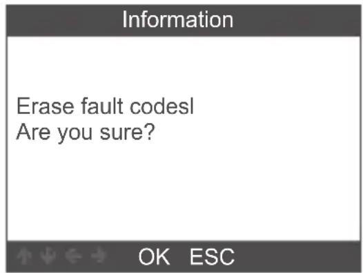
Choose [Erase Fault Codes] then press [OK] button, screen displays as follow:
text_image
Information Erase fault codes! Are you sure? OK ESCYou need to press [OK] again to clear the fault codes.
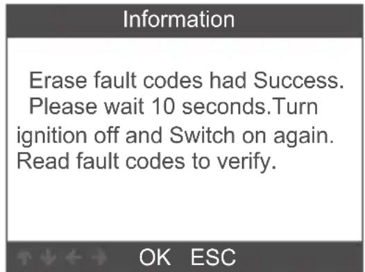
It shows as follow after clearing the fault codes.
text_image
Information Erase fault codes had Success. Please wait 10 seconds.Turn ignition off and Switch on again. Read fault codes to verify. OK ESCIf you give up clearing fault codes, please press [ESC] button.
2.1.3 Read Datastream
Choose [Read Datastream] then press [OK] button, screen displays as follows:
| Select Function |
| Read Fault Codes |
| Erase Fault Codes |
| Read Datastream |
| 3/3 |
| Datastream |
| View All Items |
| Select Items |
| 1/2 |
Choose [View All Items] then press [OK] button, screen displays as follow:
| Datastream | |
| A/C Pressure Sensor Voltage[Voits] | 1.40 |
| A/C clutch output fault detected. | NO Fault |
| CMP and CKP Synchronized | Yes |
| o2s11 Status | NO Fault |
| o2s11 is warm and ready to operate. | Yes |
| 1-5/471 | |
Choose [Select Items] then press [OK] button, screen displays as follows:
| Datastream |
| View All Items |
| Select Items |
| 2/2 |
| Select Datastream | |
| All Datastream of Page[ ] | |
| [ ] | A/C Pressure Sensor Voltage |
| [ ] | A/C clutch output fault detected. |
| [ ] | A/C Pressure sensor |
| [ ] | CMP and CKP Synchronized |
| 1-4/284 | |
Press [LEFT] and [RIGHT] buttons to page.
Press [UP] and [DOWN] buttons to select one by one.
2.2 Main special functions
Different car models have different special functions.
(Here are some common special functions. If you want to learn more about the special features of the FD700, please call or email us.)
2.2.1 Reset PCM KAM
Choose [Special Functions] and it displays as follows:
| Select Menu |
| System Scan |
| Manual Select |
| Special Functions |
| 3/3 |
| Select Function |
| Reset PCM KAM |
| Clear Transmission Adaptive T... |
| Steering Wheel Position Sensor... |
| 1/3 |
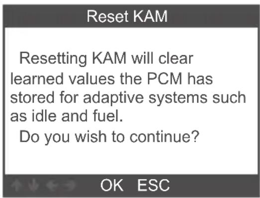
Choose [Reset PCM KAM] and it displays as follow:
text_image
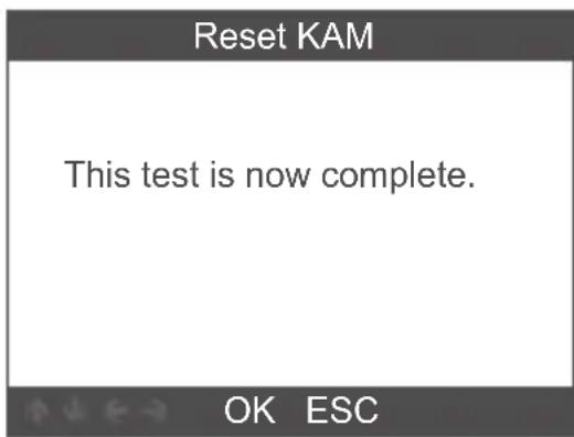
Reset KAM Resetting KAM will clear learned values the PCM has stored for adaptive systems such as idle and fuel. Do you wish to continue? OK ESCPress [OK] button to next and complete special function operation:
text_image
Reset KAM This test is now complete. OK ESC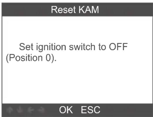
text_image
Reset KAM Set ignition switch to OFF (Position 0). OK ESC2.2.2 DPF Reset
Choose [Special Functions] and it displays as follows:
| Select Menu |
| System Scan |
| Manual Select |
| Special Functions |
| 3/3 |
| Select Function |
| ABS Service Bleed |
| Clear EGR Adaptive Tables |
| DPF Reset |
| DPF Manual Regeneration |
| 3/4 |
Press [OK] button to next:
DPF Reset
Warning
This procedure resets the DPF date.
Do you wish to continue?
OK ESC
Press [OK] button to next:
DPF Reset
Resetting completed.
OK ESC
2.2.3 Injector Quantity Adjustment
In the Engine system, choose [Special Function] and it displays as follow:
| Select Function |
| ABS Service Bleed |
| Reset TCM KAM |
| Clear Transmission Adaptive T... |
| DPF Manual Regeneration |
| IQA |
| 5/5 |
Choose [Injector Quantity Adjustment] and it displays as follows:
Injector Quantity Adjustment
Carry out this procedure to enter the new IQA date whenever a fuel in ject is replaced or to make a correction to the existing in jector IQA data currently stored in the PCM.
Injector Quantity Adjustment
On the following screen, the diagnostic tester will attempt to retrieve the in jector IQA data from the PCM allowing for verification and data entry. Perform the following :


Press [OK] button to next step:
| Injector 1 | |
| OK | |
| Delete | |
| 0 | Enter the character IQA data |
| 1 | |
| 2 | |
| 3 | |
| 4 | |
| 3/38 | ↑↓←→ OK ESC |
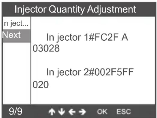
Press [OK] button, you will need to OK values manually and it displays as follow:
text_image
Injector Quantity Adjustment In ject... Next In jector 1#FC2F A 03028 In jector 2#002F5FF 020 9/9 ↑↓←→ OK ESCPress left button to character selection page down.
Press Right button to information page down.
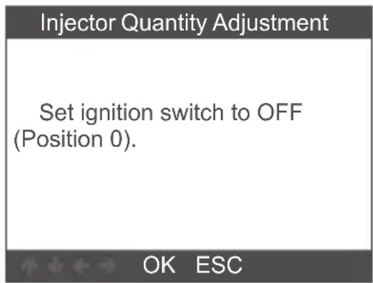
Press [OK] button to next:
text_image
Injector Quantity Adjustment Set ignition switch to OFF (Position 0). OK ESC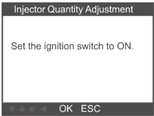
text_image
Injector Quantity Adjustment Set the ignition switch to ON. OK ESCPress [OK] button to next:
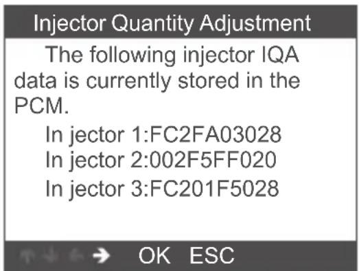
text_image
Injector Quantity Adjustment The following injector IQA data is currently stored in the PCM. In jector 1:FC2FA03028 In jector 2:002F5FF020 In jector 3:FC201F5028 OK ESCNote: Different models may have different configurations and special features maybe different.
3 OBDII Diagnose
Choose [OBDII] and it displays as follows:
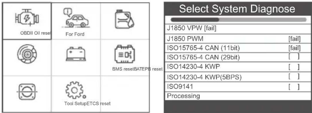
text_image
Select System Diagnose J1850 VPW [fail] J1850 PWM [fail] ISO15765-4 CAN (11bit) [fail] ISO15765-4 CAN (29bit) [ ] ISO14230-4 KWP [ ] ISO14230-4 KWP(5BPS) [ ] ISO9141 [ ] Processing3.1 Read Codes
- Select [Read Codes], then press [OK]
| Diagnostic Menu |
| Read Codes |
| Erase Codes |
| I/M Readiness |
| Data Stream |
| Evap System Test |
| Vehicle Information |
| 1/6 |
If there are no Diagnostic Trouble Codes present, the display indicates "No (pending) codes are stored in the module!" Wait a few seconds or press any key to return to the Diagnostic Menu.
2.View DTCs and their definitions on screen
(The control module number; Sequence of the DTCs; Total number of codes detected; Type of codes (Generic of Manufactur-
er specific)
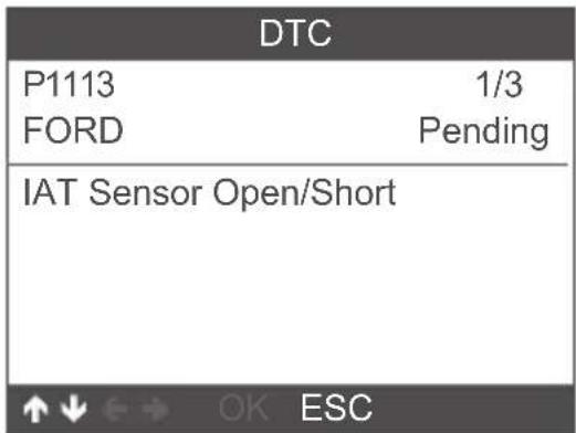
text_image
DTC P1113 1/3 FORD Pending IAT Sensor Open/Short3.2 Erase Codes
- Select [Erase codes], then press [OK]
| Diagnostic Menu |
| Read Codes |
| Erase Codes |
| I/M Readiness |
| Data Stream |
| Evap System Test |
| Vehicle Information |
| 2/6 |
- A warning message comes up asking for your confirmation.
| Erase Codes |
| Clear/Reset Emission-Related Diagnostic Information,Are you sure? |
| OK ESC |
- Press [OK] to confirm.
| Erase Codes |
| Please Turn Ignition ON with Engine Off,Press OK key to continue! |
| OK ESC |
| Erase Codes |
| Emission-Related Diagnostic Information has been Cleared! |
| OK ESC |
3.3 I/M Readiness
Select I/M Readiness option, press [OK], the screen will display as follows:
| Diagnostic Menu |
| Read Codes |
| Erase Codes |
| I/M Readiness |
| Data Stream |
| Evap System Test |
| Vehicle Information |
| 3/6 |
| I/M Readiness |
| Since DTCs Were Cleared |
| This Drive Cycle |
| 1/2 |
Use UP or Down button to select, then press [OK], the screen will display as follow
| I/M Readiness | |
| Misfire monitor OK | |
| Fuel system monitor | OK |
| Comprehensive component monitor | OK |
| Catalyst monitor | INC |
| Heated catalyst monitor | N/A |
| 1-5/10 | |
N/A means not available on this vehicle, INC means incomplete or not ready, OK means Completed or Monitor OK.
3.4 Data Stream
Choose [Data Stream] and it displays as follows:
| Diagnostic Menu |
| Read Codes |
| Erase Codes |
| I/M Readiness |
| Data Stream |
| Evap System Test |
| Vehicle Information |
| 4/6 |
| Datastream | |
| View All Items | |
| Select Items | |
| 1/2 | |
| Datastream | |
| Fuel system 1 status OL | |
| Fuel system 2 status | OL |
| Calculated LOAD Value | 0.0% |
| Engine Coolant Temperature | -31°C |
| Short Term Fuel Trim-Bank 1 | 0.0% |
| 1-5/19 | |
3.5 EVAP System Test
This function enables the conditions required to conduct an evaporative system leak test, but does not actually run the test.
The vehicle manufacturer is responsible to determine the criteria to automatically stop the test.
Before performing this function, please check the vehicle's service repair manual to determine the necessary procedures.
| Diagnostic Menu |
| Read Codes |
| Erase Codes |
| I/M Readiness |
| Data Stream |
| Evap System Test |
| Vehicle Information |
| 5/6 |
| Erase System Test |
| Evaportive system leak test not supported. |
3.6 Vehicle Information
Choose [Vehicle Information] and it displays as follows:
| Diagnostic Menu |
| Read Codes |
| Erase Codes |
| I/M Readiness |
| Data Stream |
| Evap System Test |
| Vehicle Information |
| 6/6 |
| Vehicle Information |
| Vehice Identification Number (VIN)LVSFBFAC94F020950 |
| Calibration Identifications(CID)000007550753 |
| Calibration Venfication Number (CVN)B5073064 |
| OK ESC |
4. Tool Setup
4.1 Language
Choose [Language] and it displays as follows:
 |  |  |
| OBDII Oil reset | For Ford | |
 |  |  |
 |  Tool SetupETCS reset Tool SetupETCS reset |
| Language |
| English |
| Français |
| Deutsch |
| Español |
| русский |
| Português |
| Svenska |
| Language |
| Dansk |
| Suomalainen |
| Norsk språk |
4.2 Beeper
Choose [Beeper] and it displays as follows:
| Tool Setup |
| Language |
| Beeper |
| Instructions(Display at startup) |
| Unit of Measure |
| Skin Style |
| Feedback the test result |
| 2/6 |
4.3 Instructions (Display at startup)
Choose [Instructions (Display at startup)] and it displays as follows:
| Tool Setup |
| Language |
| Beeper |
| Instructions(Display at startup) |
| Unit of Measure |
| Skin Style |
| Feedback the test result |
| 3/6 |
| Instructions(Display at startup) |
| OFF |
| ON |
| 1/2 |
4.4 Unit of measure
Choose Unit of measure and it displays as follows:
| Tool Setup |
| Language |
| Beeper |
| Instructions(Display at startup) |
| Unit of Measure |
| Skin Style |
| Feedback the test result |
| 4/6 |
| Unit of Measure |
| Metric |
| Imperial |
| 1/2 |
4.5 Skin Style
Choose Skin Style and it displays as follows:
| Tool Setup |
| Language |
| Beeper |
| Instructions(Display at startup) |
| Unit of Measure |
| Skin Style |
| Feedback the test result |
| 5/6 |
| Skin Style |
| Sky Gray |
| Gem Blue |
| 1/2 |
4.6 Feedback
If it shows connected error with vehicle or other problem during using, please using the feedback function.
Choose [Tool Setup], click on the [feedback the test result menu] and it display as follows:
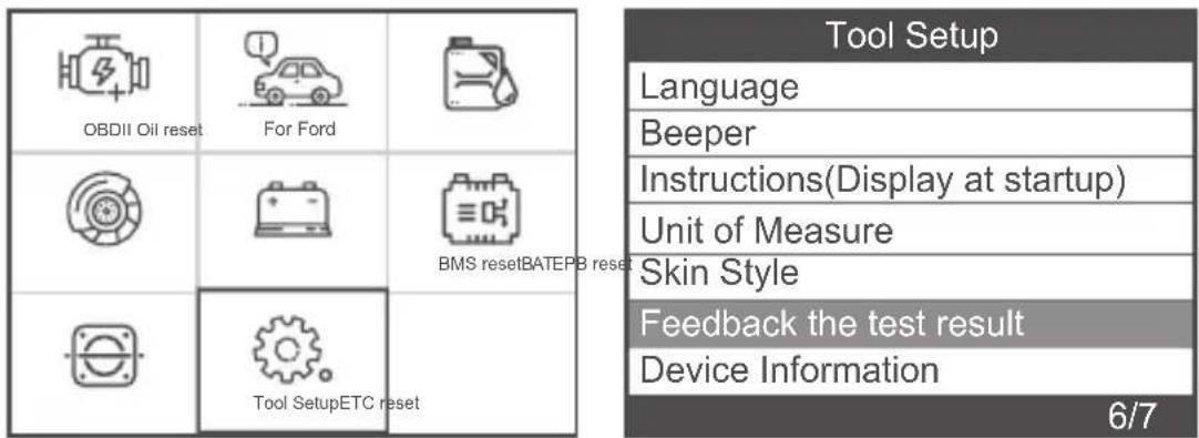
text_image
OBDII Oil reset For Ford BMS reset BATEPB reset Tool Setup Language Beeper Instructions(Display at startup) Unit of Measure Skin Style Feedback the test result Device Information 6/7Feedback the test result
Automatic recording is ready, perform the related functions that require feedback.
After the execution, disconnect the car, connect to the computer via USB, use the update.exe tool.

OK ESC
The device will display the "Feedback" prompt and exit the feedback menu. Press [Esc] to exit to the main menu.
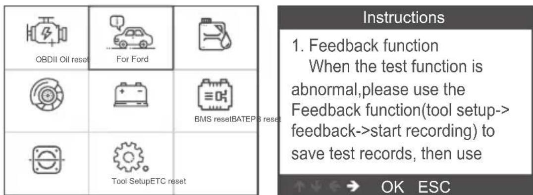
For example: If the Ford ABS system fails to connect, please follow the steps below:
text_image
OBDII Oil reset For Ford BMS resetBATEP3 reset Tool SetupETC reset Instructions 1. Feedback function When the test function is abnormal,please use the Feedback function(tool setup-> feedback->start recording) to save test records, then use ↑↓←→ OK ESCAfter exiting the feedback menu, return to the main menu: Open Ford menu, Enter the interface that failed to connect or the operation was unsuccessful during the diagnosis.
| Select Menu |
| Identify the Vehicle |
| Manual Select |
| 1/2 |
| Information |
| Vehicle: TransitCapacity:2.2LEngine Type:Duratorq-turboDiesel Common Rail InjectionModelYear:2006.5MYPCM Part Number:6C11AA |
| Select Menu |
| System Scan |
| Manual Select |
| Special Functions |
| 3/3 |
| Select Function |
| ABS Service Bleed |
| Diesel Particulate Filter Static ... |
| Fuel Injection Pump Learn |
| Fuel Injection Correction Factors |
| Reset the Diesel Particulate Filt... |
| 1/5 |
| Information |
| This Module Is Not Responding. Please Confirm: |
| *Check to ensure vehicle is equipped. |
| *Check Whether The Vehicle Wiring And Fuse Are Ok. |
Note: In the above steps, the diagnostic instrument and the vehicle must be connected.
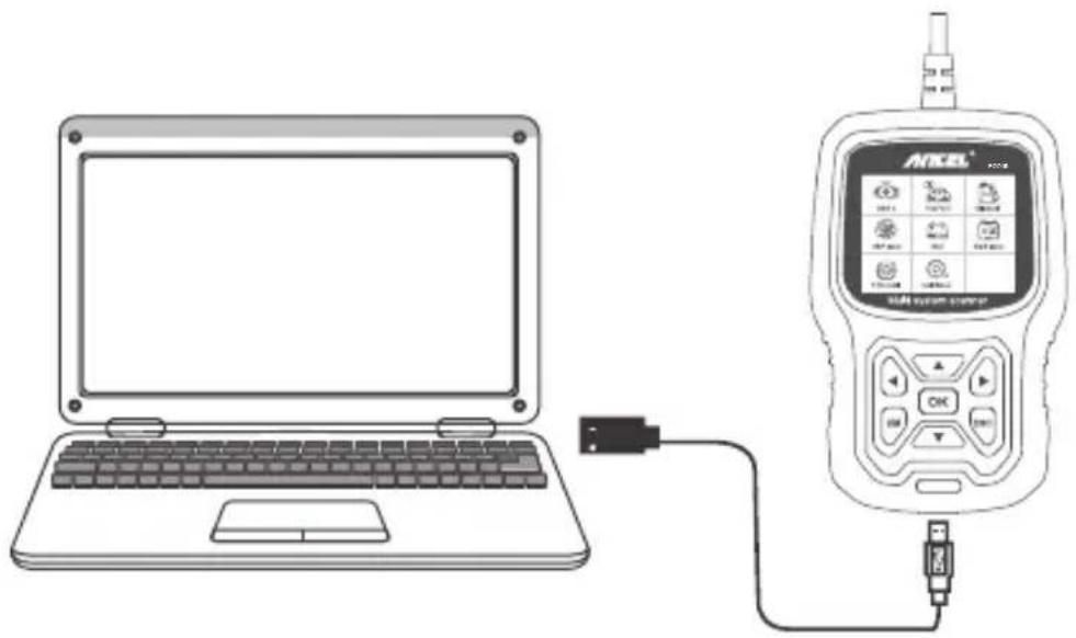
After the recording is successful, unplug the device to the computer to export the data.
text_image
Diagram showing a laptop connected to an ANKEL device with labeled ports and connection pointsConnect tool with computer, Open the upgrade files, choose "Update".
text_image
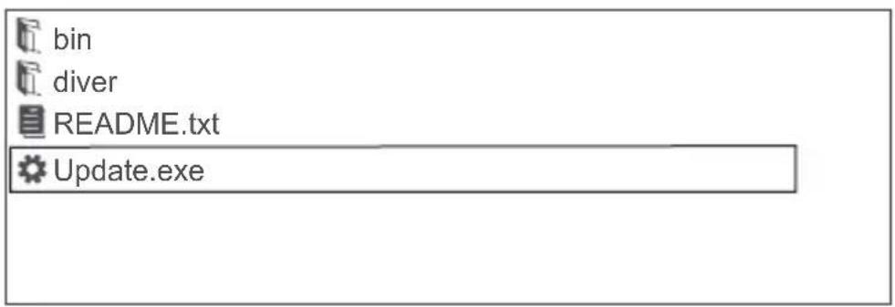
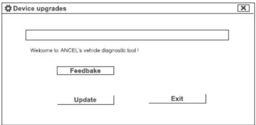
bin diver README.txt Update.exeThen pop up: "Upgrade Tools" window, click "Feedback" will appear a TXT text to explain, Please follow the instructions.
text_image
Device upgrades Welcome to ANCEL's vehicle diagnostic tool ! Feedback Update Exit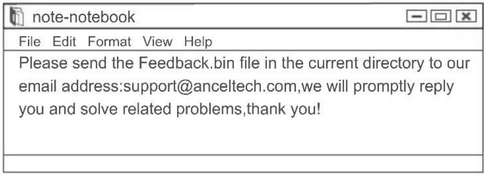
text_image
note-notebook File Edit Format View Help Please send the Feedback.bin file in the current directory to our email address:support@anceltech.com,we will promptly reply you and solve related problems,thank you!Choose the note file; send the Feedback.bin text to support@anceltech.com.
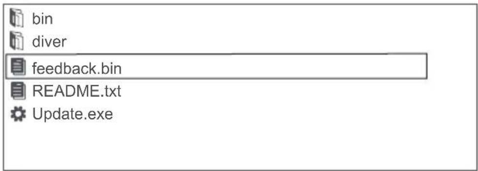
text_image
bin diver feedback.bin README.txt Update.exeRemark: In the above steps, keep the tool connected to the computer.
5. Update
- Download update software.
- Connect the devise with computer through USB cable.
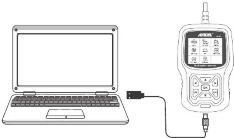
text_image
Diagram showing a laptop connected to an ATCEL medical device with labeled ports and connection points.- The update software is only supported by 7/8/10.
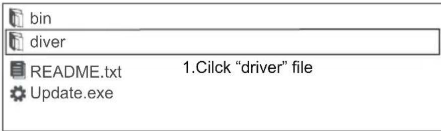
* If computer system is Windows 7, please click "install driver.bat" in the driver files to install the driver.
text_image
bin diver README.txt 1.Cilck "driver" file Update.exe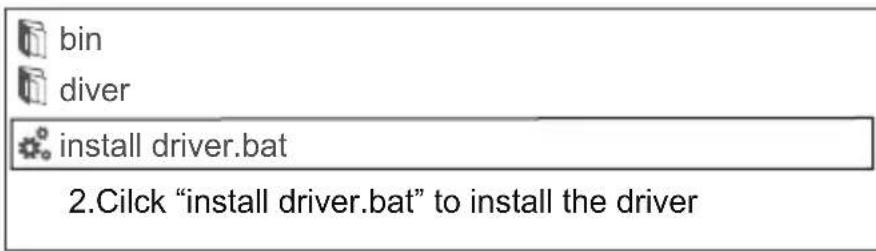
text_image
bin diver install driver.bat 2.Cilck "install driver.bat" to install the driver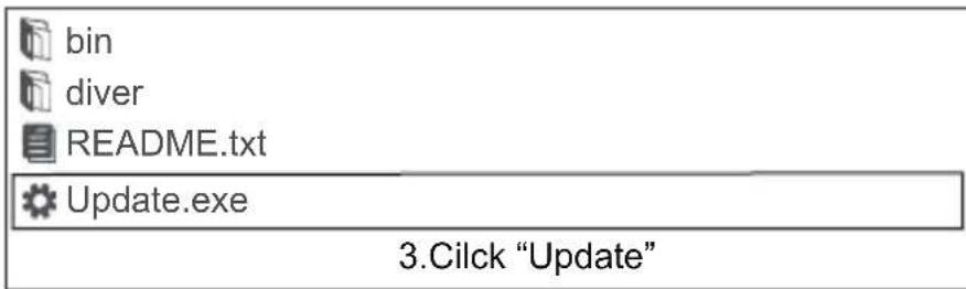
text_image
bin diver README.txt Update.exe 3.Cilck "Update"* Windows 8/10 can run update software directly.

bin

diver

README.txt

Update.exe
Windows 8/10 can run update directly
text_image
I/M Readiness IGN Spark DTC 0 MIL PdDTC 0 MIS ∅ EVAP ∅ FUE ✓ AIR ∅ CCM ✓ O2S ✗ CAT ✓ HTR ✗ HCAT ∅ EGR ∅Remarques:
MIL Yellow - Tableau de bord MIL ON
Tableau de bord gris MIL MIL OFF
text_image
OBDII Oil reset Pour Ford BMS resetBATEP8 reset Installation...ETC reset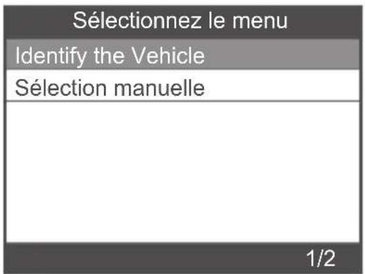
text_image
Information Vehicle: AEROSTAR Capacity:3.0L Engine Type:Other ModelYear:1996MY PCM Part Number:XXXXXX Vehicle information is correct? OK ESC
text_image
Scanning...[18%] BCMii(Body Control Module) 1/1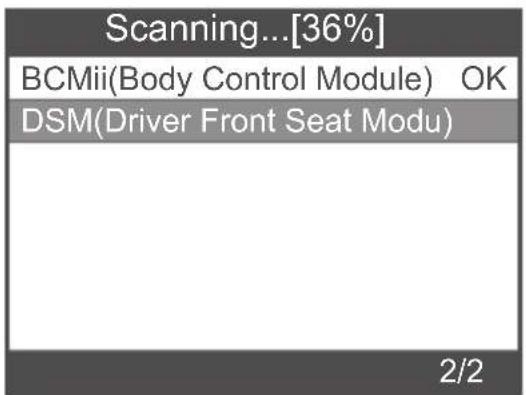
text_image
Scanning...[36%] BCMii(Body Control Module) OK DSM(Driver Front Seat Modu) 2/2| Scanning...[81%] | |
| BCMii(Body Control Module) | OK |
| PCM(Power train Control M... | OK |
| PDM(Passenger Front Door | |
| Select System Diagnose | |
| BCMii(Body Control Module) | OK |
| PCM(Power train Control M... | OK |
text_image
Lire les codes de défaut Erase fault codes had Success. Please wait 10 seconds.Turn ignition off and Switch on again. Read fault codes to verify. ↑↓←→ OK ESCtext_image
Réinitialiser PCM KAM Resetting KAM will clear learned values the PCM has stored for adaptive systems such as idle and fuel. Do you wish to continue? OK ESCtext_image
Réinitialiser PCM KAM Réiniti This test is now complete. OK ESC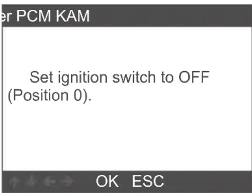
text_image
er PCM KAM Set ignition switch to OFF (Position 0). OK ESCThis procedure resets the DPF date.
Do you wish to continue?
OK ESC
Resetting completed.
OK ESC
2.2.3 Injector Quantity Adjustment(IQA)
Injector Quantity Adjustment
Carry out this procedure to enter the new IQA date whenever a fuel in ject is replaced or to make a correction to the existing in jector IQA data currently stored in the PCM.
Injector Quantity Adjustment
On the following screen, the diagnostic tester will attempt to retrieve the in jector IQA data from the PCM allowing for verification and data entry. Perform the following :


| Injector 1 | |
| OK | |
| Delete | |
| 0 | Enter the character IQA data |
| 1 | |
| 2 | |
| 3 | |
| 4 | |
| 3/38 | ↑↓←→ OK ESC |
text_image
Injector Quantity Adjustment n ject... Next In jector 1#FC2F A 03028 In jector 2#002F5FF 020 9/9 ↑↓←→ OK ESCtext_image
Injector Quantity Adjustment Set ignition switch to OFF (Position 0). OK ESC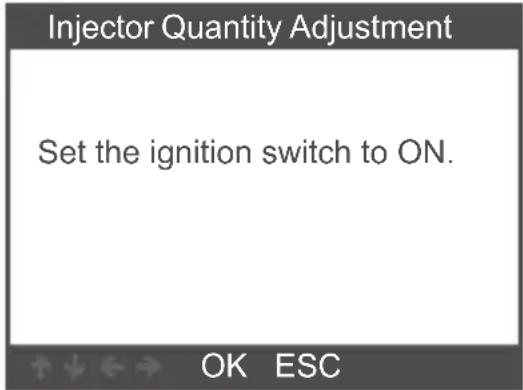
text_image
Injector Quantity Adjustment Set the ignition switch to ON. OK ESCtext_image
Injector Quantity Adjustment The following injector IQA data is currently stored in the PCM. In jector 1:FC2FA03028 In jector 2:002F5FF020 In jector 3:FC201F5028 OK ESC| Erase Codes |
| Clear/Reset Emission-Related Diagnostic Information,Are you sure? |
Please Turn Ignition ON with Engine Off, Press OK key to continue!
OK ESC
Erase Codes
Emission-Related Diagnostic Information has been Cleared!
OK ESC
3.3 I/M Readiness
| Since DTCs Were Cleared |
| This Drive Cycle |
| 1/2 |
| Misfire monitor OK | |
| Fuel system monitor | OK |
| Comprehensive component monitor | OK |
| Catalyst monitor | INC |
| Heated catalyst monitor | N/A |
| 1-5/10 | |
| Datastream |
| View All Items |
| Select Items |
| 1/2 |
| Datastream | |
| Fuel system 1 status OL | |
| Fuel system 2 status | OL |
| Calculated LOAD Value | 0.0% |
| Engine Coolant Temperature | -31°C |
| Short Term Fuel Trim-Bank 1 | 0.0% |
| 1-5/19 | |
3.5 Evap System Test
| Erase System Test |
| Evaportive system leak test not supported. |
3.6 Vehicle Information
Product specification
2.8'LCD,320 X 240 pixels color screen Operating Voltage: 8V-18V Operating Temperature: 0°C-60°C(32-140°F) Storage Temperature: -20°C-70°C(4-158°F)
text_image
I/M Readiness IGN Spark DTC 0 MIL PdDTC 0 MIS ∅ EVAP ∅ FUE ✓ AIR ∅ CCM ✓ O2S ✗ CAT ✓ HTR ✗ HCAT ∅ EGR ∅Bemerkungen:
MIL Gelb - Dashboard MIL EIN MIL Gray-Dashboard MIL OFF
text_image
Scanning...[18%] BCMii(Body Control Module) 1/1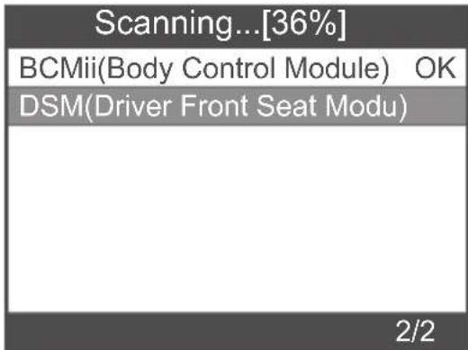
text_image
Scanning...[36%] BCMii(Body Control Module) OK DSM(Driver Front Seat Modu) 2/2| Scanning...[81%] | |
| BCMii(Body Control Module) | OK |
| PCM(Power train Control M... | OK |
| PDM(Passenger Front Door | |
| Select System Diagnose | |
| BCMii(Body Control Module) | OK |
| PCM(Power train Control M... | OK |
| 1/2 | |
text_image
Informationen Erase fault codes! Are you sure? OK ESCtext_image
Informationen Erase fault codes had Success. Please wait 10 seconds.Turn ignition off and Switch on again. Read fault codes to verify. ↑↓←→ OK ESCIf you give up clearing fault codes, please press [ESC] button.
| Datastream |
| View All Items |
| Select Items |
| 1/2 |
| Datastream | |
| A/C Pressure Sensor Voltage[Voits] | 1.40 |
| A/C clutch output fault detected. | NO Fault |
| CMP and CKP Synchronized | Yes |
| o2s11 Status | NO Fault |
| o2s11 is warm and ready to operate. | Yes |
| 1-5/471 | |
| Datastream |
| View All Items |
| Select Items |
| 2/2 |
| Select Datastream | |
| All Datastream of Page[ ] | |
| [ ] | A/C Pressure Sensor Voltage |
| [ ] | A/C clutch output fault detected. |
| [ ] | A/C Pressure sensor |
| [ ] | CMP and CKP Synchronized |
| 1-4/284 | |
Resetting KAM will clear learned values the PCM has stored for adaptive systems such as idle and fuel.
Do you wish to continue?
OK ESC
| Reset KAM |
| This test is now complete. |
| OK ESC |
| Reset KAM |
| Set ignition switch to OFF (Position 0). |
| OK ESC |
2.2.2 DPF-Reset
This procedure resets the DPF date.
Do you wish to continue?
OK ESC
Resetting completed.
OK ESC
2.2.3 Injector Quantity Adjustment
Injector Quantity Adjustment
Carry out this procedure to enter the new IQA date whenever a fuel in ject is replaced or to make a correction to the existing in jector IQA data currently stored in the PCM.
Injector Quantity Adjustment
On the following screen, the diagnostic tester will attempt to retrieve the in jector IQA data from the PCM allowing for verification and data entry. Perform the following :


Press [OK] button to next step:
| Injector 1 | |
| OK | |
| Delete | |
| 0 | Enter the character IQA data |
| 1 | |
| 2 | |
| 3 | |
| 4 | |
| 3/38 | ↑↓←→ OK ESC |
text_image
Injector Quantity Adjustment In ject... Next In jector 1#FC2F A 03028 In jector 2#002F5FF 020 9/9 ↑↓←→ OK ESCtext_image
Injector Quantity Adjustment Set ignition switch to OFF (Position 0). OK ESC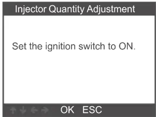
text_image
Injector Quantity Adjustment Set the ignition switch to ON. OK ESCtext_image
Injector Quantity Adjustment The following injector IQA data is currently stored in the PCM. In jector 1:FC2FA03028 In jector 2:002F5FF020 In jector 3:FC201F5028 OK ESC| Erase Codes |
| Clear/Reset Emission-Related Diagnostic Information,Are you sure? |
Please Turn Ignition ON with Engine Off, Press OK key to continue!
OK ESC
Erase Codes
Emission-Related Diagnostic Information has been Cleared!
OK ESC
3.3 I/M Readiness
| Since DTCs Were Cleared |
| This Drive Cycle |
| 1/2 |
| I/M Readiness | |
| Misfire monitor OK | |
| Fuel system monitor | OK |
| Comprehensive component monitor | OK |
| Catalyst monitor | INC |
| Heated catalyst monitor | N/A |
| 1-5/10 | |
| Datastream |
| View All Items |
| Select Items |
| 1/2 |
| Datastream | |
| Fuel system 1 status OL | |
| Fuel system 2 status | OL |
| Calculated LOAD Value | 0.0% |
| Engine Coolant Temperature | -31°C |
| Short Term Fuel Trim-Bank 1 | 0.0% |
| 1-5/19 | |
3.5 Evap System Test
| Erase System Test |
| Evaportive system leak test not supported. |
3.6 Vehicle Information
text_image
I/M Readiness IGN Spark DTC 0 MIL PdDTC 0 MIS ∅ EVAP ∅ FUE ✓ AIR ∅ CCM ✓ O2S ✗ CAT ✓ HTR ✗ HCAT ∅ EGR ∅Observaciones:
MIL Amarillo- Tablero MIL ON
MIL Gray-Dashboard MIL OFF
- no apoyo
√ -completar
✗ -sin completar
| Escaneando...[81%] | |
| BCMii(Body Control Module) | OK |
| PCM(Power train Control M... | OK |
| PDM(Passenger Front Door | |
| Seleccionar el Sistema Diagnose | |
| BCMii(Body Control Module) | OK |
| PCM(Power train Control M... | OK |
| 1/2 | |
| Select Datastream | |
| All Datastream of Page[ ] | |
| [ ] | A/C Pressure Sensor Voltage |
| [ ] | A/C clutch output fault detected. |
| [ ] | A/C Pressure sensor |
| [ ] | CMP and CKP Synchronized |
| 1-4/284 | |
Resetting KAM will clear learned values the PCM has stored for adaptive systems such as idle and fuel. Do you wish to continue?
OK ESC
text_image
Reset KAM This test is now complete. OK ESC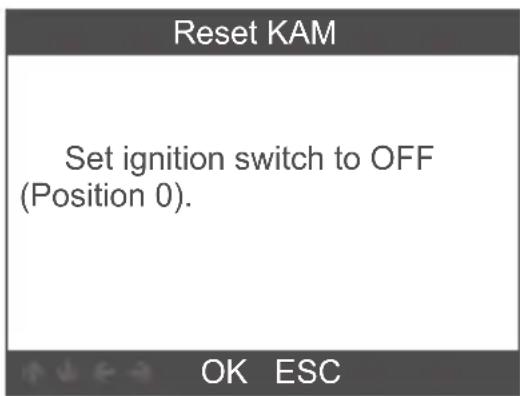
text_image
Reset KAM Set ignition switch to OFF (Position 0). OK ESC2.2.2 DPF Reset
Warning This procedure resets the DPF date. Do you wish to continue?
OK ESC
Resetting completed.
OK ESC
2.2.3 Injector Quantity Adjustment
Injector Quantity Adjustment
Carry out this procedure to enter the new IQA date whenever a fuel in ject is replaced or to make a correction to the existing in jector IQA data currently stored in the PCM.
→ OK ESC
Injector Quantity Adjustment
On the following screen, the diagnostic tester will attempt to retrieve the in jector IQA data from the PCM allowing for verification and data entry.
Perform the following :
→ OK ESC
| Injector 1 | |
| OK | |
| Delete | |
| 0 | Enter the character IQA data |
| 1 | |
| 2 | |
| 3 | |
| 4 | |
| 3/38 | ↑↓←→ OK ESC |
text_image
Injector Quantity Adjustment In ject... Next In jector 1#FC2F A 03028 In jector 2#002F5FF 020 9/9 ↑↓←→ OK ESCtext_image
Injector Quantity Adjustment Set ignition switch to OFF (Position 0). OK ESC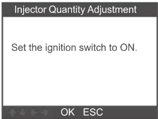
text_image
Injector Quantity Adjustment Set the ignition switch to ON. OK ESCtext_image
Injector Quantity Adjustment The following injector IQA data is currently stored in the PCM. In jector 1:FC2FA03028 In jector 2:002F5FF020 In jector 3:FC201F5028 OK ESC| Erase Codes |
| Clear/Reset Emission-Related Diagnostic Information,Are you sure? |
| Erase Codes |
| Please Turn Ignition ON with Engine Off,Press OK key to continue! |
| Erase Codes |
| Emission-Related Diagnostic Information has been Cleared! |
3.3 I/M Readiness
| I/M Readiness |
| Since DTCs Were Cleared |
| This Drive Cycle |
| 1/2 |
| I/M Readiness | |
| Misfire monitor OK | |
| Fuel system monitor | OK |
| Comprehensive component monitor | OK |
| Catalyst monitor | INC |
| Heated catalyst monitor | N/A |
| 1-5/10 | |
| Datastream | |
| View All Items | |
| Select Items | |
| 1/2 | |
| Datastream | |
| Fuel system 1 status OL | |
| Fuel system 2 status | OL |
| Calculated LOAD Value | 0.0% |
| Engine Coolant Temperature | -31°C |
| Short Term Fuel Trim-Bank 1 | 0.0% |
| 1-5/19 | |
3.5 Evap System Test
| Erase System Test |
| Evaportive system leak test not supported. |
| OK ESC |
3.6 Vehicle Information
To avoid body injury and damage to the device or your car, please read this manual carefully before using FD700.
text_image
I/M Readiness IGN Spark DTC 0 MIL PdDTC 0 MIS ∅ EVAP ∅ FUE ✓ AIR ∅ CCM ✓ O2S ✗ CAT ✓ HTR ✗ HCAT ∅ EGR ∅Osservazioni:
MIL Gray-Dashboard MIL OFF
- non supporta
√ -completare
✗ -non complete
text_image
Informazioni Vehicle: AEROSTAR Capacity:3.0L Engine Type:Other ModelYear:1996MY PCM Part Number:XXXXXX Vehicle information is correct? OK ESC| Datastream | |
| A/C Pressure Sensor Voltage[Voits] | 1.40 |
| A/C clutch output fault detected. | NO Fault |
| CMP and CKP Synchronized | Yes |
| o2s11 Status | NO Fault |
| o2s11 is warm and ready to operate. | Yes |
| Seleziona Datastream | |
| All Datastream of Page[ ] | |
| [ ] | A/C Pressure Sensor Voltage |
| [ ] | A/C clutch output fault detected. |
| [ ] | A/C Pressure sensor |
| [ ] | CMP and CKP Synchronized |
| 1-4/284 | |
| Cancellare codici |
| Clear/Reset Emission-Related Diagnostic Information,Are you sure? |
| Cancellare codici |
| Please Turn Ignition ON with Engine Off,Press OK key to continue! |
| Cancellare codici |
| Emission-Related Diagnostic Information has been Cleared! |
| I/M Readiness |
| Since DTCs Were Cleared |
| This Drive Cycle |
| 1/2 |
| I/M Readiness | |
| Misfire monitor OK | |
| Fuel system monitor | OK |
| Comprehensive component monitor | OK |
| Catalyst monitor | INC |
| Heated catalyst monitor | N/A |
| 1-5/10 | |
| Datastream | |
| Visualizza tutti Datastream | |
| Seleziona articoli | |
| 1/2 | |
| Datastream | |
| Fuel system 1 status OL | |
| Fuel system 2 status | OL |
| Calculated LOAD Value | 0.0% |
| Engine Coolant Temperature | -31°C |
| Short Term Fuel Trim-Bank 1 | 0.0% |
| 1-5/19 | |
1) This warranty is limited to the person who purchases ANCEL-products.
2) ANCEL product is warranted against defects in materials and workmanship for one year (12 months) from date of delivery to the user.
Service Procedures
If you have any questions, please contact your local store distributor or visit our website www.amceltech.com.
If it becomes necessary to return the scan tool for repair, contact your local distributor for more information.
OBDSPACE TECHNOLOGY CO.,LTD
Address: Runfeng office longhua district Shenzhen GuangDong518000 P.R.China
Tel: 0755-81751202
E-mail: support@anceltech.com
Website: www.anceltech.com






MADE IN CHINA