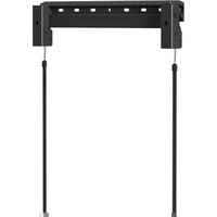
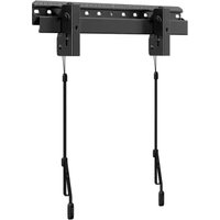
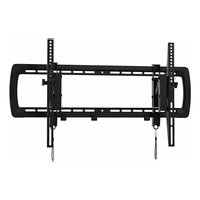
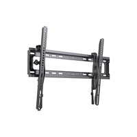
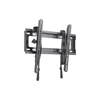
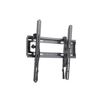
ERMLM3-01B - TV wall mount ErgoAV - Free user manual and instructions
Find the device manual for free ERMLM3-01B ErgoAV in PDF.


| Brand | ErgoAV |
| Model | ERMLM3-01B |
| Product Type | TV Wall Mount |
| VESA Compatibility | Up to 400 x 400 mm (15.7 in x 15.7 in) |
| Maximum Load (wood studs, concrete, concrete blocks) | 45 kg (100 lb) |
| Maximum Load (drywall) | 36 kg (80 lb) |
| Supported Wall Types | Wood studs, drywall, concrete, concrete blocks |
| Materials | Steel (TV brackets and wall plate) |
| Main Functions | Fixed wall mount with level adjustment and lateral shift |
| Level Adjustment | Yes, via an L-bolt at the top of the adjustable TV bracket |
| Lateral Shift | Possible on wood studs and concrete/blocks, not recommended on drywall |
| Installation | Requires drill, level, stud finder, 11 mm socket wrench, appropriate drill bits |
| Package Contents | 2 TV brackets, wall plate, bumpers, bolts (M4, M6, M8), washers, spacers, steel nails, wall anchors, drilling template |
| Care and Cleaning | Wipe with a soft, dry cloth. Periodically check the tightness of fasteners. |
| Safety Instructions | Do not exceed the maximum load. The wall must support 4 times the combined weight. Use only on specified wall types. Tighten firmly without over-tightening. Do not use outdoors. |
| Warranty | Limited manufacturer's warranty (see manual) |
| Customer Service | Phone: (877) 419-7832 (Mon-Fri 8am-8pm CST), Email: support@ergoav.com |
| Manual Languages | French, English, Spanish and others on request |
Frequently Asked Questions - ERMLM3-01B ErgoAV
User questions about ERMLM3-01B ErgoAV
0 question about this device. Answer the ones you know or ask your own.
Ask a new question about this device
Download the instructions for your TV wall mount in PDF format for free! Find your manual ERMLM3-01B - ErgoAV and take your electronic device back in hand. On this page are published all the documents necessary for the use of your device. ERMLM3-01B by ErgoAV.
USER MANUAL ERMLM3-01B ErgoAV
Medium Fixed TV Mount Instruction Manual
ERMLM3
Rev00
English 02-27
Français 28 à 53
Español 54 a 79
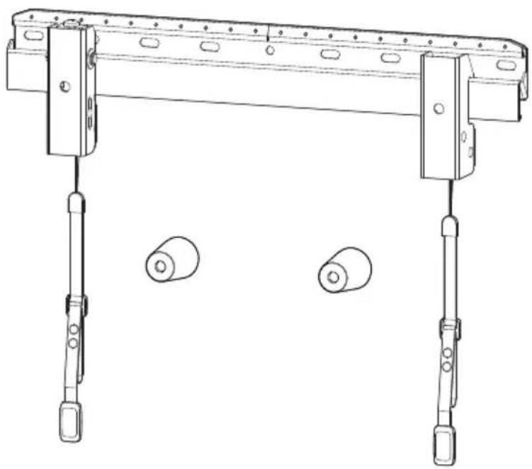
natural_image
Technical line drawing of a mechanical support frame with two vertical arms and three circular components below (no text or symbols)Thank you for choosing ErgoAV!
At ErgoAV, our goal is to add value to your AV experience by providing the highest quality products and services in the industry. We offer a 5-year warranty. If you have any questions or concerns, please contact us.

ErgoAV

9501 Louisiana Ave N, #200, Brooklyn Park, MN 55445

(877) 419-7832
Mon-Fri 8am - 8pm (CST)

support@ergoav.com

www.ergoav.com
BEFORE GETTING STARTED, LET'S MAKE SURE THIS MOUNT IS COMPATIBLE
1
Check VESA
Pattern
Compatibility
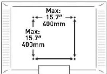
Compatible VESA Patterns:
100 x 100mm 200 x 200mm 300 x 200mm 400 x 200mm
200 x 100mm 200 x 300mm 300 x 300mm 400 x 300mm
Maximum/Minimum:
400 x 400mm (15.7 x 15.7")
100 x 100mm (3.9 x 3.9")
If this mount is not compatible, please contact product support.
2
Check Max Load
Wood Studs / Concrete / Concrete Block Walls:
100 lbs (45kg)
Drywall: 80 lbs (36kg)
If your TV weighs more, this mount is NOT compatible.

WARNING
DO NOT exceed the Max Load. Use with products heavier than the Max Load may result in failure of the mount and its accessories, causing possible damage and/or injury.
3
Verify Wall Type
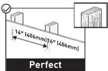
Wood Studs (with Drywall)
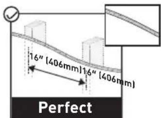
Drywall
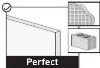
Concrete and Concrete Block Walls
02
| 5 Important Safety Information | DANGER: Please carefully read all instructions before attempting installation. If you DO NOT understand the instructions or have any questions or concerns, please call technical support or email customer service. CAUTION: Avoid the risk of personal injury and property damage! WARNING: All fasteners must be firmly tightened! • This mount can only be installed on wood studs, drywall, concrete and concrete block walls. • The wall must be capable of supporting four times the weight of the TV and mount combined. • This product contains small parts that may pose a choking hazard. • DO NOT use this product for any purpose that is NOT explicitly specified in this manual. DO NOT exceed the maximum weight capacity. We are not liable for damage or injury caused by incorrect assembly, improper mounting, or inappropriate use. • Use this mounting system only for its intended purpose as described in these instructions. DO NOT use attachments not recommended by the manufacturer. • DO NOT use outdoors. • Route cords and cables properly to avoid mechanical damage. SAVE THESE INSTRUCTIONS |

04
01 Adjustable TV Bracket
02 TV Bracket
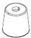
03 Bumper
04 Wall Plate
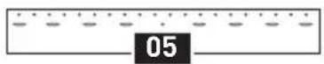
05 Wall Plate Template
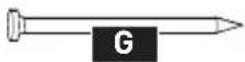
G Steel Nail
INSTALLATION
Supplied Parts and Hardware for Step 1
Not all hardware included in this package will be used.

natural_image
Line drawing of a toothbrush and toothpaste device (no text or symbols)Adjustable TV Bracket
01 k 1

natural_image
Technical line drawing of a mechanical clamp or tool with no visible text or symbolsTV Bracket
02 x 1
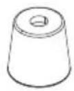
Bumper
03 x 2
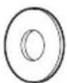
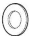
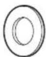
M4/M5
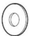
Washer
B1 × 4
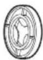
M6/M8
Washer
B2×4
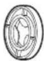
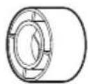
L2.5mm
Spacer
F1 k 8
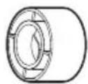
L10mm
Spacer
F2×4
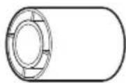
L22mm
Spacer
F3 k 4
M4
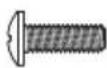
M4 x 12mm
TV Bolt
C1×4
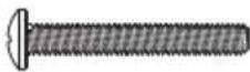
M4 x 30mm
TV Bolt
C2 k 4
M6
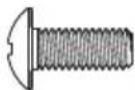
M6 x 15mm
TV Bolt
D1×4
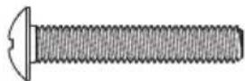
M6 x 35mm
TV Bolt
D2×4
M8
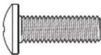
M8 x 25mm
TV Bolt
E1<4

natural_image
Close-up illustration of a threaded bolt with a flanged end (no text or symbols)M8 x 50mm
TV Bolt
E2 k 4
STEP 1 Attach the TV Brackets to Your TV
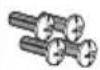
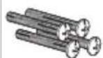
1-1 Select TV Bolts
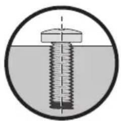
The correct bolt diameter will thread smoothly into your TV.
M4M4 M6M8M8M8
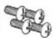
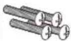
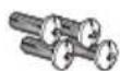
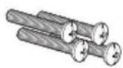
natural_image
Cross-sectional diagram of a bolt with a central hub and concentric circles (no text or labels)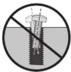
natural_image
Prohibition sign of a bolt with a diagonal line crossing through it, no text or symbols presentSave the bolts that fit (M4, M6, or M8) for Step 1-3.

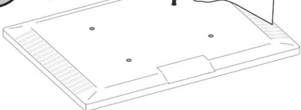
The depth of the top and bottom holes may differ.
natural_image
Isometric line drawing of a rectangular electronic device with mounting holes and a handle (no text or symbols)07
1-2 Position the TV Brackets
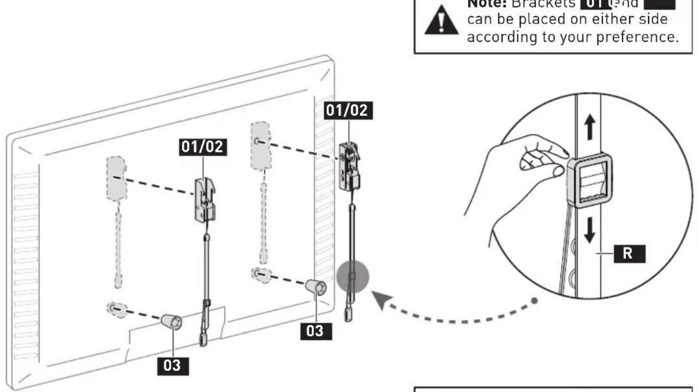

Note: If cords R are blocked by the TV, adjust the slider buckles to make them longer.
1-3 Secure the TV Brackets
For Flat-Back TV, go to Option A on page 10.
For Bump, Curved TV, Recessed Holes and Cables, go to Option B on page 11 to 12.

WARNING:
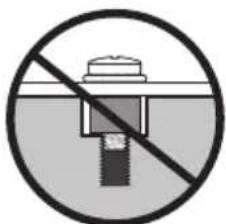
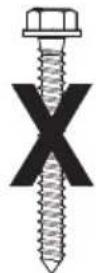
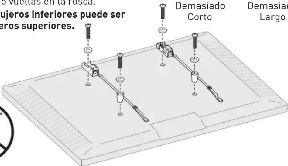
- DO NOT turn the bolt past the bottom of the hole.
- If the bolt is too short, it may not adequately support the TV.
- If the bolt is too long, it could damage the TV.
- At least 4–5 turns into the threading is required.
- The depth of the bottom holes may be different from the top holes.
natural_image
Prohibition sign showing a screw with a diagonal line crossing through it, enclosed in a circle (no text or symbols)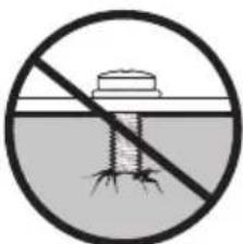
natural_image
Prohibition sign showing a dam or reservoir with no text or symbolsToo Short Too Long
natural_image
Prohibition sign of a screwdriver crossed out, enclosed in a circle (no text or symbols)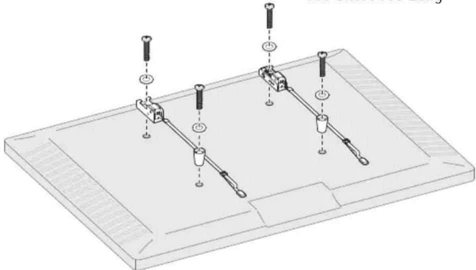
09
Option A
Use short TV bolts with washers.

Flat-Back TV

natural_image
Simple line drawing of a mechanical setup with a tool and two components on a base (no text or symbols)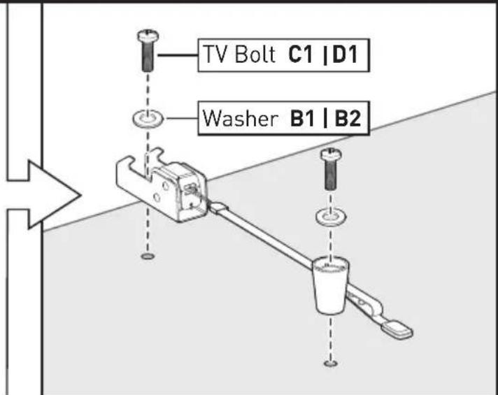
Go to Step 2 on Page 13
Option B
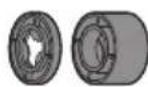
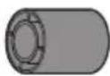
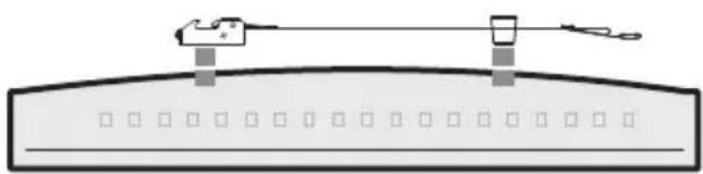
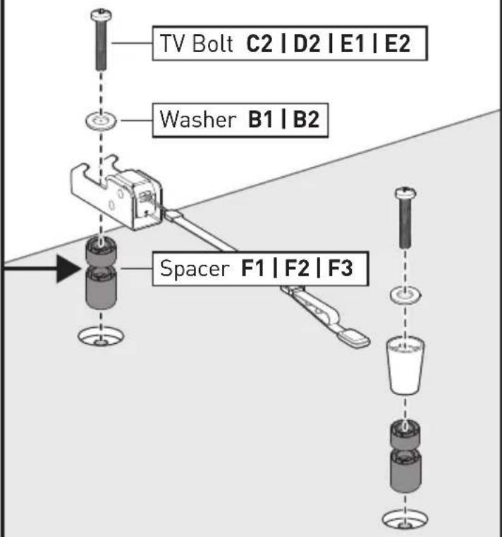
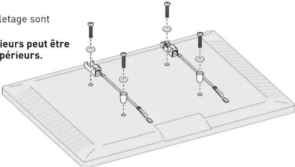
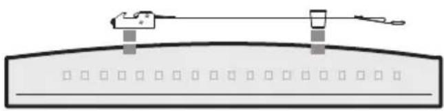
Use long TV bolts with washers and spacers to create extra space between the TV and brackets.

Bump
natural_image
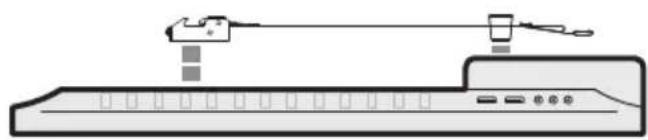
Simple line drawing of a device with a lever and ports (no text or symbols)TV with Mounting Restrictions
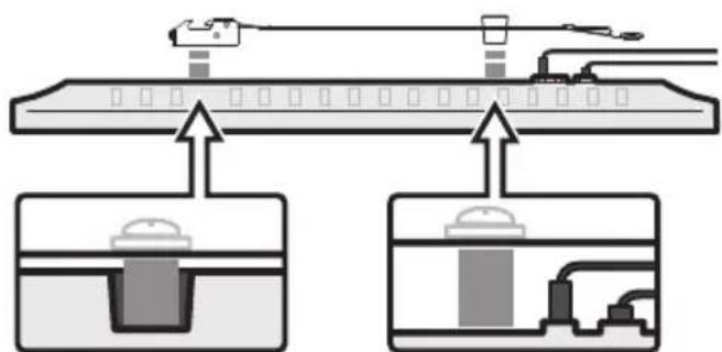
Curved TV
natural_image
Simple line drawing of a mechanical device mounted on a curved surface with no text or symbolsRecessed Holes Protruding Cables
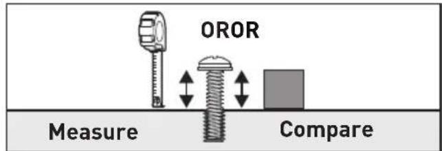
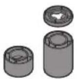
You can use a tape measure to measure the protruding bolts or hold spacers next to them to choose the right spacer combination.
Note:
There are many possible spacer combinations that can be used.


(877) 419-7832
Mon-Fri 8am - 8pm (CST)

support@ergoav.com
Supplied Parts and Hardware for Step 2
natural_image
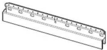
Technical line drawing of a mechanical component with evenly spaced holes and a rectangular base (no text or symbols)Wall Plate
04 x 1

Wall Plate Template
05 k 1
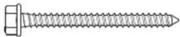
ST 1/4 × 2 3/4"
Lag Screw
A1×2

∅2.3 x 30mm
Steel Nail
G 20
CAUTION!
DO NOT use these nails on concrete and concrete block walls.
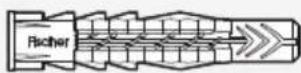
Wall Anchor
A2×2
CAUTION!
This anchor is for concrete and concrete block walls ONLY. DO NOT use them in drywall or wood studs.
STEP 2 Mount the Wall Plate on the Wall
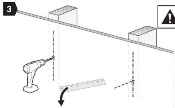
For mounting on wood stud walls, go to Option A on page 14 to 16.
For mounting on drywall, go to Option B on page 17 to 19.
For mounting on concrete and concrete block walls, go to Option C on page 20 to 22.
Option A
For Wood Stud Installation


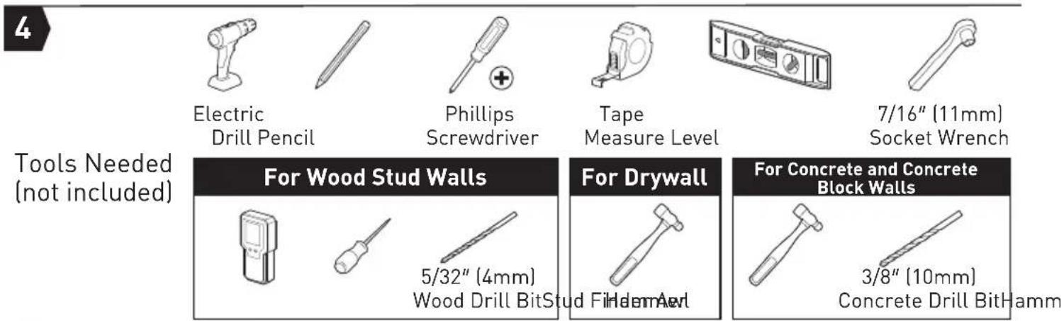
Tools Needed (Not Included)
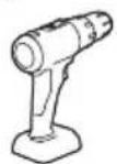
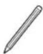
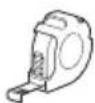
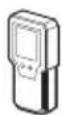

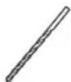
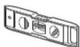
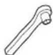
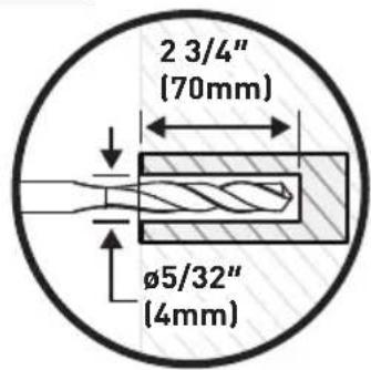
5/32" (4mm)
7/16" [11mm]
Wood Drill BitStud Fender AwlSocket Wrench
Electric Drill Pencil Tape Measure

WARNING:
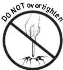
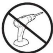
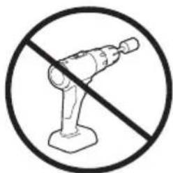
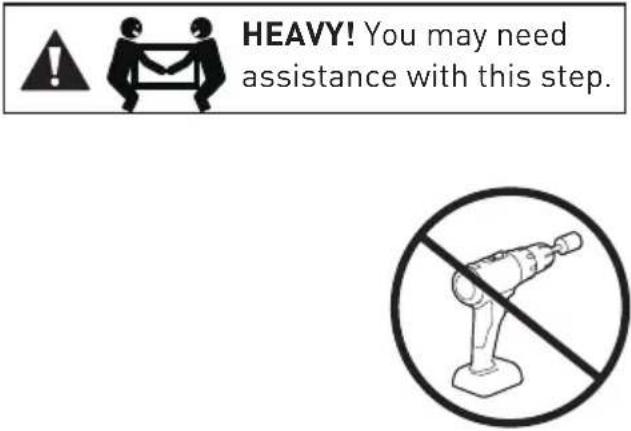
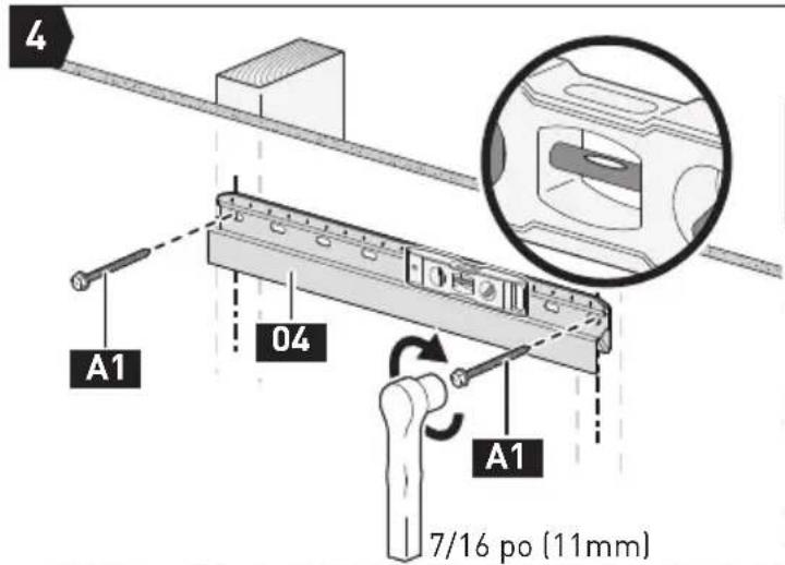
- Avoid the risk of personal injury or property damage! Tighten the lag screws A1 only until they are pulled firmly against the wall plate (DO NOT overtighten). DO NOT use a drill; only use a socket wrench.
- DO NOT use wall anchors A2 for this mounting option.
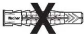
A2
Wall Anchor
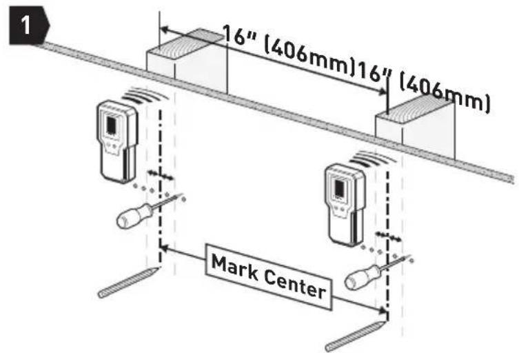
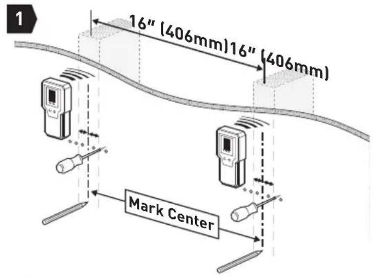
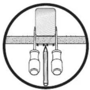
Find Studs and Mark Holes
natural_image
Simple line drawing of a mechanical setup with two bottles and a central component, enclosed in a circle (no text or symbols)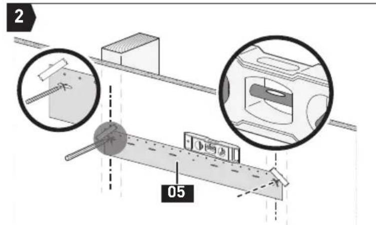
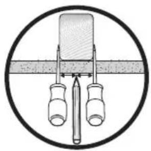
Mark 2 Hole Positions
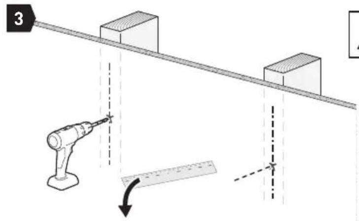

Note: Be sure to use the specified drill bit.
Drill 2 Holes
![4 A1 04 A1 7/16" [11mm]](/content/2026/04/733437/images/f1a692a126a6bccc7dbf21ecd37c6ff0a4c812c1da0e06d36247f16ddb42edc9.jpg)
Secure the Wall Plate
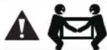
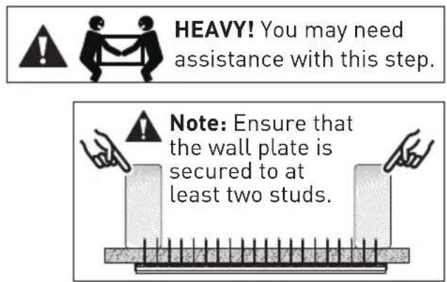
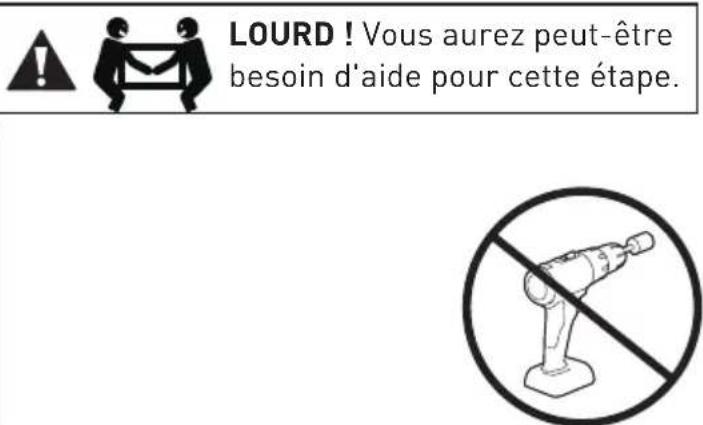
HEAVY! You may need assistance with this step.
natural_image
No crossed-out robot diagram without any text or symbolsGo to Step 3 on Page 23
Option B
For Drywall Installation
natural_image
Pure diagram of a structural support frame with two vertical supports and diagonal bracing (no text or symbols)
Tools Needed (Not Included)
Stud Finder AwlPencil Tape-Meansiere

WARNING:
- Drywall must be of sound construction with no water damage. If water damage occurs, remove the TV immediately.
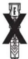
- If any of the nails encounter excessive resistance (metal objects), please stop and contact us.
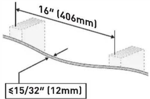
- DO NOT mount to patched areas, drywall seams, or uneven walls.
- DO NOT reuse the nails after removal. Do not use store-bought nails.
- DO NOT use lag screws A1 for wall anchors for this mounting option.
- Your TV MUST be centered on the wall plate.
A1
Lag Screw
A2
Wall Anchor
Find Studs and Mark Holes
natural_image
Simple line drawing of a mechanical setup with two bottles and a central component, enclosed in a circle (no text or symbols)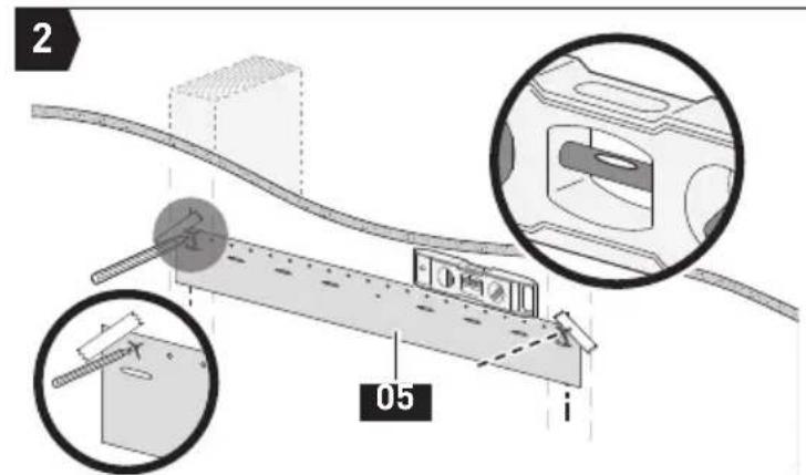
Mark 2 Hole Positions
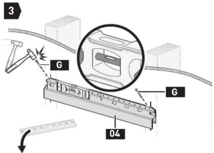
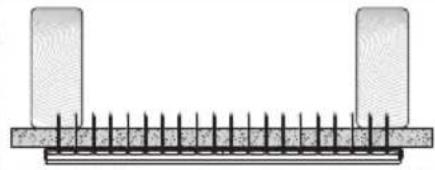
Install 1 Nail on Each Side
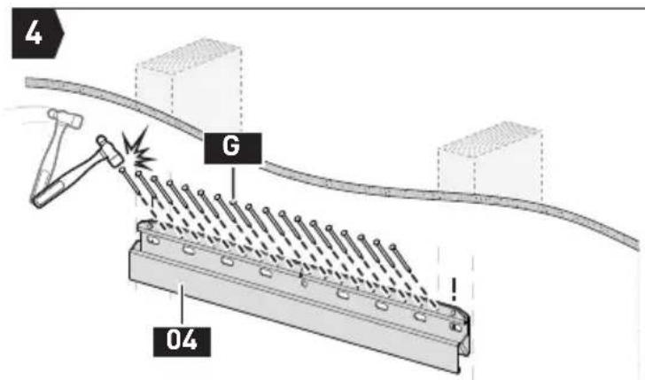
Install the Remaining 18 Nails
Go to Step 3 on Page 23
Option C
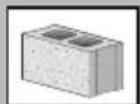
For Concrete and Concrete Block Wall Installation

Tools Needed (Not Included)
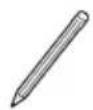
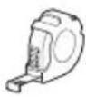
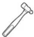
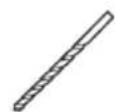
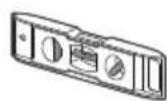
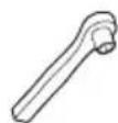
3/8" (10mm)
7/16" (11mm)
Concrete Drill BitHambev Electric Strike Re Wind Tape Me

WARNING:
- Avoid the risk of personal injury or property damage! Tighten the lag screws A1 only until they are pulled firmly against the wall plate (DO NOT overtighten). Do not use a drill; only use a socket wrench.
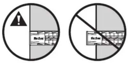
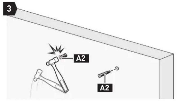
- Use wall anchors A2 for this mounting option.
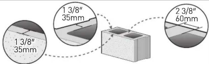
- Mount the wall plate directly on the concrete surface.
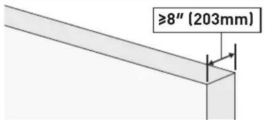
- Minimum concrete block size: 8" x 8" x 16" (203 x 203 x 406mm)
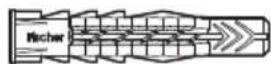
A2
Wall Anchor
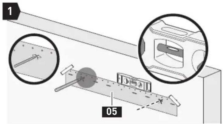
Mark 2 Hole Positions
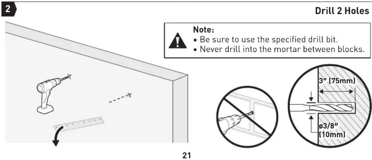
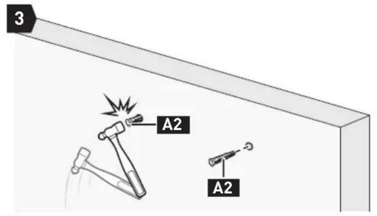
Tap Wall Anchors In
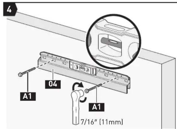
Secure the Wall Plate
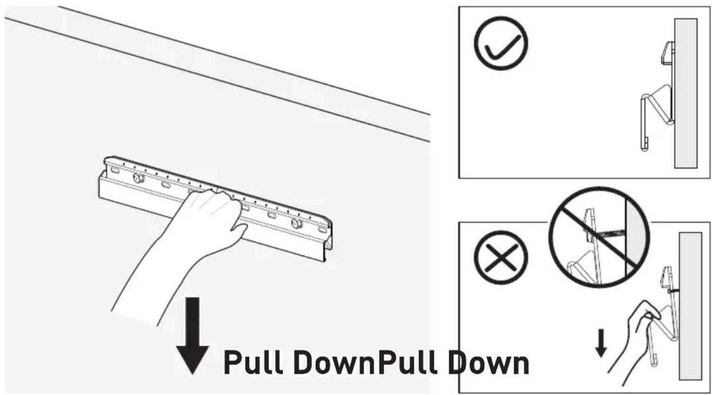
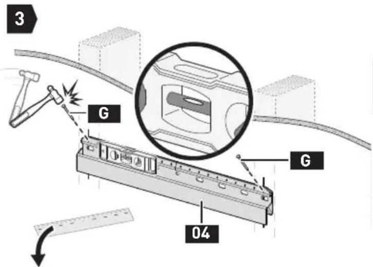
STEP 3 Verify Wall Plate is Firmly Mounted
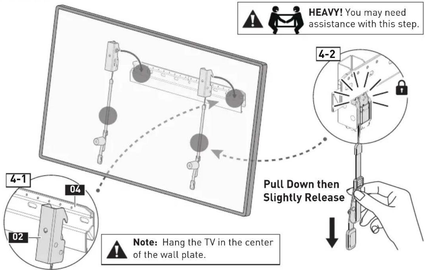
STEP 4 Hang the TV on the Wall Plate
STEP 5 Side-to-Side Shift
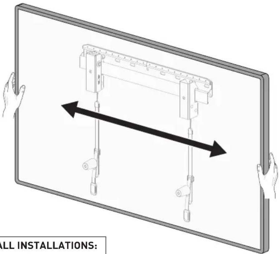

FOR DRYWALL INSTALLATIONS:
DO NOT slide the TV side-to-side.
STEP 6 Level Adjustment

Note: If your Phillips screwdriver is not long enough to turn the bolt L, please remove the TV to adjust the bolt L. After adjusting, hang up the TV and test to ensure the TV is level.

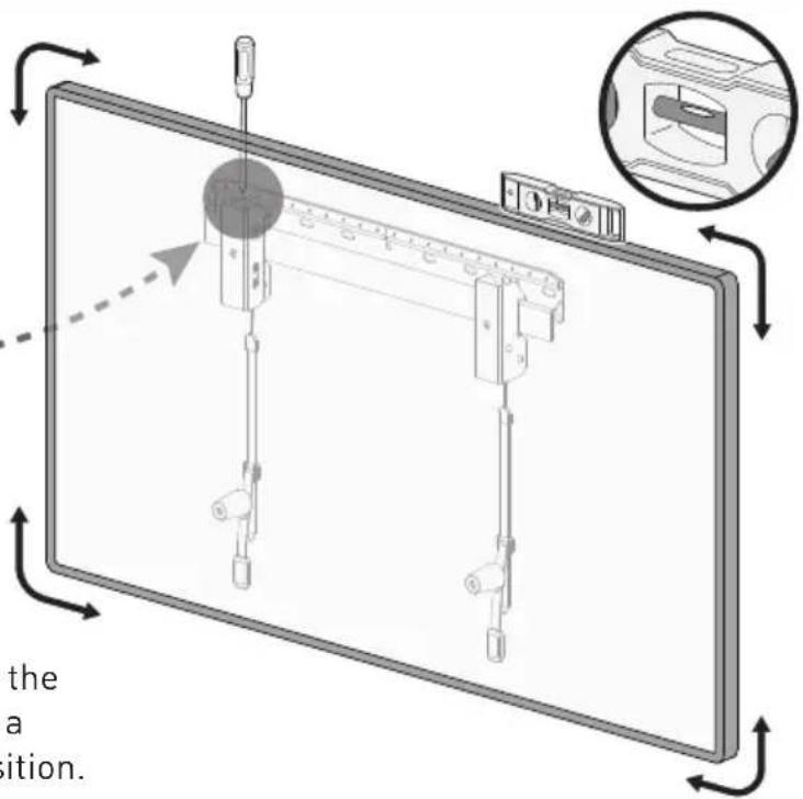
Turn the bolt L located at the top of the adjustable TV bracket 01 clockwise to raise the TV, or counterclockwise to lower the TV. Use a level to test and adjust the TV to the level position.
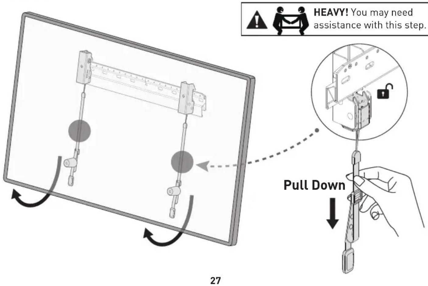
STEP 7 How to Remove the TV
AVANT DE COMMENCER, ASSUREZ-VOUS QUE CE SUPPORT EST COMPATIBLE
1
100 x 100mm 200 x 200mm 300 x 200mm 400 x 200mm
200 x 100mm 200 x 300mm 300 x 300mm 400 x 300mm
Maximum/Minimum :
400 x 400mm (15.7 x 15.7 po) / 100 x 100mm (3.9 x 3.9 po)
natural_image
Line drawing of a toothbrush and toothpaste device (no text or symbols)natural_image
Technical line drawing of a mechanical clamp or tool with no visible text or symbolsnatural_image
Close-up of a metallic screw with threaded shaft and flange (no text or symbols)natural_image
Cross-sectional diagram of a bolt inside a circular frame (no text or symbols)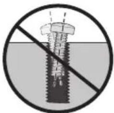
natural_image
Prohibition sign of a bolt with a diagonal line crossing through it, no text or symbols presentnatural_image
No sign depicting a drill bit crossed out by a diagonal line, enclosed in a circle (no text or symbols)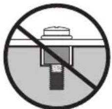
natural_image
Prohibition sign showing a battery plug with a stopper, crossed out by a diagonal line (no text or symbols)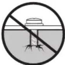
natural_image
Prohibition sign showing a prohibition symbol over a water surface with a floating object (no text or numbers present)Trop court Trop long
natural_image
Diagram of a computer monitor with ports and cables (no text or symbols)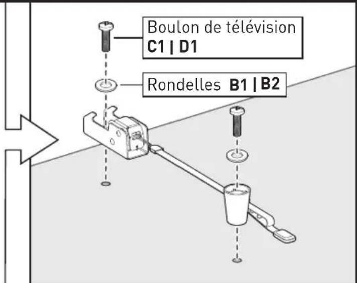
natural_image
Simple line drawing of a device with a lever and ports (no text or symbols)Téléviseur incurvé
natural_image
Simple line drawing of a mechanical device mounted on a curved platform with no text or symbolsnatural_image
Technical line drawing of a rectangular mechanical component with evenly spaced circular holes (no text or symbols)Plaque murale
04 x 1
natural_image
Simple line drawing of a mechanical setup with two cylindrical components and a central block, enclosed in a circle (no text or symbols)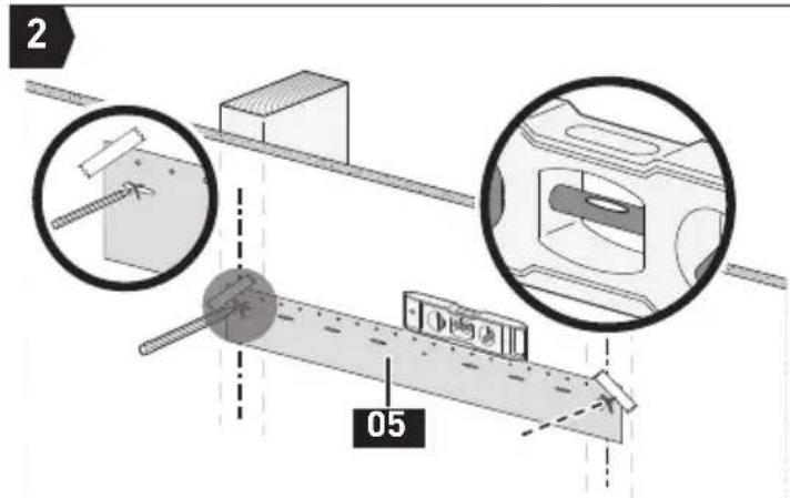
Marquez les positions des 2 trous

Fixer la plaque murale
natural_image
No crossed-out diagram of a robot holding a tool, enclosed in a circle (no text or symbols)natural_image
Pure structural diagram of a beam supported by two vertical supports (no text or symbols)
Crayon Mètre ruban
natural_image
Simple line drawing of a mechanical setup with two bottles and a central component, enclosed in a circle (no text or symbols)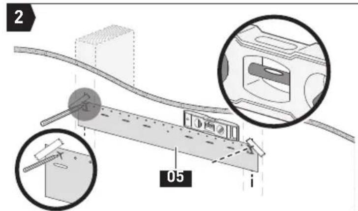
Marquez les positions des 2 trous
44
Fixer la plaque murale
100 x 100mm 200 x 200mm 300 x 200mm 400 x 200mm
200 x 100mm 200 x 300mm 300 x 300mm 400 x 300mm
Máximo/Mínimo: 300 x 400mm 400 x 400mm
400 x 400mm (15.7 x 15.7 pulg) / 100 x 100mm (3.9 x 3.9 pulg)
natural_image
Line drawing of a handheld electric toothbrush with a rectangular device (no text or symbols)Soporte de TV Ajustable
01 k 1

natural_image
Technical line drawing of a mechanical clamp or tool with no visible text or symbolsSoporte de TV
02×1
Amortiguador
03 x 2
M4/M5
Arandela
B1×4
M6/M8
Arandela
B2×4
L2.5mm
Separator
F1 k 8
L10mm
Separator
F2×4

L22mm
Separador
F3 k 4
M4
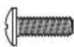
M4 x 12mm Pernos del televisor
C1×4
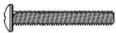
M4 x 30mm Pernos del televisor
C2×4
M6

M6 x 15mm Pernos del televisor
D1×4
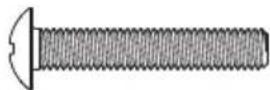
M6 x 35mm Pernos del televisor
D2×4
M8
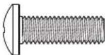
M8 x 25mm Pernos del televisor
E1×4
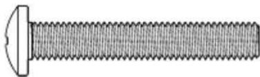
natural_image
Close-up illustration of a threaded bolt with a flat head (no text or symbols)M8 x 50mm Pernos del televisor
E2 k 4
natural_image
Prohibition sign showing a battery with a stopper crossed out, enclosed in a circle (no text or symbols)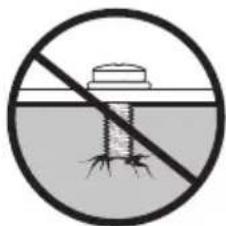
natural_image
Prohibition sign showing a circular absence of a water level with a prohibition symbol (no text or numbers present)Demasiado Largo

natural_image
Simple line drawing of a mechanical setup with a lever and weights (no text or symbols)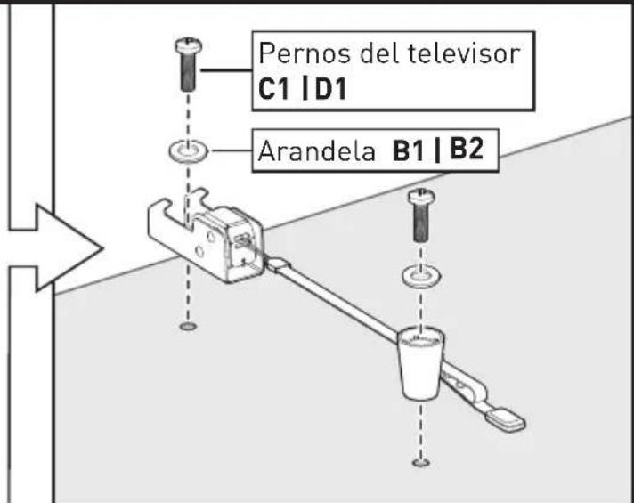
natural_image
Simple line drawing of a mechanical device with a lever and base, no text or symbols presentTelevisor curvo
natural_image
Simple line drawing of a mechanical device mounted on a curved platform with no text or symbolsnatural_image
Technical line drawing of a rectangular mechanical component with evenly spaced holes (no text or symbols)Placa de Pared
04×1

Plantilla de Placa de Pared
05 x 1
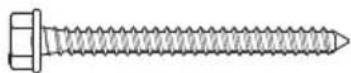
ST 1/4 x 2 3/4 pulg
Tornillo de retraso
A1×2

∅2.3 x 30mm
Clavo de Acero
G 20
¡PRECAUCIÓN!
natural_image
Simple line drawing of a mechanical setup with two bottles and a central component, enclosed in a circle (no text or symbols)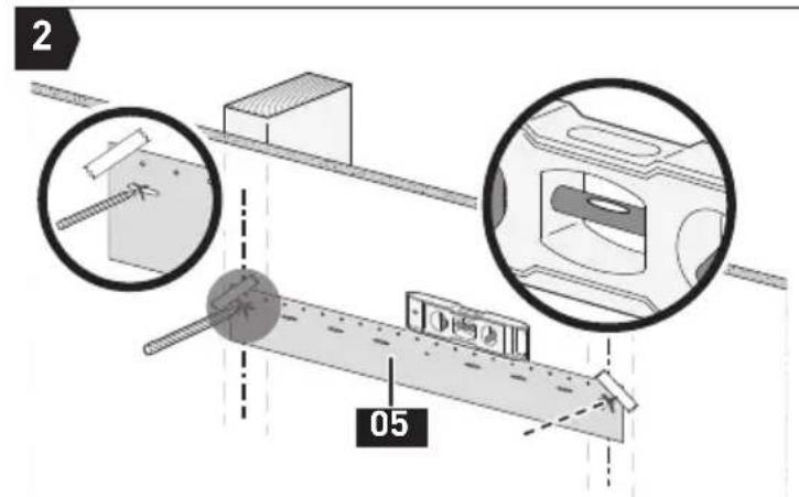
natural_image
Pure diagram of a structural support frame with two vertical posts and evenly spaced pins (no text or symbols)natural_image
Diagram of a mechanical setup with two jars and a central component, enclosed in a circle (no text or symbols)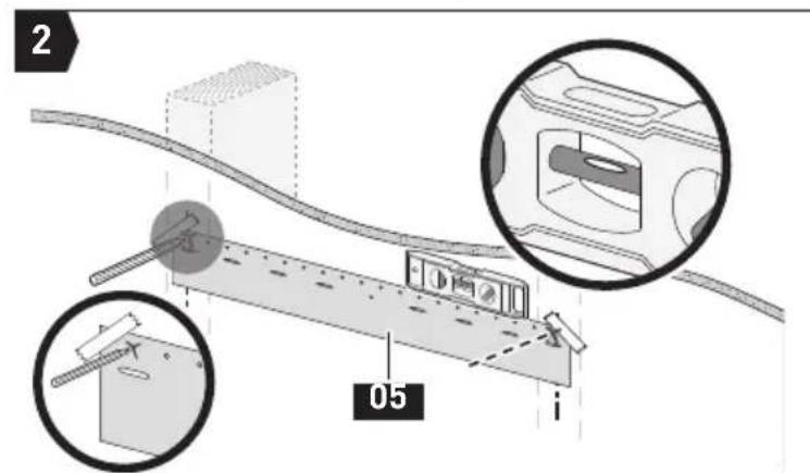
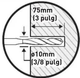
At ErgoAV, our goal is to provide the high-quality audio video solutions and product support that you need. If you have any questions, concerns, or feedback, please let us know!
natural_image
Technical line drawing of a mechanical coupling or assembly (no text or symbols)TV Mounts
natural_image
Simple line drawing of a vertical cylindrical structure with base and top (no text or symbols)Speaker Stands
natural_image
Technical line drawing of a Y-shaped mechanical assembly with two vertical arms and a central shaft (no text or symbols)Computer Monitor Mounts

ErgoAV

9501 Louisiana Ave N, #200, Brooklyn Park, MN 55445

(877) 419-7832
Mon-Fri 8am - 8pm (CST)

support@ergoav.com

www.ergoav.com
- Medium Fixed TV Mount Instruction Manual
- ERMLM3
- Thank you for choosing ErgoAV!
- BEFORE GETTING STARTED, LET'S MAKE SURE THIS MOUNT IS COMPATIBLE
- Compatible VESA Patterns:
- Wood Studs / Concrete / Concrete Block Walls:
- WARNING
- INSTALLATION
- Supplied Parts and Hardware for Step 1
- M4
- M6
- M8
- STEP 1 Attach the TV Brackets to Your TV
- 1-1 Select TV Bolts
- M4M4 M6M8M8M8
- 1-3 Secure the TV Brackets
- WARNING:
- Option A
- Option B
- Note:
- Supplied Parts and Hardware for Step 2
- CAUTION!
- STEP 2 Mount the Wall Plate on the Wall
- For Wood Stud Installation
- Tools Needed (Not Included)
- Option C
- STEP 3 Verify Wall Plate is Firmly Mounted
- STEP 5 Side-to-Side Shift
- STEP 6 Level Adjustment
- STEP 7 How to Remove the TV
- AVANT DE COMMENCER, ASSUREZ-VOUS QUE CE SUPPORT EST COMPATIBLE
- 1
- Maximum/Minimum :
- ¡PRECAUCIÓN!
Brand : ErgoAV
Model : ERMLM3-01B
Category : TV wall mount