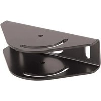
CPA395 - Fastening accessory Chief - Free user manual and instructions
Find the device manual for free CPA395 Chief in PDF.


| Product Type | Ceiling Angle Adapter |
| Brand | Chief |
| Model | CPA395 |
| Category | Mounting Accessory |
| Intended Use | Mounting projectors or screens to ceiling with adjustable angle |
| Maximum Load Capacity | 226.8 kg (500 lbs) |
| Material | Steel (estimated) |
| Compatibility | CPA UL extension columns, LCM2X2U, LCM3X1U, LCM3X2U, LCM3X3U video walls, etc. (see manual) |
| Ceiling Attachment | To double wood joists 51x102 mm (152.4 mm on center) with max 16 mm drywall |
| Required Mounting Screws | 2 lag bolts 3/8 x 2-1/2" (not included) |
| Adjustable Angle | Yes, via extension column |
| Installation Type | Mechanical ceiling attachment |
| Power | None (mechanical accessory) |
| Safety | Do not exceed max load; structure must support 5x total weight |
| Maintenance | Clean with a dry cloth (standard recommendation) |
| Outdoor Use | Not recommended |
| Certification of Compatible Components | UL (extension columns, video walls) |
| Country of Origin | Not specified |
| Warranty | Refer to manufacturer |
Frequently Asked Questions - CPA395 Chief
User questions about CPA395 Chief
0 question about this device. Answer the ones you know or ask your own.
Ask a new question about this device
Download the instructions for your Fastening accessory in PDF format for free! Find your manual CPA395 - Chief and take your electronic device back in hand. On this page are published all the documents necessary for the use of your device. CPA395 by Chief.
USER MANUAL CPA395 Chief
Milestone AV Technologies and its affiliated corporations and subsidiaries (collectively "Milestone"), intend to make this manual accurate and complete. However, Milestone makes no claim that the information contained herein covers all details, conditions or variations, nor does it provide for every possible contingency in connection with the installation or use of this product. The information contained in this document is subject to change without notice or obligation of any kind. Milestone makes no representation of warranty, expressed or implied, regarding the information contained herein. Milestone assumes no responsibility for accuracy, completeness or sufficiency of the information contained in this document.
Chief® is a registered trademark of Milestone AV Technologies. All rights reserved.
DEFINITIONS
WARNING: A WARNING alerts you to the possibility of serious injury or death if you do not follow the instructions.
CAUTION: A CAUTION alerts you to the possibility of damage or destruction of equipment if you do not follow the corresponding instructions
MOUNTING SYSTEM: A MOUNTING SYSTEM is the primary product designed by Chief® to mount the projector or display.
ACCESSORY: An ACCESSORY is any product designed by Chief® to complement the primary mounting system either by mounting any supporting components or enhancing the mounting capabilities of the primary mounting system.
COMPONENT: A COMPONENT is any secondary product to be mounted to an accessory, i.e. speakers, CPU's, cameras, tablets, additional displays.

IMPORTANT SAFETY INSTRUCTIONS!

WARNING: Failure to read, thoroughly understand, and follow all instructions can result in serious personal injury, damage to equipment, or voiding of factory warranty! It is the installer's responsibility to make sure all mounting systems/ accessories are properly assembled and installed using the instructions provided.

WARNING: Failure to provide adequate structural strength for this component can result in serious personal injury or damage to equipment! It is the installer's responsibility to make sure the structure to which this accessory is attached can support five times the combined weight of all equipment. Reinforce the structure as required before installing the accessory.

WARNING: Exceeding the weight capacity can result in serious personal injury or damage to equipment! It is the installer's responsibility to make sure the combined weight of all components located within the mounting system of the CPA395 does not exceed 500 lbs (226.8 kg).
- The weight capacity of the CPA395 may be LIMITED to the lowest weight capacity of any other mounting system or accessory located between the ceiling plate and the projector/display.

WARNING: Use this accessory only for its intended use as described in these instructions. Do not use attachments not recommended by the manufacturer.

WARNING: Never operate this accessory if it is damaged. Return the accessory to a service center for examination and repair.

WARNING: Do not use this product outdoors.
IMPORTANT ! : The CPA395 is designed to be mounted to double 2'' × 4'' wood stud cross bracing (6" on center) between two ceiling joists with a maximum drywall covering of 5/8''
IMPORTANT ! : The CPA395 must be attached to ceiling using two (minimum) 3/8 × 2 - 1/2 lag bolts (not included).
NOTE: The CPA395 may be used with the UL Listed CPA Extension Column series; the LCM2X2U, LCM2X2UP, LCM3X2U, LCM3X2UP and LCM3X3U ceiling mounted video walls; and the UL Listed LCM1U, LCM1UP, LCM2X1U, LCM2X1UP, LCM3X1U, LCM3X1UP, LCM5X1U, MCM1U, XCM1U, XCM7000, LCB1U, LCB1UP, LCB1X2U, LCB2X1U, LCB2X1UP, MCB1U, MCB1X2U, XCB1U, XCB7000, FCA3U and FCA4U (not included).
NOTE: The LCM2X2U, LCM2X2UP, LCM3X1U, LCM3X1UP, LCM3X2U, LCM3X2UP and LCM3X3U require 2 CPA395 ceiling plates (not included). The LCM5X1U requires 3 CPA395 ceiling plates (not included).
--SAVE THESE INSTRUCTIONS--
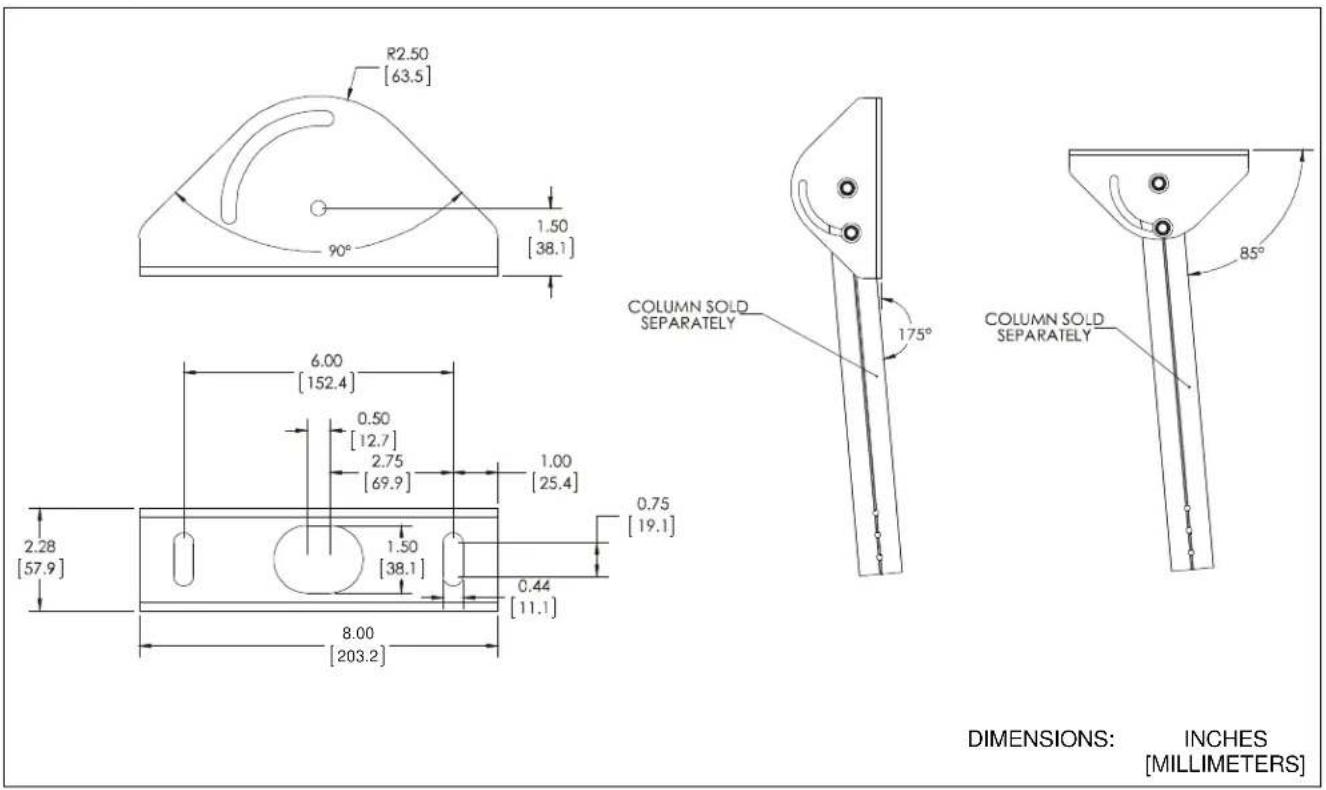
DIMENSIONS
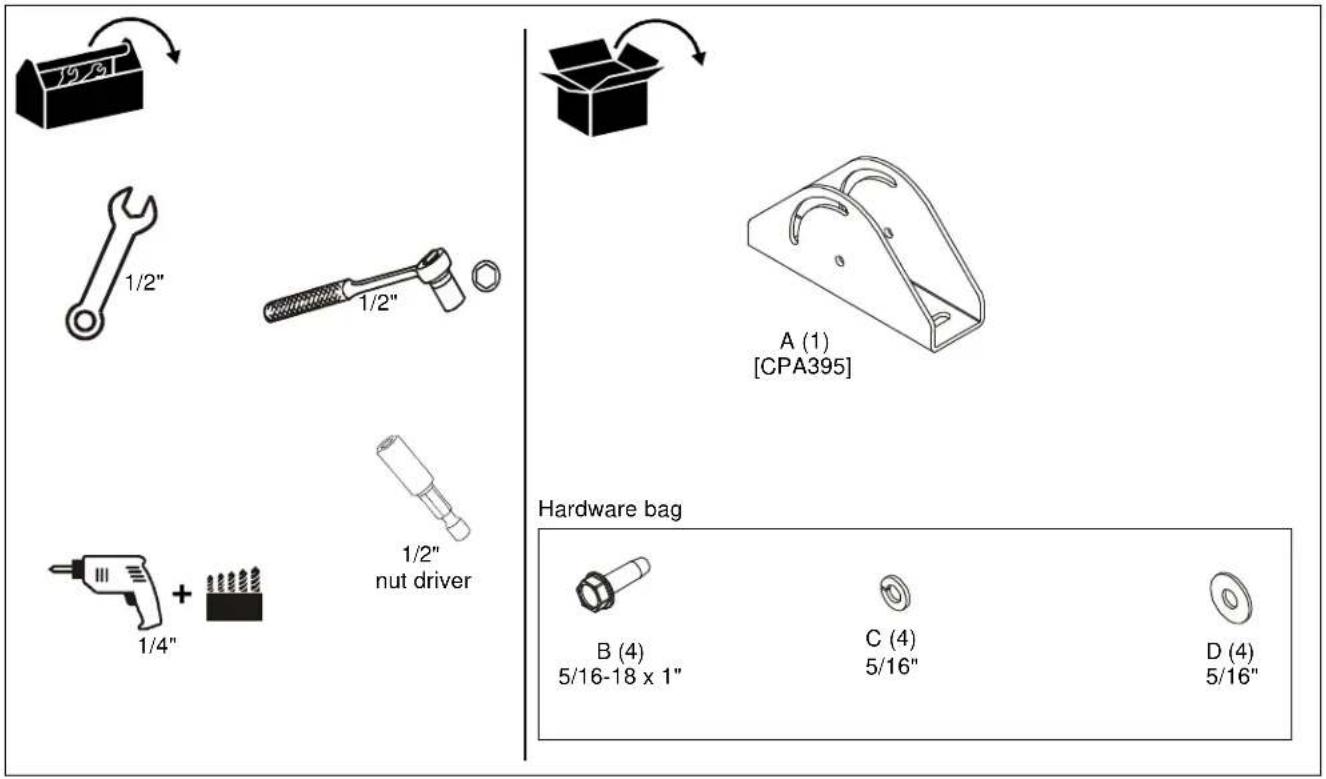
TOOLS / PARTS FOR INSTALLATION
ASSEMBLY AND INSTALLATION
IMPORTANT ! : The CPA395 is designed to be mounted to double 2'' × 4'' wood stud cross bracing (6" on center) between two ceiling joists with a maximum drywall covering of 5/8'' .

WARNING: IMPROPER INSTALLATION CAN LEAD TO LIFT FALLING CAUSING SEVERE PERSONAL INJURY OR DAMAGE TO EQUIPMENT! It is the installer's responsibility to make certain the structure to which the mount is being attached is capable of supporting five times the weight of the CPA mount and all attached equipment. Reinforce the structure as required before installing the mount.
NOTE: The following instructions assume a suitable mounting structure and surface exists prior to installation.
- Using CPA395 plate (A) as a template, mark locations of two pilot holes (See Figure 1). Ensure the marks are in the center of wood joists.
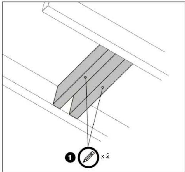
Figure 1
-
Drill 1/4'' diameter pilot holes into wood joists (See Figure 1). Ensure pilot holes are straight.
-
Install and tighten two 3/8'' × 2-1/2'' (minimum) Grade 2 lag screws (not included) through CPA395 (A), into wood joist (See Figure 2).
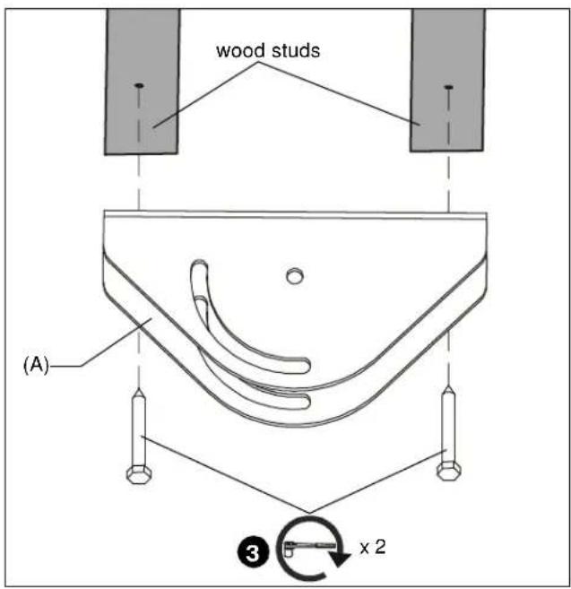
Figure 2
Installing Extension Column

WARNING: Exceeding the weight capacity can result in serious personal injury or damage to equipment! It is the installer's responsibility to make sure the combined weight of all components located within the mounting system of the CPA395 does not exceed 500 lbs (226.8 kg).
- Route cables through extension column (not included).
- Install UL Listed CPA Extension Column Series (not included) into CPA395.
NOTE: Installation of hex head self-tapping screws will be easier when screws are carefully aligned with holes in extension column, and a drill and nut driver is used. If a drill will NOT be used, a small amount of pressure will be needed to get the self-tapping screws started.
- Loosely install extension column (not included) to CPA395 using two 5 / 16 - 18 × 1 hex head self-tapping screws (B), two 5 / 16 split lock washers (C) and two 5 / 16 flat washers (D) through fastener hole in CPA395 into first hole on each side of extension column. (See Figure 3)
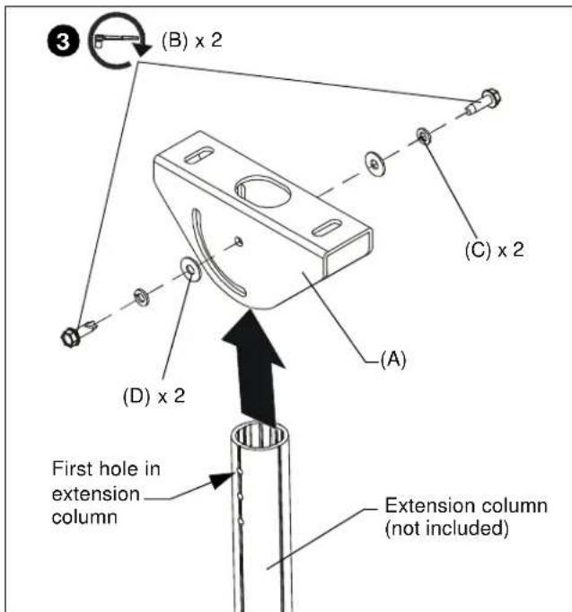
Figure 3
- Finish loosely securing extension column to CPA395 using two 5/16-18 x 1" hex head self-tapping screws (B), two 5/16" split lock washers (C) and two 5/16" flat washers (D) through adjustment slot in CPA395 and into third hole on extension column. (See Figure 4)

Figure 4
- Adjust extension column to desired angle. (See Figure 4)
- Tighten hardware installed in Steps 3 and 4.
- Complete installation following mount installation instructions.
CLAUSES DE NON-RESPONSABILITÉ


Brand : Chief
Model : CPA395
Category : Fastening accessory