Ventus Diesel 20 - Heating Sonnenkönig - Free user manual and instructions
Find the device manual for free Ventus Diesel 20 Sonnenkönig in PDF.


User questions about Ventus Diesel 20 Sonnenkönig
0 question about this device. Answer the ones you know or ask your own.
Ask a new question about this device
Download the instructions for your Heating in PDF format for free! Find your manual Ventus Diesel 20 - Sonnenkönig and take your electronic device back in hand. On this page are published all the documents necessary for the use of your device. Ventus Diesel 20 by Sonnenkönig.
USER MANUAL Ventus Diesel 20 Sonnenkönig
natural_image
Line drawing of a portable air purifier with cooling fan and control panel (no text or symbols)
FIRMA
Sonnenkönig of Switzerland
Olensbachstrasse 9-15
CH-9631 Ulisbach
Tel. Int. +41 58 611 60 00
Tel. Nat. 0848 870 850
Sonnenkönig of Switzerland
natural_image
Top-down view of a black industrial lamp with visible wiring and control buttons (no text or symbols)Tanköffnung
04 - INSTALLATION
natural_image
Line drawing of a portable air purifier with cooling fan and control panel (no text or symbols)
MAISON
Sonnenkönig of Switzerland
Olensbachstrasse 9-15
CH-9631 Ulisbach
Tel. Int. +41 58 611 60 00
Tel. Nat. 0848 870 850
Sonnenkönig of Switzerland
natural_image
Top-down view of a black industrial lamp or power supply unit with visible wiring and control buttons (no text or symbols)Modifications techniques
natural_image
Line drawing of a portable air purifier with cooling fan and control panel (no text or symbols)
DITTA
Sonnenkönig of Switzerland
Olensbachstrasse 9-15
CH-9631 Ulisbach
Tel. Int. +41 58 611 60 00
Tel. Nat. 0848 870 850
Sonnenkönig of Switzerland
natural_image
Top-down view of a black industrial lamp with visible wiring and control buttons (no text or symbols)Apertura del serbatoio
04 - INSTALLAZIONE
natural_image
Line drawing of a portable air purifier with cooling fan and control panel (no text or symbols)
COMPANY
Sonnenkönig of Switzerland
Olensbachstrasse 9-15
CH-9631 Ulisbach
Tel. Int. +41 58 611 60 00
Tel. Nat. 0848 870 850
Sonnenkönig of Switzerland
THIS PRODUCT IS NOT SUITABLE FOR
PRIMARY HEATING PURPOSES.
Item No. 20601012
Version 27.05.2021
01 - CONTENT
01 - CONTENT 38
02 - WARNING NOTICE 39
03 - TECHNICAL DETAILS 41
04 - INSTALLATION 42
05 - HOW TO USE 42
06 - CLEANING, CARE AND MAINTENANCE 43
07 - TROUBLE SHOOTING 45
08 - CONFORMITY / DISPOSAL 46
Please read and understand this manual completely before attempting to assemble, operate or install the product.
This manual contains important information about the assembly, operation and maintenance of this patio heater. General safety information is presented on these first pages and is also found throughout this manual. Retain this manual for future reference and to educate new users of this product. This manual should be read in conjunction with the labeling on the product. Safety precautions are essential when dealing with mechanical or diesel powered equipment. These precautions are required when using, storing and maintaining this item. Using this equipment with due respect and caution will reduce the possibility of personal injury or property damage.
EXPLOSION - FIRE HAZARD
- Store combustibles such as building materials, paper or cardboard, at a safe distance from the heater as recommended in the instructions.
- Provide adequate clearances from the heater.
- Never use the heater in areas that contain or may contain volatile or airborne combustibles or products such as gasoline, solvents, paint thinners, dust particles, or unknown chemicals.
- During operation, this product may be a source of ignition. Keep the area of the heater free of flammable materials such as gasoline, thinner, cleaning solvents, and other flammable gases and liquids. Do not use the heater in areas with high dust generation. Minimum distance of the heater from combustible materials: 3 meters from the sides and 2 meters from the top.
CARBON MONOXIDE - HAZARD
- This heater is a combustion appliance. All combustion appliances generate carbon monoxide (CO) during the combustion process. This product produces small, harmless amounts of CO when used and maintained in accordance with all warnings and instructions. Care should be taken not to block the flow of air to or from the heater.
- Carbon monoxide poisoning causes flu-like symptoms, watery eyes, headache, dizziness, fatigue, and possibly death. You cannot see or smell carbon monoxide. If you experience these symptoms while operating this unit, get fresh air immediately!
- Direct-fired heaters are intended for outdoor or well-ventilated indoor use. For indoor use, provide permanent ventilation openings of at least 500 cm ^2 , evenly distributed between floor and height.
- Never use indoors or in other unventilated or enclosed spaces.
• This heater consumes air (oxygen).
HAZARDOUS FUELS
- Never store combustibles near sources of intense heat, open flames, pilot lights, direct sunlight, other sources of ignition, or at temperatures above 49°C.
- Never install or remove combustibles while the heater is operating, near flames, pilot lights, other ignition sources, or when the heater is hot.
-
This heater is highly incandescent during use and may ignite flammable materials near the burner. Keep flammable materials at least 3 meters from the sides and 2 meters from the top. Keep gasoline and other flammable liquids and gases away from the heater.
-
Store combustibles outdoors or in a well-ventilated area out of the reach of children. Never store in an enclosed space (house, garage, etc.). If the heater is to be stored indoors, separate the fuels for outdoor storage.
- Do not store or use gasoline or other flammable gases and liquids near this or any other appliance. Do not store near this or any other appliance.
- It may be ignited by ignition sources such as matches, lighters, sparks or open flames of any kind, even if they are many feet away from the original appliance.
RISK OF BURNS
- Never leave the heater unattended when it is hot or in operation.
- Keep out of the reach of children.
- Certain materials or objects, if stored near the heater, will be exposed to radiant heat and could be seriously damaged.
SERVICE SAFETY
- The electrical system to which the device is connected must comply with the applicable legal regulations. The installation requires a residual current circuit breaker (RCD) in the electrical main distribution board.
- Unplug the unit from the mains before carrying out any maintenance work.
- Always check the power cord before using the unit. It must not be kinked, stretched, crushed or damaged in any way.
- If damaged, the power cord should only be replaced by qualified personnel.
- Keep all connections and fittings clean. Make sure the valve outlet is clean.
- During setup, check all connections and fittings for leaks using soapy water. Never use a flame.
- Use only as a heating device. Never modify in any way or use with any appliance.
- Warn children and adults of the dangers of high surface temperatures. Make sure they are a sufficient distance from these surfaces to avoid possible skin burns or clothing ignition.
• Always supervise young children when they are near the heater.
• Install all guards that have been removed to service the unit before returning it to service. - Installation and repair must be performed by qualified personnel only. Have the heater professionally inspected before use and once a year.
- More frequent cleaning may be required if necessary.
- Remove the heater from its carton. If the heater is damaged in any way, do not use it and contact your dealer.
VENTUS DIESEL 20
Heat output*: 20 kW
Air flow rate: 550 m³/h
Fuel type: Diesel - Kerosene
Fuel consumption: 1.65 kg/h
Fuel nozzle size: 0.50 gph
Voltage: AC220-240/50
Air pressure setting: 0.31 bar
Rated current: 0.9 A
Electrical power: 230 W
Fuse rating: T3.15A
Net weight:
Net weight: 10 kg
Length: 660 mm
Width: 260 mm
Height: 380 mm
Tank capacity: 12 l
Operating range: \~6 h
Standard accessories:
Fuel gauge
Handle
Ambient thermostat
Malfunction indicator light
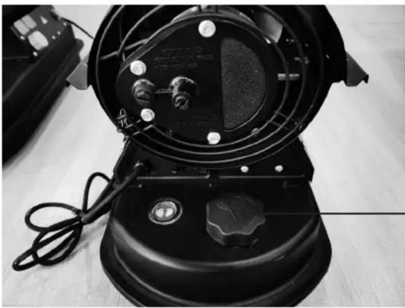
natural_image
Top-down view of a black industrial lamp with visible wiring and control buttons (no text or symbols)Tank opening
04 - INSTALLATION
- Place the heater on a flat, level, non-combustible, solid surface.
- Direct-fired heaters are intended for use outdoors or in well-ventilated indoor areas. For indoor use, provide permanent ventilation openings of at least 500 cm ^2 , evenly distributed between floor and height.
• Install the heater only in a normal, upright position. - Do not place the heater near walls, corners or low ceilings.
- Do not place the heater below an electrical outlet.
- Do not place the heater on top of moving vehicles or where it may tip over.
- Keep the heater away from flammable, combustible, explosive or corrosive materials.
- Keep the heater away from curtains or similar materials that could block the air inlet and outlet.
- Never block or restrict the air inlet and outlet for any reason.
- Keep the power cord away from heat sources, sharp edges, cutting and moving parts.
- Do not expose the heater directly to the weather or excessive moisture.
- Do not place the heater in a humid environment.
- Observe the general and special fire protection regulations that apply in all areas of application. In any case, maintain the following minimum safety distances from materials or objects in the vicinity of the heater:
Side: 0.6 m
Air inlet side: 1 m
Top side: 1.5 m
Hoit air outlet side: 3 m
Bottom: 0 m
- Floors and ceilings must be made of fireproof materials at the heater's place of use.
- Do not connect directly fired heaters to air ducts.
05 - HOW TO USE
Commissioning
- Fill the tank with clean fuel. Use only diesel or kerosene.
- The fuel gauge on the top of the tank allows you to check the fuel level
- Connect the plug of the power cord to a grounded power supply (AC220V-240V/50Hz).
The grounding is mandatory.
When the „Commissioning“ described above is completed, the power indicator lamp lights up. Slide the power switch to the „ON“ position.
When the temperature set with the thermostat controller is higher than the ambient temperature, the electrodes start sparking and after 7 seconds the heater starts. If the temperature set with the thermostat control is lower than the ambient temperature, turn the thermostat control to the desired temperature setting, the electrodes start to spark and after 7 seconds the heater starts.
Cold start
At low temperatures, keep the vent hole (see Fig. 1) closed with a finger during ignition to facilitate start-up.
Abnormal operation
In the event of a malfunction (flame failure, reduced airflow, poor combustion, etc.) the heater will stop and the operation indicator light will begin to flash.
Manual reset/restart
If the heater is in lockout mode, check and correct the cause of the lockout before turning the heater back on. To reset, turn the ON/OFF switch to 0 and then back to 1 after 30 seconds. In case of repeated malfunction, call the technical service. Turning the thermostat knob will NOT reset the heater.
Turn off
Move the switch to the „OFF“ (O) position. Unplug the heater if it will not be used for an extended period of time.
- Never disconnect the heater from the mains to stop it during operation.
- Do not cover the heater. Do not block the air inlet and outlet.
- The outlet of the heater is very hot during operation and after use. Do not touch it! Use personal protective equipment if necessary.
• Children should be supervised to ensure that they do not play with the unit. - The device is not intended to be used by persons (including children) with reduced physical, sensory or mental capabilities or lack of experience and knowledge.
- Unplug the device from the wall outlet before moving it. Never pull on the cord to unplug or move the unit.
- Do not leave the heater unattended when it is in use.
- Never use the unit with wet hands or when either the heater or the power cord is wet.
- If the supply cord is damaged, it must be replaced by the manufacturer, a service agent or a similarly qualified person.
06 - CLEANING, CARE AND MAINTENANCE
- Wipe the housing regularly with a soft sponge or cloth. For heavily soiled parts, use a sponge moistened with lukewarm water and a mild detergent, then dry with a clean cloth.
- Keep the air inlet and fan free of dust and dirt. Gently blow compressed air through the air inlet to clean the internal parts.
- Check the power cord regularly: if it is worn, torn or damaged, have it replaced by technical support.
- Clean the cables and plugs and dry them, then the cables can be stored in a plastic bag.
-
Before starting any maintenance work, switch off the heater, disconnect the power plug and allow it to cool down for at least 15 minutes.
-
Do not attempt to perform electrical repairs yourself. If the heater requires service or repair, contact a qualified technician.
- When cleaning, make sure that no water enters the unit.
- Do not open the housing to clean the internal parts. Do not spray water into the heater.
- Never use solvents, benzine, toluene and similar aggressive chemicals to clean the heater.
- If you want to stow the heater, let it cool down first. Allow the heater to dry and store it in a plastic bag. Place the heater in its original packaging and store it in a dry and well-ventilated place.
The following checks are recommended ONLY BY QUALIFIED PERSONNEL before each seasonal use:
Nozzle
Carefully unscrew the nozzle from the nozzle port. Blow compressed air through the nozzle orifice to clear it of debris. Replace the nozzle if necessary.
Air filter
Clean the air filter. Remove the filter end cover, wash the air intake filter with a light detergent, and dry it thoroughly before replacing it. Replace air outlet filter once per year.
Ignition electrodes
Clean, adjust, and replace ignition electrode if necessary.
Adjusting the compressor pressure
The compressor pressure is set at the factory and may only be checked and adjusted by qualified technicians. Tampering with the unit can be dangerous.
Remove the manometer cap. Connect a pressure gauge to the pressure measurement port on the rear cover. Turn heater on and read air pressure value. If necessary, adjust the pressure to the correct value by turning the adjustment screw (vent hole in the center of the adjustment screw) clockwise to increase the pressure and counterclockwise to decrease it:
Air pressure: 0.31 bar
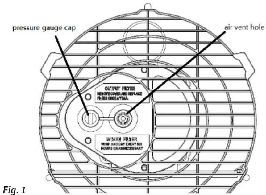
text_image
pressure gauge cap air vent hole OUTPUT FILTER REMOVE COVER AND REPLACE FILTER ONCEAYEAR. WIRAGE FILTER WASH AND DRY EVENT 500 HOURS OR AS NECESSARY Fig. 1Many problems can be solved by yourself, saving you repair costs. Try the following suggestions to see if the problem can be solved before contacting customer service.
| Problem Possible cause Remedy | ||
| Motor does not start. No power or low voltage. Check mains cable and voltage. | ||
| The power indicator lamp flashes. | Defective motor/capacitor. Check and replace if necessary. | |
| Unit lockout due to previous overheating. | Determine the cause of the overheating Switch off the unit. Check the air inlet and outlet. Wait a few minutes and restart the device. | |
| Engine runs, but heater does not ignite and shuts off after a short time. | Empty fuel tank, dirty or wrong fuel. Remove incorrect or contaminated fuel. Fill the tank with clean diesel or kerosene. | |
| The power indicator lamp flashes. | Fuel filter clogged. Clean or replace fuel filter. | |
| Air leaks in the oil line. Check hoses, tighten connections, replace if necessary. | ||
| Burner nozzle clogged. Clean compressed air nozzle, replace if necessary. | ||
| Fuel viscosity increased at low temperature. | Mix diesel with 10-20% kerosene. | |
| Flames come out of the exhaust gas outlet. | Insufficient air flow into the combustion chamber. | Check air intake, fan, engine. |
| Compressor pressure too high. Check air pressure, adjust if necessary. | ||
| Heater stops during operation. | The room temperature set on the room thermostat has been reached. | Normal operation. To start, turn the temperature control clockwise to a higher level. |
| Heater stops during operation. | Failure of the flame. Check and eliminate the cause(s) of the malfunction. | |
| Poor combustion. | ||
| The mains control lamp flashes. | Reduced air flow. | To reset, turn the on/off switch to 0 and then to 1. Call technical service if the problem persists. |
| Overheating. | ||
08 - CONFORMITY / DISPOSAL
Warranty
All products are checked from our company before the delivery. In case that there is a lack on your product, please contact the vendor. Please bring your proof of purchase for guarantees. Please save the packaging materials of the unit.
Disposal
Please remove the heater properly. You can bring the product to any specialist dealer fort he removal.
Technical changes
Technical changes in technique and design are possible.
CE declaration of Conformity
This device complies with the following standards
EMC EN 55014-1:2017
EN 55014-2:2015
EN IEC 61000-3-2:2019
EN 61000-3-3:2013 + A1:2019
LVD EN 60335-1:2012 + AC:2014 + A11:2014 + A13:2017 + A1:2019 + A2:2019 + A14:2019
EN 60335-2-102:2016
EN 62233:2008
ErP EN 13842
LVD 2014/35/EU
EMC 2014/30/EU
RoHS 2015/863/EU
ErP 2009/125/EU (2015/1188)
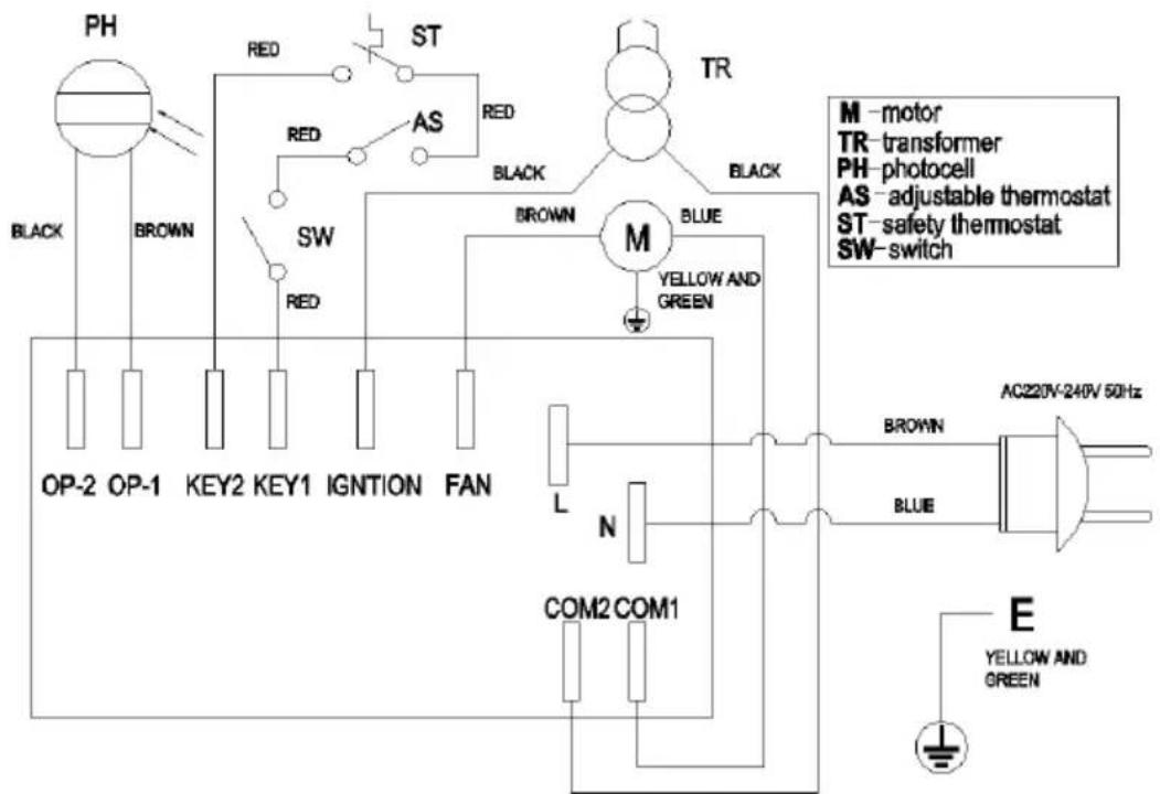
text_image
PH RED ST AS RED TR BLACK BROWN SW RED BROWN M BLUE YELLOW AND GREEN OP-2 OP-1 KEY2 KEY1 IGNTION FAN L N COM2 COM1 AC220V-240V 50Hz BROWN BLUE E YELLOW AND GREENAny modifications or repairs to the device must be carried out by a qualified person.
Since the development of the produced devices is constantly progressing, your product may differ minimally from the one described.
DISPOSAL INSTRUCTIONS FOR THE ELECTRICAL PART OF THE PRODUCT
In accordance with Article 26 of the Decree-Law of 14 March 2014 implementing Directive 2012/19/EC, and the Law of 31 March 2015 implementing Directive 2015/863/EU on the reduction of the use of hazardous substances in electrical and electronic equipment and on waste management.
The crossed-out dustbin symbol on the machine or packaging indicates that the waste generated at the end of its useful life must be collected separately from other waste. The user must therefore take the device to the appropriate collection points at the end of its service life. Sort electronic and electrical waste or send back to the retailer when purchasing new, equivalent devices in a one-to-one process. Appropriate separate collection for subsequent commissioning of the equipment to be recycled, treatment and environmentally sound disposal helps to avoid possible adverse effects on the environment and health, and promote the reuse and/or recycling of the materials to which they belong. Misuse of this product by the user will result in the application of the administrative penalties provided for in the applicable legislation. Batteries contained in the device must be disposed of separately in the appropriate containers for the collection of used batteries.
DISPOSAL OF BATTERIES AND ACCUMULATORS
In accordance with Legislative Decree 188 of 20 November 2008 implementing Directive 2006/66/EC on batteries, accumulators and related waste, the symbol of the crossed-out waste bin on the battery indicates that the disposal of used batteries is prohibited in household waste.
Single-use and rechargeable batteries contain substances that are highly polluting for the environment. The user is obliged to dispose of used batteries at collection points in the municipality or in appropriate containers. This service is free. In this way, legal requirements are adhered to and the environment protected. The symbols identifying hazardous materials that may be present in single-use and rechargeable batteries are as follows: Hg = Mercury, Cd = Cadmium, Pb = Lead.
NL
NEDERLANDS
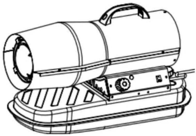
VENTUS DIESEL 20
HETELUCHTBLAZER
natural_image
Line drawing of a portable air purifier with cooling fan and control panel (no text or symbols)
BEDRIJF
Sonnenkönig of Switzerland
Olensbachstrasse 9-15
CH-9631 Ulisbach
Tel. Int. +41 58 611 60 00
Tel. Nat. 0848 870 850
Sonnenkönig of Switzerland
| Table for information requirements for VENTUS DIESEL 20 | |||||||
| Indirect heating functionality: [no] | |||||||
| Direct heat output: 20 (kW) | |||||||
| Indirect heat output: N/A (kW) | |||||||
| Fuel | Space heating emissions (*) | ||||||
| NOx | |||||||
| Select fuel type | [liquid] | Kerosene | 79 [mg/ kWh Input] (GCV) | ||||
| Item | Symbol | Value | Unit | Item | Symbol | Value | Unit |
| Heat output Useful efficiency (NCV) | |||||||
| Nominal heat output P | nom 20 kW | Useful efficiency at nominal heat output | η_n,nom | 100 | % | ||
| Minimum heat output (indicative) | Pmin | N/A | kW | Useful efficiency at minimum heat output (indicative) | η_n,min | N/A | % |
| Auxiliary electricity consumption | Type of heat output/room temperature control (select one) | ||||||
| At nominal heat output | elmax | 0.002 | kW | Single stage heat output and no room temperature control | [no] | ||
| At minimum heat output | elmin | N/A | kW | Two or more manual stages, no room temperature control | [no] | ||
| In standby mode | elSB | N/A W | With mechanic thermostat room temperature control | [no] | |||
| With electronic room temperature control | [yes] | ||||||
| Electronic room temperature control plus day timer | [no] | ||||||
| Electronic room temperature control plus week timer | [no] | ||||||
| Other control options (multiple selections possible) | |||||||
| Room temperature control, with presence detection | [no] | ||||||
| Room temperature control, with open window detection | [no] | ||||||
| With distance control option | [no] | ||||||
| With adaptive start control | [no] | ||||||
| With working time limitation | [no] | ||||||
| With black bulb sensor | [no] | ||||||
| Permanent pilot flame power | |||||||
| Pilot flame power requirement (if appli-cable) | Ppilot | 0 | kW | ||||
| Contact details | Sonnenkönig of Switzerland, Olensbachstrasse 9-15, CH-9631 Ulisbach, Switzerland | ||||||
| (*) NOx = nitrogen oxides | |||||||