R4DW-X S - Stapler HILTI - Free user manual and instructions
Find the device manual for free R4DW-X S HILTI in PDF.

| Product type | Pneumatic stapler |
| Brand | Hilti |
| Model | R4DW-X S |
| Height | approx. 515 mm (20 1/4 in) |
| Length | approx. 450 mm (17 3/4 in) |
| Width | approx. 100 mm (4 in) |
| Weight | 5.4 kg (11.9 lb) |
| Power source | Compressed air |
| Maximum operating pressure | 175 PSI (12 bar) |
| Magazine capacity | 20 nails |
| Air consumption | approx. 6.5 liters per fastener |
| Main features | Single shot discharge, pressure adjustment, cold weather operation |
| Maintenance and cleaning | Daily lubrication with Hilti ATL oil, cleaning with kerosene, greasing rings with Hilti special grease no. 12423 |
| Safety | Never exceed 175 PSI, wear safety glasses/ear protection/helmet, disconnect air before maintenance, do not point at people |
| Spare parts and repairability | Use only original Hilti parts, Hilti after-sales service (1-800-663-4458) |
| Warranty | Manufacturer's warranty against material and manufacturing defects for the life of the tool |
| General information | Operating instructions available online, 36 pages, multilingual (FR, DE, EN, ES) |
Frequently Asked Questions - R4DW-X S HILTI
User questions about R4DW-X S HILTI
0 question about this device. Answer the ones you know or ask your own.
Ask a new question about this device
Download the instructions for your Stapler in PDF format for free! Find your manual R4DW-X S - HILTI and take your electronic device back in hand. On this page are published all the documents necessary for the use of your device. R4DW-X S by HILTI.
USER MANUAL R4DW-X S HILTI
natural_image
Close-up of a hand operating a mechanical device with a tool handle (no visible text or symbols)a) b) c)
natural_image
Close-up of hands operating a mechanical device with tools (no visible text or symbols)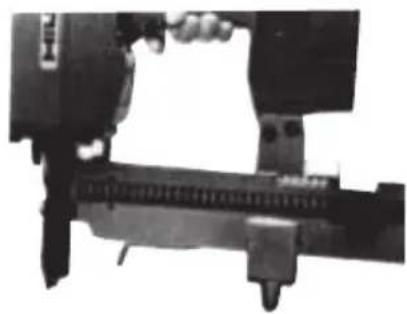
natural_image
Close-up of a mechanical assembly with no visible text or symbols2
It is essential that the operating instructions are read before the tool is operated for the first time.
Alwayskeeptheseoperatinginstructions togetherwiththetool.
Ensure that the operating instructions are with the tool when it is given to other persons.
Contents Page
| 1. Safety Rules 1 | |
| 2. Technical Data for the R4DW-X S 2 | |
| 3. Tool Set-Up and Operation 2 | |
| 4. Loading the magazine 2 | |
| 5. Normal operation 2 | |
| 6. Cold weather (40°F or colder) operation | 3 |
| 7. Preventive Maintenance 3 | |
| 8. Replacement Parts and Repair Service | 3 |
| 9. R4DW-X S Troubleshooting Guide | 4 |
| 10. Instructions for disassembly of R4DW-X S — Internal working parts | 5 |
| 11. Instructions for reassembly of the R4DW-X S | 6 |
| 12. R4DW-X S Spare Parts | 7 |
| 13. Manufacturer's warranty – tools | 8 |
1. Safety Rules
ALWAYS follow maintenance and operation instructions contained in this manual.
NEVER exceed the maximum rated pressure (175 PSI or 12 bar) for your tool.
NEVER leave a loaded tool unattended while it is connected to air.
NEVER remove or tamper with the operation of the trigger or the safety return spring on your air tool. Check the safety yoke and trigger daily to ensure they operate freely and correctly. DO NOT use a tool that is not operating properly. Have the tool serviced periodically by a qualified technician to check for worn or damaged parts, and to keep the internal components clean.
NEVER load the tool until you are ready to use it. DO NOT depress the trigger during loading.
NEVER point the tool at yourself or anyone else.
AVOID unfavorable body positions. Work from a secure stance and stay in balance at all times.
NEVER carry the tool with the trigger depressed.
DO NOT use oxygen, combustible gases or high pressure compressed gas tanks as the air supply for the tool.
ALWAYS use authentic Hilti R4DW-X S fasteners and parts in your tool.
SAFETY equipment such as safety glasses, hearing protection and hard hat should ALWAYS be worn by the operator and bystanders when the tool is in use.
ALWAYS disconnect the air supply and empty the magazine before:
●work breaks
●changing parts
● servicing or inspecting tools or clearing a jammed fastener
● storing tool at the end of the day
● when leaving the tool unattended
NEVER install female couplers on the tool since they may store air in the tool even after the air supply is disconnected.
ALWAYS connect air supply to the tool before loading fasteners.
2. Technical Data for the R4DW-X S
| Tool Height (with top handle) approx. 20 | ^1/_4 " (515 mm) |
| Tool Length approx. 17 | ^3/_4 " (450 mm) |
| Tool Width approx. 4" (100 mm) | |
| Tool Weight 11.9 pounds (5.4 kg) | |
| Magazine Capacity 20 nails | |
| Max. Operating Pressure 175 PSI (12 bar) | |
| Air Consumption | approx. 0.23 cubic ft/fastener (6.5 l) |
3. Tool Set-Up and Operation
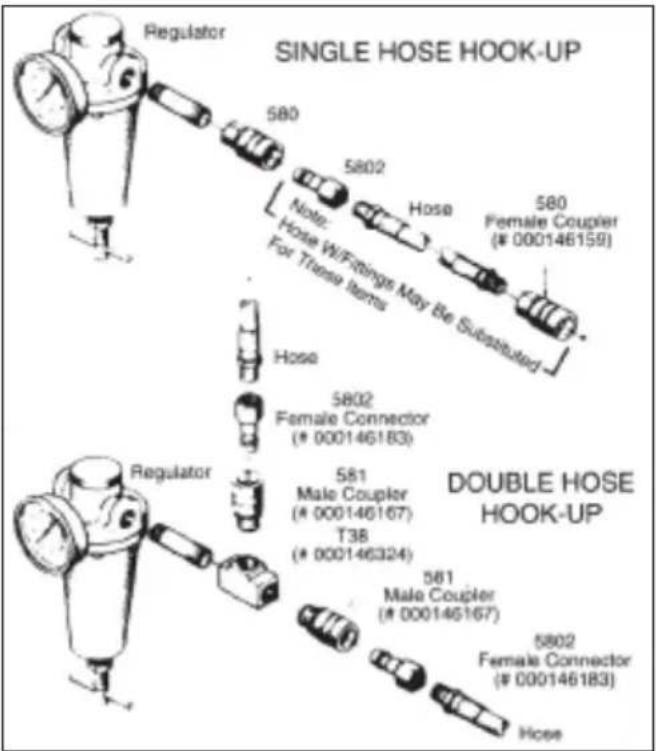
3.1 SET-UP
Connect the air line to the regulator (see diagram to the right). Wrap all male threaded connections with "Teflon" tape prior to assembly to prevent leakage.
NOTE: Make sure that couplers are attached only to the compressor side of the air supply system, and all components are rated for the tool operating pressure.
3.2 Lubricate the tool
Use Hilti ATL (Air Tool Lubricant) or an equivalent lightweight acid-free, non-detergent oil (viscosity 3–4 Engler/20°C; aniline point 60°C).
During normal use, squirt 2–3 drops of oil daily into the air connector fitting on the tool.
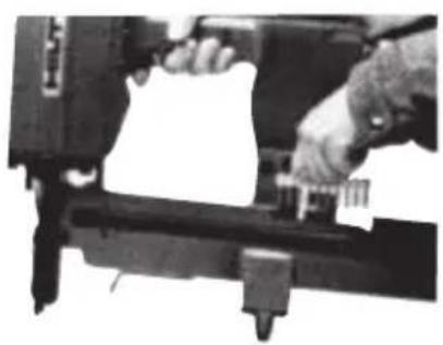
4. Loading the magazine
(Always connect air supply to the tool before loading fasteners into magazine)
- Pull the pusher fully back wards until it is held in place by the pusher latch pin. (1-a)
-
Insert the strips of nails into the magazine and slide all the way forward. The nail strips should be inserted parallel to the magazine. (1-b)
-
Holding the pusher firmly, release it from the magazine catch and guide the pusher forward until it rests against the fasteners. Do not allow the pusher to strike the nail strip with full spring force as it can break up the collation that holds the nails together and cause jamming. (There is a built-in firing detent on the pusher that will prevent the tool from operating when the magazine is empty.) (1-c)
5. Normal operation
5.1 Adjust the air pressure
To the minimum required to drive the fastener, making sure never to exceed the maximum rated pressure for the tool (175 PSI).
5.2 Single fire operation
For precision fastenings, place the tool nose in the correct position and depress the safety yoke, then quickly pull and release the trigger. Repeat in a new location.
6. Cold weather (40°F or colder) operation
6.1 Warm up the tool
- If possible, store the tool overnight in a warm place.
- OR - setthetoolinawarmspotsuchas vehicle. NEVER expose the tool to an open flame.
- OR - Free-fire the tool (shoot without fasteners) at a pressure of 25 PSI to gradually warm up moving parts. NEVER free-fire the tool at high pressure.
6.2 Use a suitable lubricant
- "Kilfrost", a special lubricant that prevents moisture a wualdum and ice formation in cold weather, is available from your Hilti Representative.
en
7. Preventive Maintenance
The maintenance schedule required for your tool will vary with such factors as amount of use, storage conditions, air quality, humidity, and outside temperature. It is important for each user to establish and maintain a schedule based upon his usage.
-CAUTION- when cleaning:
Never use grease for the maintenance/lubrication of parts of the tool. This may lead to malfunctions. Use only Hilti lubricant spray or a product of comparable quality.
The residues deposited inside tools contain substances that may be injurious to your health:
- Do not inhale any dust or dirt while cleaning.
- Keep the dust or dirt away from foodstuffs.
– Wash your hands after cleaning the tool.
7.1 Cleaning
Disassemble the tool monthly and wash away sludge and dirt with kerosene to keep the tool operating efficiently; be certain to re-lubricate the 0-rings with special 0-ring lubricant (Hilti item no 12423) and re-oil the tool after each cleaning. NEVER use Diesel fuel or flammable cleaning solvents to clean the tool.
7.2 Daily lubrication
Follow the “Lubricate The Tool” instructions under Tool Set-up and Operation.
7.3 Bumper
Check for surface deterioration monthly. Discoloration is first sign of wear.
7.4 Inspection
Daily inspect screws and nuts on tool. Tighten any which may have loosened during operation.
7.5 0-ring
Check monthly for deterioration. If an 0-ring appears worn, replace it, along with the others in that assembly. Lubricate the replacement 0-rings with special 0-ring grease (Hilti item 12423) before reassembling the tool.
7.6 Safety yoke
Inspect daily to ensure that the safety mechanism is operating properly and that it is not binding from wood particles, sawdust and other debris.
7.7 Compressor
Maintain in accordance with manufacturer's recommendations. NEVER operate a compressor at pressures or speeds in excess of those recommended by the manufacturer.
7.8 Compressor air filters
Clean or replace compressor air filter cartridge regularly.
7.9 Eliminate air line moisture
By draining the compressor storage tank daily in those areas with high relative humidity.
By using an air line moisture filter and emptying it frequently.
By avoiding the use of an excessive number of connections in long air lines.
8. Replacement Parts and Repair Service
Your Hilti air tool is precision engineered for safety and durability. NEVER attempt to modify parts, since this can compromise the built-in safety and shorten the life of the tool.
When servicing, use only identical Hilti replacement parts. Replacement parts shown on the parts list are available through your local Hilti representative or by calling Customer Service at 1-800-879-8000.
Hilti operates a nationwide network of Repair Centers, and rapid service is a hallmark of the Hilti system. If your tool requires service or warranty repairs, contact your local Hilti Representative or Customer Service at 1-800-879-8000.
8.1 Tools needed for R4DW-X S Service
- 4 mm Allen Wrench
-
5 mm Allen Wrench
-
6 mm Allen Wrench
●10 mm Open End Wrench
●17 mm Open End Wrench
-2 mm Pin Punch
●Hammer
●Flat blade screw driver
● Hilti 0-ring grease (Item no 12423)
●0-ring Pick or Scribe
8.2 Troubleshooting
(Check part numbers against exploded parts drawings)
If a problem arises, follow these steps before servicing the tool:
- Make sure the compressor is operating at the correct pressure and all valves to the supply line are open.
- Make sure moisture is not interfering with the free flow of air. To do this, drain the compressor storage
tank and moisture filter daily. (Storage tank drains are usually located on the bottom of the tank(s). The moisture filter is generally located next to the regulator.)
- Check the regulator(s) for the correct air pressure and that all valves to the supply line are open.
- Check the fittings and hoses for kinks, leaks, or blockages and ensure they are 38 " diameter in size for best operation.
- If a tool known to be in working condition is available, connect it in place of the malfunctioning tool and test it to see if the problem disappears. If the problem continues, then the problem is probably not in the tool.
IMPORTANT NOTE: If servicing a tool is required, ALWAYS disconnect the tool from the air supply and empty the magazine before attempting to service the tool.
- R4DW-X S Troubleshooting Guide
| Symptom Possible Cause Remedy | ||
| Fastener Skipping | Air Pressure too low | Increase air pressure to the minimum required to eliminate skipping — Max 175 PSI |
| Incorrect lubrication | Refer to setup instructions for proper cleaning and lubrication | |
| Obstruction in nosepiece (#8) | Clear obstruction using nylon brush or compressed airContact your Hilti Representative | |
| Pusher (#47) not moving freely or nails jamming in magazine (#48) | Check for easy movement. Clean or replace magazine and/or pusher as necessary | |
| Scroll spring (#51) damaged | Replace scroll spring. Contact your Hilti Representative | |
| Driver/Blade Assy (#16) bent or damaged | Replace Driver/Blade Assy (#16) | |
| Piston Driver 0-ring (#17) worn | Replace 0-ring (#17) Kit #12657 | |
| Bumper (#12) worn or damaged | Replace bumper as necessary | |
| Fastener Standoff | Air pressure too low | Increase pressure to minimum necessary to drive the fastener — Max.175 PSI |
| Compressor too small | Consult your local Hilti Representative | |
| Fastener Standoff | Defective regulator or gauge | Repair or replace as necessary |
| Incorrect lubrication | Refer to set-up instructions for proper cleaning and lubrication | |
| Incorrect nail | Consult your local Hilti Representative | |
| Driver blade broken | Replace Driver/Blade Assy (#16) | |
| Piston Driver 0-ring (#17) worn or damaged | Replace 0-ring (#17) Kit #12657 | |
| Fastener Overdrive | Air pressure too high | Decrease to minimum pressure required to just sink the fastener |
| Incorrect nail | Consult your local Hilti Representative | |
| Bumper (#12) worn | Check and replace as necessary | |
Air Leaks
| — at Valve Cap Assy (#23) | Valve ring 0-ring (#24) damaged or worn | Fit 0/H Kit #12552 |
| Valve Cap 0-ring (#22) and/or (#18) damaged or worn | Fit 0/H Kit #12553 | |
| —from trigger valve bushing assy (#35) damaged | 0-ring (#36) and/or (#38) worn or | Fit 0/H Kit #12557 |
| —at Trigger Valve Piston (#37) | 0-rings (#38) damaged or worn | Replace 0-rings. Fit 0/H Kit #12557 |
| — between grip (#40) and grip cover (#45) Screws | Gaskets damaged(#58) loose Tighten screws | Replace gaskets (#42) |
| —at Safety Valve (#54) Piston Assy | 0-rings (#55) damaged or worn | Fit 0/H Kit #12652 |
| Trigger valve body 0-rings damaged | Fit 0/H Kit #12554 | |
| Trigger valve body defective (#56) | Replace trigger valve body assy. | |
| —at nosepiece (#8) nail exit | Damaged bumper (#12) | Replace bumper (#12) as necessary |
| 0-ring (#14) damaged or worn | Replace 0-ring. Fit 0/H Kit #12552 | |
| 0-rings (#18, #19) damaged or worn | Replace 0-ring. Fit 0/H Kit #12552 | |
| Tool will not fire | Air pressure too low | Check air source, regulator setting gauges, hoses, fittings, etc. |
| Safety yoke (#1) stuck in down position | Check for dirt or obstructions Replace safety if deformed | |
| — Driver Blade Assy (#16) stuck down | Nails jammed in nosepiece (#8) | Clear jammed nailInspect Driver Blade and Nosepiece |
| Bent Driver Blade | Replace Driver Blade Assy (#16) | |
| 0-rings (#17) damaged or worn | Fit OH Kit #12657 | |
| Bumper (#12) severely damaged | Replace bumper | |
| Defective trigger valve body (#56) | Replace trigger valve body assy |
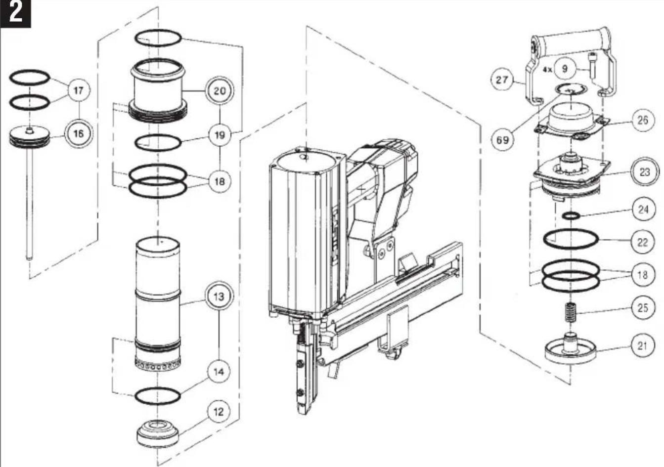
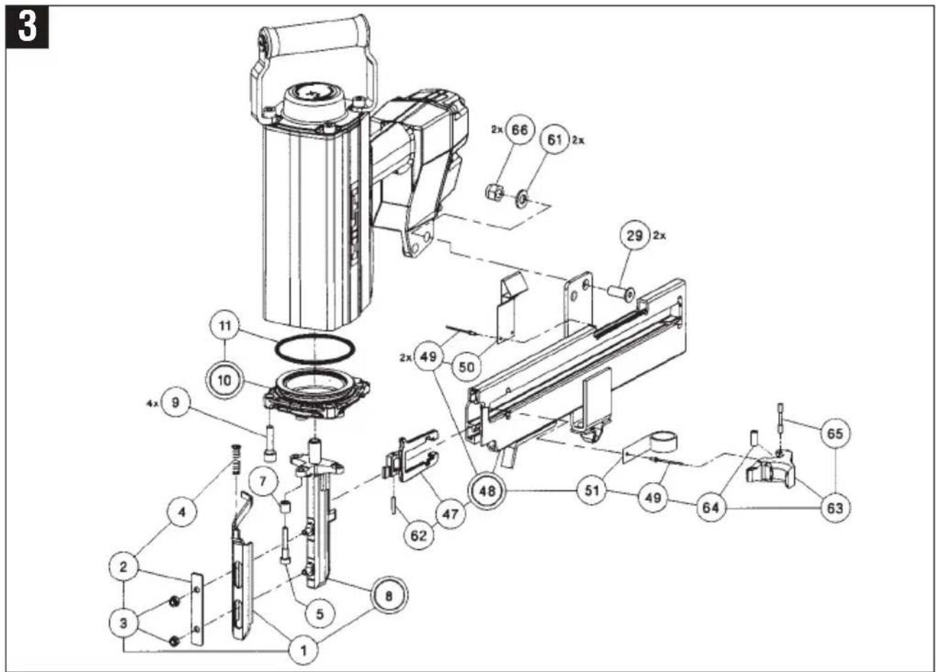
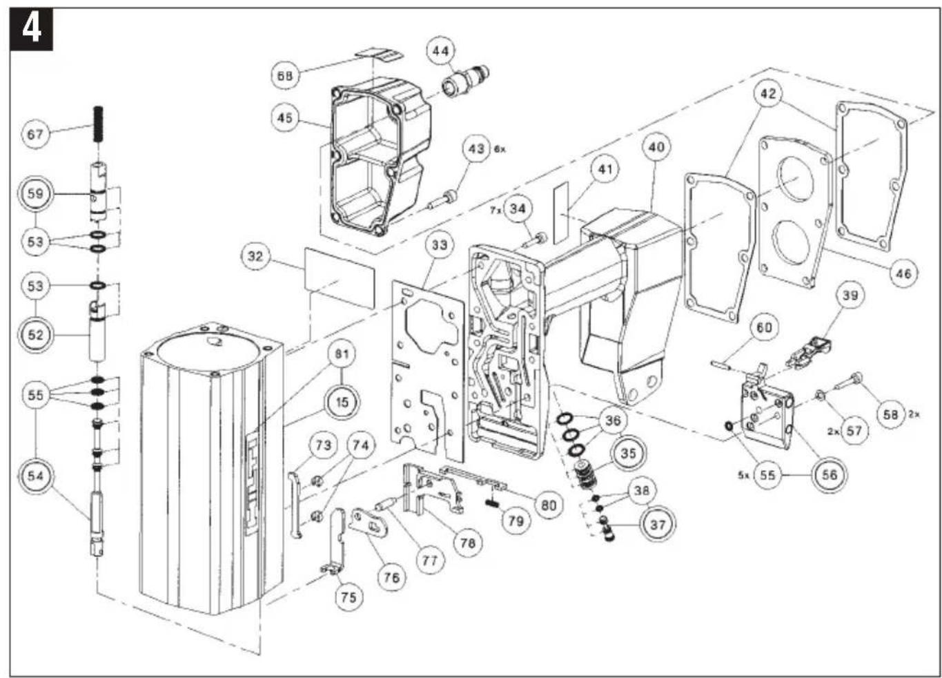
10. Instructions for disassembly of R4DW-X S — Internal working parts
(Use with Exploded View Drawings (2-4) and Parts list)
NOTE: Before starting on the disassembly of the tool, disconnect the tool from the air supply and remove all fasteners from the magazine assembly. If handle grip (40), plate (46), flange (10), and valve bushings (52, 59) require service, contact your Hilti Representative.
10.1 Magazine assembly (48)
Release 2 nuts (66) using a 17 mm open end wrench and 5 mm Allen wrench. Remove hex socket screws (29) and washers (61). Position pusher (47) in forward position and remove magazine assembly (48) from nose-piece (8).
10.2 Pusher (47) and grip (63)
Using a 2 mm pin punch, drive out spring pin (62). Remove pusher (47) from magazine (48) by sliding for-
ward and away from magazine. Pull back grip (63) slightly, align grip pin (65) with detents in magazine and tilt back portion of grip up. Once grip pin (65) is clear of magazine, tilt the grip (63) up and forward to clear the scroll spring. If necessary, tap grip pin (65) out of bushing (64) and grip (63). If the scroll spring (51) requires replacement, contact your local Hilti Representative.
10.3 Safety yoke (1)
Remove 2 hex locknuts (3) using a 10 mm open end wrench and take off guide plate (2). Remove the safety return spring (4). Remove the hex socket screw (5) closest to Valve Piston Assembly (54) using a 5 mm Allen wrench. It is not necessary to remove the nosepiece (8). Slide out safety yoke (1) from Safety Valve Piston Assembly (54).
10.4 Safety valve piston assembly
(54): (Safety yoke already removed, see 10.3) Remove this together with spring (67). Remove 0-rings (55) using a scribe or 0-ring pick.
10.5 Nosepiece(8)
Magazine removed, see 10.1) Use a 5 mm Allen wrench to remove 3 hex head screws (5) and spacing sleeves(7). Remove nosepiece (8).
10.6 Trigger valve plunger (37) and valve bushing assembly (35)
Remove 2 hex head socket screws (58) washers (57) using 3 mm Allen wrench. Remove Valve Body Assembly (56). Withdraw Trigger Valve Plunger Assembly (37) together with Trigger Valve Bushing Assembly (35). Take off 0-rings (36) and (38) using an 0-ring pick. Remove 0-rings (55) from Valve Body Assembly (56). (It may be necessary to use small needle nose pliers to remove the trigger plunger (37) from the trigger valve bushing (35). The plunger can then be used to remove the Valve Bushing Assembly.)
10.7 Valve cap assembly (23) and poppet valve (21)
Remove 4 hex socket screws (9) using 6 mm Allen wrench. Take off Grip Assembly (27), Exhaust Deflector (26), and Valve Cap Assembly (23). Remove poppet (21) and spring (25). If necessary, remove 0-rings (18), (22) and (24).
10.8 Piston driver blade assembly (16)
(Valve cap and poppet valve already disassembled, see 10.7) Using a replacement driver blade or an 8 mm diameter x 200 mm aluminum rod, push the Piston Driver Blade Assembly (16) carefully upwards and out of tool. Remove 0-rings (17) using a scribe or an 0-ring pick.
10.9 Cylinder (13) and ring assembly (20)
((Valve cap, poppet valve and driver blade already removed, See 10.7 and 10.8) Remove the cylinder (13) and cylinder ring (20) by inverting the tool and rapping the grip handle (46) on the edge of a 2x4 to release cylinder and ring assemblies. These assemblies can then be removed by hand once ring assembly is accessible.
10.10 Bumper (12)
(Valve cap, poppet valve, driver blade, cylinder and cylinder ring already removed, see 10.7, 10.8 and 10.9) Remove bumper (12).
O-ring removal and replacement instructions
Before removing an 0-ring, wipe all oil and grease from the 0-ring area. Hold the part in one hand and other hand, squeeze the 0-ring, across its outside diameter, between your thumb and index finger.
Now, push outward on the 0-ring with your thumb and index finger until the 0-ring forms a loop. Once the loop is formed, hold onto the 0-ring and part with one hand and then roll the 0-ring out of the groove with the other hand. When working with small diameter 0-rings, using a pencil point or an 0-ring "pick" to get hold of the loop works quite well.
When replacing 0-rings "roll" them onto the part and always be sure to lubricate them with the special 0-ring grease (Hilti #12423) prior to insertion.
11. Instructions for reassembly of the R4DW-X S
(Use with Exploded View Drawings (2-4) and Parts list)
NOTE: Clean all parts and check them for wear; if necessary replace them before reassembly. Check all 0-rings and lubricate them with Hilti 0-ring grease.
11.1 Bumper (12)
Insert bumper (12) into the tool and set firmly into flange (10). Round side of bumper should be in an upwards position as shown in diagram.
11.2 Cylinder (13) and ring assembly (20)
(Bumper already inserted, see 11.1). Install 0-rings (14), (18) and (19) onto Cylinder and Ring Assemblies. Lubricate all 0-rings and slide the Cylinder (13) and Ring Assembly (20) together according to the drawing and carefully press them, by hand, into the tool housing (15) as far as they will go (approximately one inch below top of housing).
11.3 Piston driver blade assembly (16)
(Bumper, cylinder and ring assembly already installed, see 11.1 and 11.2). Replace 2 0-rings (17). Set Piston Driver Blade Assembly (16) into the cylinder (13) and slide it forward into the cylinder.
11.4 Valve cap assembly (23) and poppet valve assembly (21)
(Bumper, cylinder, ring assembly, and piston driver blade already mounted, see 11.1, 11.2 and 11.3). Replace 0-rings (18), (22) and (24), if necessary. Important: Before installing 0-ring (22), expand it slightly by hand. Lubricate all 0-rings with Hilti 0-ring grease (#12423) before installing cap assembly. Set poppet (21) and poppet spring (25) into cap assembly (23). Compress poppet to ensure freedom of movement. Set cap and poppet assemblies into top of housing. Place exhaust deflector (26) on cap (23) and secure with two hex head screws (9). Install grip assembly (27) with two remaining hex
head screws (9) and tighten all screws with 6 mm Allen wrench.
11.5 Trigger valve plunger (37) and trigger valve bushing assembly (35)
Install 0-rings (36) and (38). Set the trigger valve plunger (37) into the trigger valve bushing (35) and insert them into the grip assembly (40). Insert 5 0-rings (55) in trigger valve body assembly (56), mount this in housing (15) and push upwards towards trigger valve plunger (37). Insert 2 each hex socket screws (58) with washers (57) and secure with 3mm Allen Wrench. (torque wrench (to 4,4 ft-lbf / 6Nm.
11.6 Nosepiece (8)
Insert nosepiece (8) over driver blade assembly (16) and mount on the flange assembly (10). Slightly tighten 3 hex socket screws (5) with spacing sleeve (7) by hand. Then tighten down with torque wrench (to 8,8 ft-lbf / 12Nm)
11.7 Safety valve piston assembly (54)
(Safety yoke disassembled, see 10.3) Mount 3 0-rings (55). Place spring (67) in housing bore. Slide safety valve piston assembly (54) into housing (15).
11.8 Safety yoke (1)
(Valve piston and nosepiece already assembled, see 11.6 and 11.7) Mount spring (4) with safety yoke (1) onto nosepiece (8) and insert safety yoke arm in safety valve piston (54). Mount guide plate (2) and secure hex lock-nuts (3) with 10 mm fork wrench.
NOTE: Check for free movement of the safety yoke. It will be necessary to remove one hex head screw (5) in order to install safety yoke arm into safety valve piston (54).
11.9 Pusher (47) and grip (63)
Slide pusher (47) into magazine assembly (48) from the front. Pull back scroll spring (51) slightly. Slide grip (63) into pusher (47) and press down over scroll spring (51), aligning grip pin (65) with detents in magazine. Align holes in grip and pusher. Secure both pieces with spring pin (62) using a 2 m mp inpunch. Makes ur flush with top and bottom of pusher.
11.10 Magazine assembly (48)
(Safety valve piston, safety yoke, pusher and grip assembled, see 11.7, 11.8 and 11.9) Insert magazine assembly (48) as far as it will go in nosepiece (8). Secure 2 hex socket screws (29), washers (61) and locknuts (66) with 17 mm fork wrench and 5 mm Allen wrench. Tighten (to 14,8 ft-lbf / 20Nm) with torque wrench.
11.11 Check tool for proper operation
11.12 Connect the tool to a 175 PSI (12 bar) air supply
Insert a nail strip. The tool must not fire by depressing the trigger alone or by depressing the safety yoke alone. Never point the tool at a person.
- R4DW-X S Spare Parts
| Ref # | Hilti # | Description | Ref # | Hilti # | Description |
| 1 | 11967 Safety yoke DW-X 44 12056 Plug coupling | 38 " | |||
| 2 | 11912 Guide plate 45 12534 Grip cover | ||||
| 3 | 51117 Prevail torque hex nut M6 46 14948 Plate | ||||
| 4 | 12547 Compression spring 1,4X10,6X38 | 47 | 11906 Pusher | ||
| 5 | 72477 | Hex skt hd cap screw M6X30 | 48 | 11940 | Nail magazine MA/MX assy |
| 7 | 11913 Spacing sleeve | 49 | 12539 Blind rivet | ||
| 8 | 380654 | Nose R4DW-X assy | 50 | 11907 | Spring clip |
| 9 | 12585 | Hex skt hd cap screw M8x30 | 51 | 12452 | Scroll spring 14X0,3X600 |
| 10 | 380551 | Flange DW-X S assy | 52 | 380647 | Valve bushing lwr. assy |
| 11 | 12503 | O-ring 78,97X3,53 | 53 | 12495 | O-ring 9,25X1,78 |
| 12 | 12440 Buffer | 54 | 380648 Valve piston assy | ||
| 13 | 380645 | Cylinder assy | 55 | 12088 | O-ring 4,47X1,78 |
| 14 | 12497 | O-ring 63,17X2,62 | 56 | 380649 | Valve body assy |
| 15 | 380466 | Housing assy | 57 | 8610 | Retaining washer SCHNORR 5 |
| 16 | 380652 | Driver blade S assy | 58 | 9648 | Hex skt hd cap screw M5X25 |
| 17 | 12501 | O-ring 53,57X3,53 | 59 | 380646 | Valve bushing upr. assy |
| 18 | 12499 | O-ring 80X3 | 60 | 380499 | Dowel pin 3M6X18 |
| 19 | 12498 O-ring 64,77X2,62 | 61 | 66299 Washer 10,5 | ||
| 20 380655 Ring assy 62 12486 Dowel pin 3M6X22 | |||||
| 21 12406 Poppet valve assy 63 12446 Grip | |||||
| 22 12502 O-ring 75,79X3,53 64 12467 Bushing | |||||
| 23 12214 Valve cap assy 65 12466 Pin | |||||
| 24 | 12500 | O-ring 20,22X3,53 | 66 | 12487 | Prevail torque hex nut M10 |
| 25 | 12471 | Compression spring 2,25X15X35,3 | 67 | 12996 | Compression spring 0,8X6,3X33 |
| 26 12669 Cap 68 11917 Adhesive label OIL | |||||
| 27 12997 Grip assy 69 11931 Adhesive label check | |||||
| 29 12483 Cap screw M10X25 73 380409 Bar | |||||
| 32 | 380581 | Adhesive label CAUTION neutral | 74 | 380296 | Bearing bushing |
| 33 380301 Seal R4-S 75 380410 Slider | |||||
| 34 | 9645 | Hex skt hd cap screw M5X20 | 76 | 380404 | Release lever |
| 35 | 380650 | Valve bushing assy | 77 | 380408 | Clevis pin |
| 36 12496 O-ring 10,82X1,78 78 380407 Support strip | |||||
| 37 380651 Valve plunger assy 79 380473 Compression spring 0,3x2,2x13 | |||||
| 38 12491 O-ring 2,9X1,78 | 80 380464 Catch | ||||
| 39 | 380297 | Trigger | 81 | 12109 | Adhesive label Hilti |
| 40 | 380467 | Grip assy | 903 | 59296 | Adhesive LOCTITE 270 50CCM |
| 41 380582 Nameplate R4DW-X S neutral | |||||
| 42 12465 Gasket | |||||
| 43 70470 Hex skt hd cap screw M6X25 | |||||
13. Manufacturer's warranty – tools
Hilti warrants that the tool supplied is free of defects in material and workmanship. This warranty is valid so long as the tool is operated and handled correctly, cleaned and serviced properly and in accordance with the Hilti Operating Instructions, and the technical system is maintained. This means that only original Hilti consumables, components and spare parts may be used in the tool.
This warranty provides the free-of-charge repair or replacement of defective parts only over the entire lifespan of the tool. Parts requiring repair or replacement as a result of normal wear and tear are not covered by this warranty.
Additional claims are excluded, unless stringent national rules prohibit such exclusion. In particular,
Hilti is not obligated for direct, indirect, incidental or consequential damages, losses or expenses in connection with, or by reason of, the use of, or inability to use the tool for any purpose. Implied warranties of merchantability or fitness for a particular purpose are specifically excluded.
For repair or replacement, send tool or related parts immediately upon discovery of the defect to the address of the local Hilti marketing organization provided.
This constitutes Hilti's entire obligation with regard to warranty and supersedes all prior or contemporaneous comments and oral or written agreements concerning warranties.