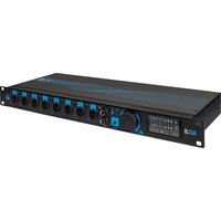
GO.8 - Audio Interface M-Live - Free user manual and instructions
Find the device manual for free GO.8 M-Live in PDF.


User questions about GO.8 M-Live
0 question about this device. Answer the ones you know or ask your own.
Ask a new question about this device
Download the instructions for your Audio Interface in PDF format for free! Find your manual GO.8 - M-Live and take your electronic device back in hand. On this page are published all the documents necessary for the use of your device. GO.8 by M-Live.
USER MANUAL GO.8 M-Live
text_image
GO.8 GO.8MANUALE D'USO
HANDBOOK
MANUAL
HANDBUCH
MANUEL

text_image
LIVEGO.8

flowchart
graph TD
    subgraph Audio Components
        A["B.BEAT A"] -->|Audio out 1/6| B["GO.8 back"]
        C["B.BEAT B"] -->|Audio out 1/6| D["GO.8 front"]
    end
    B -->|Video in A| E["MIDI in A"]
    B -->|Video in B| F["MIDI in B"]
    B -->|MIDI in| G["MIDI device"]
    B -->|MIDI in| H["MIDI device"]
    B --> I["MIDI device"]
    B --> J["MIDI device"]
    B --> K["MIDI device"]
    B --> L["MIDI device"]
    B --> M["MIDI device"]
    B --> N["MIDI device"]
    B --> O["MIDI device"]
    B --> P["MIDI device"]
    B --> Q["MIDI device"]
    B --> R["MIDI device"]
    B --> S["MIDI device"]
    B --> T["MIDI device"]
    B --> U["MIDI device"]
    B --> V["MIDI device"]
    B --> W["MIDI device"]
    B --> X["MIDI device"]
    B --> Y["MIDI device"]
    B --> Z["MIDI device"]
    B --> AA["MIDI device"]
    B --> AB["MIDI device"]
    B --> AC["MIDI device"]
    B --> AD["MIDI device"]
    B --> AE["MIDI device"]
    B --> AF["MIDI device"]
    B --> AG["MIDI device"]
    B --> AH["MIDI device"]
    B --> AI["MIDI device"]
    B --> AJ["MIDI device"]
    B --> AK["MIDI device"]
    B --> AL["MIDI device"]
    B --> AM["MIDI device"]
    B --> AN["MIDI device"]
    B --> AO["MIDI device"]
    B --> AP["MIDI device"]
    B --> AQ["MIDI device"]
    B --> AR["MIDI device"]
    B --> AS["MIDI device"]
    B --> AT["MIDI device"]
    B --> AU["MIDI device"]
    B --> AV["MIDI device"]
    B --> AW["MIDI device"]
    B --> AX["MIDI device"]
    B --> AY["MIDI device"]
    B --> AZ["MIDI device"]
    B --> BA["MIDI device"]
flowchart
graph TD
    subgraph B.BEAT-X_A["BO.8 back"]
        A1["Audio out 1/8"] -->|Midi out| A2["Video Out"]
        A2 -->|Midi in A| A3["Video in A"]
        A3 -->|Midi in B| A4["Video in B"]
        A4 -->|Midi in C| A5["Video in C"]
    end
    subgraph B.BEAT-X_B["BO.8 front"]
        B1["Audio out 1/8"] -->|Midi out| B2["Video Out"]
        B2 -->|Midi in B| B3["Video in B"]
        B3 -->|Midi in C| B4["Video in C"]
    end
    A1 -->|Audio out 1/8| A2
    A2 -->|Audio out 1/8| A3
    A3 -->|Audio in A| A4
    A4 -->|Audio in B| A5
    A5 -->|Audio in C| A6
    A6 -->|Audio in D| A7
    A7 -->|Audio in E| A8
    A8 -->|Audio in F| A9
    A9 -->|Audio in G| A10
    A10 -->|Audio in H| A11
    A11 -->|Audio in I| A12
    A12 -->|Audio in J| A13
    A13 -->|Audio in K| A14
    A14 -->|Audio in L| A15
    A15 -->|Audio in M| A16
    A16 -->|Audio in N| A17
    A17 -->|Audio in O| A18
    A18 -->|Audio in P| A19
    A19 -->|Audio in Q| A20
    A20 -->|Audio in R| A21
    A21 -->|Audio in S| A22
    A22 -->|Audio in T| A23
    A23 -->|Audio in U| A24
    A24 -->|Audio in V| A25
    A25 -->|Audio in W| A26
    A26 -->|Audio in X| A27
    A27 -->|Audio in Y| A28
    A28 -->|Audio in Z| A29
    A29 -->|Audio in AA| A30
    A30 -->|Audio in AB| A31
    A31 -->|Audio in AC| A32
    A32 -->|Audio in AD| A33
    A33 -->|Audio in AE| A34
    A34 -->|Audio in AF| A35
    A35 -->|Audio in AG| A36
    A36 -->|Audio in AH| A37
    A37 -->|Audio in AI| A38
    A38 -->|Audio in AJ| A39
    A39 -->|Audio in AK| A40
    A40 -->|Audio in AL | A41
    A41 -->|Audio in AM | A42
    A42 -->|Audio in AN | A43
    A43 -->|Audio in AO | A44
    A44 -->|Audio in AP | A45
    A45 -->|Audio in AQ | A46
    A46 -->|Audio in AR | A47
    A47 -->|Audio in AS | A48
    A48 -->|Audio in AT | A49
    A49 -->|Audio in AU | A50
    A50 -->|Audio in AV | A51
    A51 -->|Audio in AW | A52
    A52 -->|Audio in AX | A53
    A53 -->|Audio in AZ | A54
    A54 -->|Audio in BA | A55
    A55 -->|Audio in BC | A56
    A56 -->|Audio in DA | A57
    A57 -->|Audio in AE | A58
    A58 -->|Audio in AF | A59
    A59 -->|Audio in AG | A60
    A60 -->|Audio in AH | A61
    A61 -->|Audio in AI | A62
    A62 -->|Audio in AJ | A63
    A63 -->|Audio in AK | A64
    A64 -->|Audio in AL | A65
    A65 -->|Audio in AM | A66
    A66 -->|Audio in AN | A67
    A67 -->|Audio in AO | A68
    A68 -->|Audio in AP | A69
    A69 -->|Audio in AQ | A70
    A70 -->|Audio in AR | A71
    A71 -->|Audio in AS | A72
    A72 -->|Audio in AT | A73
    A73 -->|Audio in AU | A74
    A74 -->|Audio in AV | A75
    A75 -->|Audio in AW | A76
    A76 -->|Audio in AH | A77
    A77 -->|Audio in AI | A78
    A78 -->|Audio in AJ | A79
    A79 -->|Audio in AK | A80
    A80 -->|Audio in AL | A81
    A81 -->|Audio in AR | A82
    A82 -->|Audio in AS | A83
    A83 -->|Audio in AT | A84
    A84 -->|Audio in AU | A85
    A85 -->|Audio in AV | A86
    A86 -->|Audio in AW | A87
    A87 -->|Audio in AH | A88
    A88 -->|Audio in AI | A89
    style GO.8Front fill:#f9f,stroke:#333,stroke-width:2px

text_image
GO ∞BEATX
text_image
B.BEAT PRO16 B B.BEAT PRO16 A C0.8 2 C0.8 1 C0.8 1 Video OUT Audio Out Audio Out Video OUT Video Out Audio In U3 Audio In U4 Audio In U5 Audio In U6 Audio In U7 Audio In U8 Audio In U9 Audio In U10 Audio In U11 Audio In U12 Audio In U13 Audio In U14 Audio In U15 Audio In U16 Audio In U17 Audio In U18 Audio In U19 Audio In U20 Audio In U21 Audio In U22 Audio In U23 Audio In U24 Audio In U25 Audio In U26 Audio In U27 Audio In U28 Audio In U29 Audio In U30 Audio In U31 Audio In U32 Audio In U33 Audio In U34 Audio In U35 Audio In U36 Audio In U37 Audio In U38 Audio In U39 Audio In U40 Audio In U41 Audio In U42 Audio In U43 Audio In U44 Audio In U45 Audio In U46 Audio In U47 Audio In U48 Audio In U49 Audio In U50 Audio In U51 Audio In U52 Audio In U53 Audio In U54 Audio In U55 Audio In U56 Audio In U57 Audio In U58 Audio In U59 Audio In U60 Audio In U61 Audio In U62 Audio In U63 Audio In U64 Audio In U65 Audio In U66 Audio In U67 Audio In U68 Audio In U69 Audio In U70 Audio In U71 Audio In U72 Audio In U73 Audio In U74 Audio In U75 Audio In U76 Audio In U77 Audio In U78 Audio In U79 Audio In U80 Audio In U81 Audio In U82 Audio In U83 Audio In U84 Audio In U85 Audio In U86 Audio In U87 Audio In U88 Audio In U89 Audio In U90 Audio In U91 Audio In U92 Audio In U93 Audio In U94 Audio In U95 Audio In U96 Audio In U97 Audio In U98 Audio In U99 Audio In U100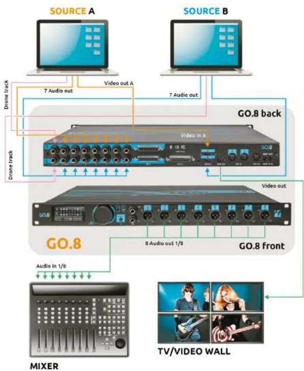
flowchart
graph TD
    A["SOURCE A"] -->|7 Audio out| B["GO.8 back"]
    C["SOURCE B"] -->|7 Audio out| B
    B --> D["GO.8 front"]
    D -->|8 Audio out 1/8| E["MIXER"]
    E --> F["TV/VIDEO WALL"]
    style A fill:#f9f,stroke:#333
    style C fill:#f9f,stroke:#333
    style B fill:#ccf,stroke:#333
    style D fill:#ccf,stroke:#333
    style E fill:#cfc,stroke:#333
    style F fill:#fcc,stroke:#333

INDEX
| 2 | ITALIANO |
| 16 | ENGLISH |
| 26 | DEUTSCH |
| 36 | ESPAÑOL |
| 46 | FRANÇAIS |
GRAZIE PER AVER SCELTO GO.8, LO SWITCH AUTOMATICO
natural_image
Front view of a black GCB audio workstation with multiple ports and control knobs (no visible text or labels)ITAITA
GO.8
MUTE OPTIONS MUTE OPTIONS
text_image
PLAYISTS SHOBS & SCENES time 00:0 Synch Generation Choose the type of signal 21 kHz tone 1 kHz tone Choose the channel on which to direct Synch 1 In the case of a 21 kHz tone, you can add it to another audio signal [two mixed tracks] without having to give up one output channel of the B.Best to dedicate it solely to the Synch function. GENERATE CANCEL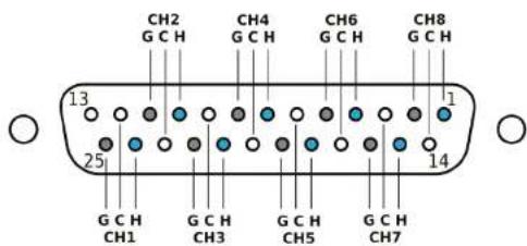
text_image
CH2 G C H CH4 G C H CH6 G C H CH8 G C H 13 1 25 14 G C H CH1 G C H CH3 G C H CH5 G C H CH7H=Hot/Positive, C=Cold/Negative, G=Ground
| Input AudioA and B groups | - 2x8 Line Input on Jack 6.35 mm TRS, balanced (or unbalanced with TS cable)- 2x8 Line Input on DB25, balanced- Impedance >15 kΩ- Maximum amplitude +20 dBu, unbalanced |
| Output Audio Front(XLR) | - 8 Audio Output XLR with 3 poles, balanced- Impedance 600 Ω- Gain: -20 dB- Features: Mute, GND LIFT |
| Output Audio Rear(DB25) | - 8 Audio output on DB25, balanced- Gain: 0 dB- Not transformer isolated |
| Frequency response | 10 Hz up to 20 kHz |
| Link with other units | 1x Link In Jack 6.35 mm TRS1x Link Out Jack 6.35 mm TRSTo be linked with TRS Cable only. |
| Display | 2.4" OLED, 128x64 |
| MIDI | 2xMIDI IN (groups A and B)1xMIDI OUT |
| Video | 2xIN (groups A and B)1xOutputResolution:- 1920x1080 - 60 Hz- 3840x2160 - 30 Hz (4k)Cables HDMI V 1.4 |
| Synch signal | 1 kHz sine wave audio signal detected on channel 8 (groups A and B)Minimum signal level:- balanced -12 dBu- unbalanced -6 dBu |
| Timecode SMPTE | SMPTE timecode decoding (LTC signal) performed on channel 7 (for both input groups A and B)Minimum signal level:- balanced -12 dBu- unbalanced -6 dBu |
| Power supply input | 12 VDC, 2 A, consumption max < 4 WDouble input for redundancy |
| Power supply | AC/DC Adaptor Mod. 13/90288-00 INPUT 100-240VAC Freq 50-80Hz OUTPUT12VDC - 2A |
| Weight and Dimension | 48 x 18 x 4,5 cm - 2.5 Kg. |
text_image
EN GO.8
text_image
EN GO.8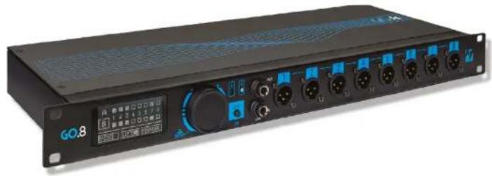
natural_image
Front view of a black GO.8 audio workstation with multiple ports and control knobs (no visible text or symbols on main body)THANK YOU FOR CHOOSING GO.8, THE AUTOMATIC SWITCH
60.8 is an automatic switch for redundant backup management. If you use sequences to accompany your musical performances, and not only that, you know how important device reliability is. Unfortunately, it can happen that a sequence stops due to a sudden crash. To minimise the impact of a Crash on the stage, a redundant system must be used, where there will be two machines playing the Sequences: the Main machine and the Spare machine. These two machines are activated and play in synchronism, either by hand or by special signals and techniques. If the Main machine crashes, the spare machine steps in, so the show goes on. Switching between Main and Spare machines can be done manually on
the mixer, but using GO.8 it will be done automatically seamlessly and without engaging twice as many channels on the stage mixer.
60.8 can automatically switch 8 audio channels, one Midi line, and one video line. Switching can take place between two audio players such as computers with sequencers, or two B.Beat or other sound and/or video sources. Basically, by having a redundant system (i.e. consisting of a Main and Spare machine) GO.8 automatically (or even manually) handles the automatic switch in the event of a crash.
GO.8 works perfectly with all Player sy-
stems: any Audio Backing Tracks player such as Computer or others. It expresses its full potential when used with M-Live products, especially those from the B.Beat range.
If you use GO.8 with B.Beat, you will have some advantages that we summarise:
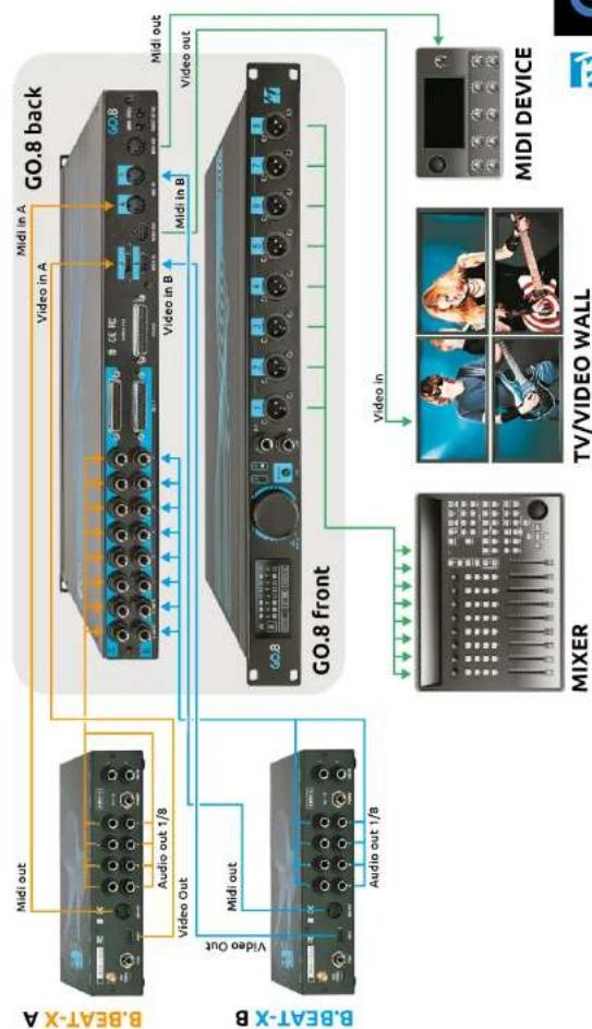
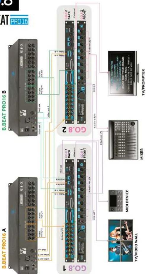
1.1 It will not be necessary to engage an output channel for the synch DRO-NE track.
2.2 Midi tracks played by B.Beat can be handled redundantly.
3.3 A video track managed by B.beat can be managed in a redundant manner.
GO.8 utilises a gate that detects the crash of the main machine and switches to the 'backup' machine in real time, ensuring continuity even in the event of a sequencer failure.
Two groups of audio inputs (with 8 balanced channels), two video inputs and two Midi inputs are available, and switching between the two groups is done automatically via a specific SYNCH audio signal (sinusoidal, 1 kHz frequency) on channel 8 of the GO.8. As soon as a lack of this signal is detected, the device switches to input group B (redundant). Switching can also be managed manually via the
SELECT button on the front panel.
For complex configurations, multiple G0.8s can be linked together, creating 16-, 24- or 32-track systems. Housed in a sturdy 19° G0.8 steel rack, it has a choice of 25-pin D-sub or 1/4" TRS input connectors with D-Sub and XLR outputs. The XLR sockets on the front panel produce a DI signal with balanced microphone level to feed a snake system and are transformer-isolated to eliminate hum and noise caused by ground loops. D-Sub connectors at the rear of the panel provide direct line-level balanced connectivity.
GO.8 has a function for reading SMPTE timecode as an LTC signal from channel 7 (both group A and B) for real-time verification of the timecode value.
ON STAGE WITHOUT WORRIES, GO.8
Just Play!
text_image
EN GO.8FRONT PANEL

text_image
60.8 1 2 3 4 5 6 7 8GO.8 fits into the Rack cabinet where it can be accommodated for an excellent logistical solution. The front panel features an OLED display that is perfect for visibility in low light conditions, an Alpha Dial with Enter button included (pressing the Alpha Dial activates Enter), a button for manual switching from desk A to B, connections for Linked mode that allows two or more GO.8s to be joined when you have more than 8 audio channels to be redundant, 8 audio outputs to go to the hall mixer.
BACK PANEL

The back panel includes:
• 8 Audio Jack In connectors for Audio Desk A
• 8 Audio Jack In connectors for Audio Desk B
• 2 DB25 connectors for input of audio desks A and B
- A DB25 connector for the output of the 8 channels to the hall mixer.
- Two VIDEO IN connectors for desk A and B, signal input.
• VIDEO OUT connector for signal output to video
- Two Midi IN connectors for desk A and B, signal input
• MIDI OUT connector for signal output to MIDI devices.
- Two power supply inputs, which can be redundant.
DISPLAY AND SCREENS DISPLAY AND SCREENS-T: LIFT: The ground lift option physi-
The GO.8 software has three screens: the main screen, the SMPTE management screen, and the SYSTEM screen for main settings.
To switch between screens, rotate the Alpha Dial. To enter the SYSTEM screen, go to the same screen with Alpha Dial and press ENTER.
MAIN SCREEN MAIN SCREEN
text_image
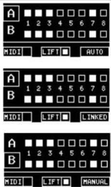
A B MIDI LIFT AUTO A B MIDI LIFT LINKED A B MIDI LIFT MANUALOn the 60.8 main screen, you can see in white what audio channels are used and connected. In the line below:
MIDI:MIDI: indicates the status of the Midi channel, whether active or not. It flashes when receiving Midi signals.
cally disconnects the ground output cables. This in some cases is sufficient to eliminate background noise due to the ground-loop connection of the various interconnected devices. Normally it should be left disabled and only enabled in the event of ground noise.
AUTO, MANUAL, LINKED AUTO, MANUAL, whether the devices are controlled in Automatic mode or if the switch is made via the button, in manual mode. In the case of two GO.8s connected together to expand channels, a balanced TRS audio cable connected from the LINK OUT port of the first to the LINK IN port of the second must be used. An unbalanced TS cable is not good for this synchronisation signal. On the first GO.8 it will say AUTO or MANUAL depending on the chosen setting, while the second GO.8 will say LINKED to indicate that it is controlling the first GO.8.
SMPTE SCREEN SMPTE SCREEN
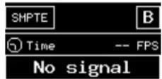
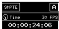
When connected to an SMPTE signal, the GO.8 acts as an SMPTE signal display. To connect GO.8 to an SMPTE signal, the cable transmitting the signal must be connected to channel XXX. From that moment on, the GO.8 is able to show the SMPTE signal.
It is not possible to choose from where to read the SMPTE signal, it is taken from channel 7 of the group (A or B) active at
text_image
EN GO.8that time. The two screens show the two cases: presence or absence of signal
To reach the System screen rotate the alpha dial until it appears and press ENTER (press Alpha Dial) to enter the screen:
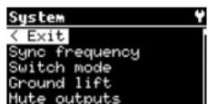
From this page you can select the various entries, rotate the Alpha Dial and press enter to select the function we need to edit. Press ENTER on Exit to leave the System page.
SYNC FREQUENCY SYNC FREQUENCY
Choose the frequency of the Synch signal and press Enter. Select Back and press Enter to exit.
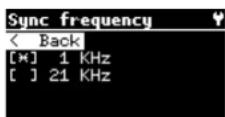
SWITCH MODESWITCH MODE
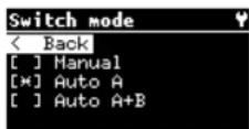
Choose the Switch Mode function to define in which mode the switch between the two machines connected to GO.8 will take place.
MANUAL MANUAL
If you want to use the manual switch, select Manual. In this case, the switch will be made by pressing the selector button on the front panel of the G0.8, which selects group A or group B.
AUTO A: AUTO A:
GO.8 switches to B when there is no Synch signal on A. In this mode when B.Beat is at stop, GO.8 is on B and switches to A when B.Beat is at play.
If AUTO is chosen, the switch will be made automatically by the Drone track.
text_image
EN GO.8AUTO A+BAUTO A+B
To be used when using VIDEO with TV / MONITOR connections.
To be used when using MIDI channels with Midi In and OUT connections.
When using two GO.8s in LINKED mode, the second GO.8 takes over the settings made on the first GO.8 in the chain.
GO.8 switches to B when the A signal is not present but the B signal is present. In this mode when B.Beat is at stop, GO.8 is on A and stays on A even when B.Beat is at play. GO.8 only switches when B.Beat A. crashes.
This serves to decrease the number of times GO.8 has to switch, which has 2 advantages:
1.1. the TV does not momentarily lose signal (black screen)
2.2. extends the life of the relays.
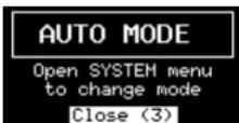
When the AUTO Switch mode is selected and the SELECT AB button is pressed, this message will appear for 3 seconds.
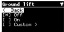
Choose the Ground Lift function to change the ground output settings. There are
three possibilities: off, on and custom. The option ground lift ON physically disconnects the cables of the ground outputs. This in some cases is sufficient to eliminate any background noise due to the ground-loop connection of the various interconnected devices.
Normally it should be left disabled and only enabled in the event of ground noise.
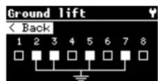
Ground LIFT Custom: allows you to choose which channels to connect to GROUND. Press ENTER to activate ground connection.
Press enter again to deactivate the connection. Turn the Alpha Dial to select the intervention channel.
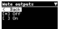
MUTE OPTIONS MUTE OPTIONS
The MUTE function allows you to MUTE all GO.8 outputs. If activated, a message appears warning of this status. In fact, a GO.8 in MUTE position does not play.
Here is the message:
text_image
EN GO.8
text_image
EN GO.8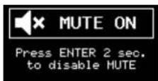
To cancel MUTE press and hold ENTER (alpha dial) for 2 seconds.
nerally use as a reference). It is important that the track has no initial silence and that the duration is equal to that of the longest audio track in the project being edited.
The generated audio track should be routed to input channel 8 of GO.8
USING 30.8 WITH B.BEATUSING GO.8 WITH B.BEAT
There are two options:
1.1. use a dedicated Synch track with a 1 kHz signal, this option will engage
RACKudio channel and one track.
- Use a track where you can record a 21 kHz signal, this option allows you not to engage one channel for the Synch signal.
SYNCI OR DRONE TRACKSYNCH OR
The Synch or Drone track allows the two machines to be synchronised and managed in redundancy by the GO.8. This particular signal must always be sent to GO.8's audio channel 8 in order to function properly.
If more than one GO.8 is used in cascade, the DRONE track should be routed to the first GO.8 in the series.
SYNCH TRACK FOR GO.8 WITH COMPUTER PUTER
Connection diagram between Computer and GO.8
To generate a synchronisation track for GOB you can use your Daw: in the project, add an audio track and generate a signal with a sine tone at a frequency of 1 kHz and amplitude of 0 dB (or the value you ge-
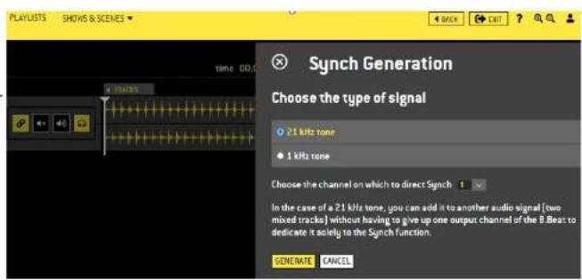
The Synch track is written with B.Beat manager version 4.7 or later. To do this, enter the editing of the Audio project. At the top right is the G0.8 button that opens the Sync signal configuration window.
The Synch signal can be a 1 kHz tone (mode 1) or a 21 kHz tone (mode 2), and also the audio OUT channel to which the synch track should be routed. In the case of a 21 kHz tone, you can add it to another audio signal (two mixed tracks) without having to give up one output channel of the
B. Beat to dedicate it solely to this Synch function. The configuration in this case is prepared automatically by the system.
text_image
PLAYLISTS SHOWS & SCENES time 00:00 Synch Generation Choose the type of signal 21 kHz tone 1 kHz tone Choose the channel on which to direct Synch 1 In the case of a 21 kHz tone, you can add it to another audio signal [two mixed tracks] without having to give up one output channel of the B.Best to dedicate it solely to the Synch function. SENE RATE CANCEL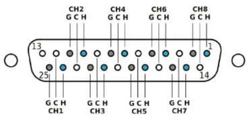
text_image
CH2 G C H CH4 G C H CH6 G C H CH8 G C H 13 1 25 14 G C H CH1 G C H CH3 G C H CH5 G C H CH7H=Hot/Positive, C=Cold/Negative, G=Ground
| Input AudioA and B groups | - 2x8 Line Input on Jack 6.35 mm TRS, balanced (or unbalanced with TS cable)- 2x8 Line Input on DB25, balanced-Impedance >15 kΩ-Maximum amplitude +20 dBu, unbalanced |
| Output Audio Front(XLR)H GO 8 IN | - 8 Audio Output XLR with 3 poles, balanced-Impedance 600 Ω-Gain: -20 dB- Features: Mute, GND LIFT |
| Output Audio Rear(DB25) | - 8 Audio output on DB25, balanced-Gain: 0 dB- Not transformer isolated |
| Frequency response | 10 Hz up to 20 kHz |
| Link with other units | 1x Link In Jack 6.35 mm TRS1x Link Out Jack 6.35 mm TRSTo be linked with TRS Cable only. |
| Display | 2.4" OLED, 128x64 |
| MIDI | 2xMIDI IN (groups A and B)1xMIDI OUT |
| Video | 2xIN (groups A and B)1xOutputResolution:- 1920x1080 - 60 Hz- 3840x2160 - 30 Hz (4k)Cable HDMV 1.4 |
| Synch signal | 1 kHz sine wave audio signal detected on channel 8 (groups A and B)Minimum signal level:- balanced -12 dBu-unbalanced -6 dBu |
| Timecode SMPTE | SMPTE timecode decoding (LTC signal) performed on channel 7 (for both input groups A and B)Minimum signal level:- balanced -12 dBu-unbalanced -6 dBu |
| Power supply input | 12 VDC, 2 A, consumption max < 4 WDouble input for redundancy |
| Power supply | AC/DC Adaptor Mod. 13/90288-00 INPUT 100-240VAC Freq 50-60Hz OUTPUT12VDC - 2A |
| Weight and Dimension | 48 x 18 x 4,5 cm - 2.5 Kg. |
text_image
DE GO.8
text_image
DE GO.8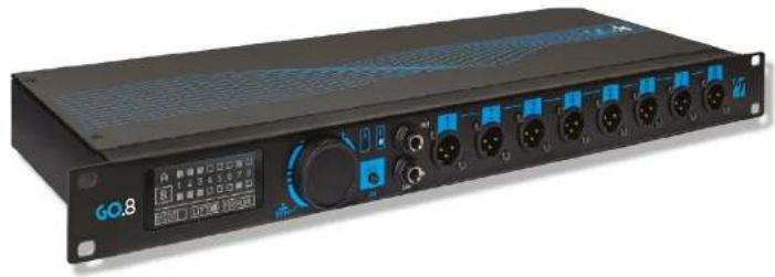
natural_image
Front view of a black GO.8 audio workstation with multiple ports and a digital display (no readable text or symbols on the device body)DAS HINTERE BEDIENFELD

text_image
A + B CE 障 快 www.123.com + - B + - A B www.123.com + - B + - A B www.123.comMUTE OPTIONS MUTE OPTIONS
text_image
PLAYISTS SHOWS & SCENES Synch Generation Choose the type of signal 21 kHz tone 1 kHz tone Choose the channel on which to direct Synch 1 In the case of a 21 kHz tone, you can add it to another audio signal (two mixed tracks) without having to give up one output channel of the 8. Best to dedicate it solely to the Synch function. GENE RATE CANCEL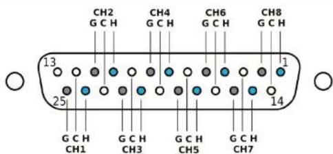
text_image
CH2 G C H CH4 G C H CH6 G C H CH8 G C H 13 1 25 14 G C H CH1 G C H CH3 G C H CH5 G C H CH7H=Hot/Positive, C=Cold/Negative, G=Ground
| Input AudioA and B groups | - 2x8 Line Input on Jack 6.35 mm TRS, balanced (or unbalanced with TS cable)- 2x8 Line Input on DB25, balanced- Impedance >15 kΩ- Maximum amplitude +20 dBu, unbalanced |
| Output Audio Front(XLR)GO 8 IM | - 8 Audio Output XLR with 3 poles, balanced- Impedance 600 Ω- Gain: -20 dB- Features: Mute, OND LIFT |
| Output Audio Rear(DB25) | - 8 Audio output on DB25, balanced- Gain: 0 dB- Not transformer isolated |
| Frequency response | 10 Hz up to 20 kHz |
| Link with other units | 1x Link In Jack 6.35 mm TRS1x Link Out Jack 6.35 mm TRSTo be linked with TRS Cable only. |
| Display | 2.4" OLED, 128x64 |
| MIDI | 2xMIDI IN (groups A and B)1xMIDI OUT |
| Video | 2xIN (groups A and B)1xOutputResolution:- 1920x1080 - 60 Hz- 3840x2160 - 30 Hz (4k)Cables HDMI V 1.4 |
| Synch signal | 1 kHz sine wave audio signal detected on channel 8 (groups A and B)Minimum signal level:- balanced -12 dBu- unbalanced -6 dBu |
| Timecode SMPTE | SMPTE timecode decoding (LTC signal) performed on channel 7 (for both input groups A and B)Minimum signal level:- balanced -12 dBu- unbalanced -6 dBu |
| Power supply input | 12 VDC, 2 A, consumption max < 4 WDouble input for redundancy |
| Power supply | AC/DC Adaptor Mod. 13/90288-00 INPUT 100-240VAC Freq 50-60Hz OUTPUT12VDC - 2A |
| Weight and Dimension | 48 x 18 x 4,5 cm - 2.5 Kg. |
ES
GO.8
ES
GO.8
natural_image
Front view of a black GO.B audio workstation with multiple knobs and a display (no readable text or symbols)MUTE CPTIONS MUTE OPTIONS
text_image
PLAYISTS SHOBS & SCENES time 00:00 Synch Generation Choose the type of signal 21 kHz tone 1 kHz tone Choose the channel on which to direct Synch 1 In the case of a 21 kHz tone, you can add it to another audio signal [two mixed tracks] without having to give up one output channel of the B.Best to dedicate it solely to the Synch function. GENERATE CANCEL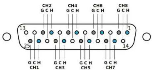
text_image
CH2 G C H CH4 G C H CH6 G C H CH8 G C H 13 1 25 14 G C H CH1 G C H CH3 G C H CH5 G C H CH7H=Hot/Positive, C=Cold/Negative, G=Ground
| Input AudioA and B groups | - 2x8 Line Input on Jack 6.35 mm TRS, balanced (or unbalanced with TS cable)- 2x8 Line Input on DB25, balanced-Impedance >15 kΩ-Maximum amplitude +20 dBu, unbalanced |
| Output Audio Front(XLR) | - 8 Audio Output XLR with 3 poles, balanced-Impedance 600 Ω-Gain: -20 dB- Features: Mute, GND LIFT |
| Output Audio Rear(DB25) | - 8 Audio output on DB25, balanced-Gain: 0 dB- Not transformer isolated |
| Frequency response | 10 Hz up to 20 kHz |
| Link with other units | 1x Link In Jack 6.35 mm TRS1x Link Out Jack 6.35 mm TRSTo be linked with TRS Cable only. |
| Display | 2.4" OLED, 128x64 |
| MIDI | 2xMIDI IN (groups A and B)1xMIDI OUT |
| Video | 2xIN (groups A and B)1xOutputResolution:- 1920x1080 - 60 Hz- 3840x2160 - 30 Hz (4k)Cable HDMV 1.4 |
| Synch signal | 1 kHz sine wave audio signal detected on channel 8 (groups A and B)Minimum signal level:- balanced -12 dBu-unbalanced -6 dBu |
| Timecode SMPTE | SMPTE timecode decoding (LTC signal) performed on channel 7 (for both input groups A and B)Minimum signal level:- balanced -12 dBu-unbalanced -6 dBu |
| Power supply input | 12 VDC, 2 A, consumption max < 4 WDouble input for redundancy |
| Power supply | AC/DC Adaptor Mod. 13/90288-00 INPUT 100-240VAC Freq 50-60Hz OUTPUT12VDC - 2A |
| Weight and Dimension | 48 x 18 x 4,5 cm - 2.5 Kg. |
text_image
FR GO.8
text_image
FR GO.8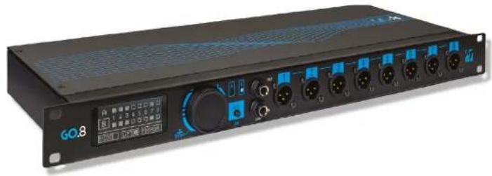
natural_image
Front view of a black GO.8 audio workstation with multiple ports and a digital display (no readable text or symbols on the device body)MERCI D'AVOIR CHOISI GO.8, LE SWITCH AUTOMATIQUE
MUTE OPTIONS MUTE OPTIONS
UTLISER GO.8 AVEC B.3CATUTILISER GO.8 AVEC B
text_image
PLAYISTS SHOBS & SCENES Synch Generation Choose the type of signal 21 kHz tone 1 kHz tone Choose the channel on which to direct Synch 1 In the case of a 21 kHz tone, you can add it to another audio signal (two mixed tracks) without having to give up one output channel of the B.Beat to dedicate it solely to the Synch function. GENERATE CANCEL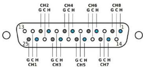
text_image
CH2 G C H CH4 G C H CH6 G C H CH8 G C H 13 1 25 14 G C H CH1 G C H CH3 G C H CH5 G C H CH7H=Hot/Positive, C=Cold/Negative, G=Ground
| Input AudioA and B groups | - 2x8 Line Input on Jack 6.35 mm TRS, balanced (or unbalanced with TS cable)- 2x8 Line Input on DB25, balanced- Impedance >15 kΩ- Maximum amplitude +20 dBu, unbalanced |
| Output Audio Front(XLR) | - 8 Audio Output XLR with 3 poles, balanced- Impedance 600 Ω- Gain: -20 dB- Features: Mute, GND LIFT |
| Output Audio Rear(DB25) | - 8 Audio output on DB25, balanced- Gain: 0 dB- Not transformer isolated |
| Frequency response | 10 Hz up to 20 kHz |
| Link with other units | 1x Link In Jack 6.35 mm TRS1x Link Out Jack 6.35 mm TRSTo be linked with TRS Cable only. |
| Display | 2.4" OLED, 128x64 |
| MIDI | 2xMIDI IN (groups A and B)1xMIDI OUT |
| Video | 2xIN (groups A and B)1xOutputResolution:- 1920x1080 - 60 Hz- 3840x2160 - 30 Hz (4k)Cable HDMV 1.4 |
| Synch signal | 1 kHz sine wave audio signal detected on channel 8 (groups A and B)Minimum signal level:- balanced -12 dBu- unbalanced -6 dBu |
| Timecode SMPTE | SMPTE timecode decoding (LTC signal) performed on channel 7 (for both input groups A and B)Minimum signal level:- balanced -12 dBu- unbalanced -6 dBu |
| Power supply input | 12 VDC, 2 A, consumption max < 4 WDouble input for redundancy |
| Power supply | AC/DC Adaptor Mod. 13/90288-00 INPUT 100-240VAC Freq 50-60Hz OUTPUT12VDC - 2A |
| Weight and Dimension | 48 x 18 x 4,5 cm - 2.5 Kg. |
Dicembre 2024
GO.8

text_image
LIVEM-Live Srl
Via Luciona 1872/B, 47842 San Giovanni in Marignano (RN)
Tel: (+39) 0541 827066 Fax: (+39) 0541 827067
m-live.com