
PowerEdge R6715 - Server DELL - Free user manual and instructions
Find the device manual for free PowerEdge R6715 DELL in PDF.

| Product type | 1U rack server |
| Dimensions (W x D x H) | 482 x 786.14 x 42.8 mm (with front panel) |
| Maximum weight | 21.19 kg (10 SAS/SATA drives configuration) |
| Processor | AMD EPYC 9005 series (5th generation) up to 160 cores, 1 processor |
| Memory | 24 DDR5 RDIMM slots, up to 6 TB (256 GB per DIMM) |
| Front storage | Up to 20 EDSFF E3.S Gen5 NVMe drives + 2 rear NVMe drives |
| Power | Redundant AC/DC hot-swappable power supply units |
| Remote management | iDRAC with dedicated 1 Gbps BMC Ethernet port, IPMI 2.0 |
| Operating systems | Windows Server, Ubuntu Server LTS, RHEL, SUSE Linux Enterprise Server, VMware ESXi |
| Front connectors | 1 USB 2.0 Type-A (KVM), 1 Mini DisplayPort, 1 USB 2.0 Type-C (HOST/BMC) |
| Rear connectors | 2 USB 3.1 Type-A, 1 VGA, 1 GbE BMC, 2 OCP 3.0, BOSS-N1 |
| Cooling | 4 dual-module fan sets, hot-swappable |
| Operating temperature | 10 to 35 °C (A2) or 5 to 45 °C (A4) depending on configuration |
| Serviceability | Hot-swappable disks, power supply units and fans |
| Security | Intrusion switch, system password, TPM 2.0 module |
| Warranty | 3 years standard (extendable) |
Frequently Asked Questions - PowerEdge R6715 DELL
User questions about PowerEdge R6715 DELL
0 question about this device. Answer the ones you know or ask your own.
Ask a new question about this device
Download the instructions for your Server in PDF format for free! Find your manual PowerEdge R6715 - DELL and take your electronic device back in hand. On this page are published all the documents necessary for the use of your device. PowerEdge R6715 by DELL.
USER MANUAL PowerEdge R6715 DELL
Dell PowerEdge R6715
PSU specifications....34
Removing a cooling fan....57
Installing a cooling fan....58
Support central....76
Removing the Direct Liquid Cooling(DLC)....99
Installing the Direct Liquid Cooling(DLC)....101
Removing the heat sink....102
Removing the processor....103
Installing the processor....105
Installing the heat sink....107
Expansion card installation guidelines....109
Removing the expansion card risers....112
Installing the expansion card risers....114
Removing an expansion card from the expansion card riser....116
Installing an expansion card into the expansion card riser....118
Module SSD M.2....120
Removing the rear OCP NIC card....127
Installing the rear OCP NIC card....129
Removing the DC-SCM board....130
Installing the DC-SCM board....131
Carte Attic....132
Removing the Attic board....132
Installing the Attic board....133
Removing the internal USB card....136
Installing the Internal USB card....136
Replacing the system battery....137
Module TPM (Trusted Platform Module)....144
Removing the HPM board....145
Installing the HPM board....146
Removing the Left Control Panel (LCP) - Secondary....149
Installing the Left Control Panel (LCP) - Secondary....151
Contacter Dell Technologies....167
natural_image
Simple diagram of a rectangular object with a vertical seam and a labeled arrow pointing to it (no text or symbols present)natural_image
Close-up of a rectangular device with a vertical panel and a small sensor icon, labeled '1' (no text or symbols on the device itself)The PowerEdge R6715 système supports up to two AC or DC power supply units (PSUs).
Table 18. PSU specifications
| PSU Class Heat dissipation (maximum) | (BTU/hr) | Frequency (Hz) | Input voltage Current (A) | |
| 1800 W Titanium * Titanium | 6750 50/60 20 | 0-240 Vac 9.8-8.2 | ||
| N/A 6750 N/A 24 | Vdc 8.2 | |||
| 1500 W Titanium Titanium | 5625 50/60 100 | 240 Vac 12-8.2 | ||
| N/A 5625 | N/A 240 Vdc 6.8 | |||
| 1500 W 277 Vac & HVDC × | Titanium 5625 50 | 60 277 Vac 6.1 | ||
| N/A 5625 | N/A 366 Vdc 4.91 | |||
| 1400 W -48 Vdc | Telco | 5310 | N/A | (-48) - (-60)Vdc |
| 1100 W Titanium | Titanium | 4125 | 50/60 | 100-240 Vac |
| N/A 4125 | N/A 240 Vdc 5.1 | |||
| 1100 W Platinum | Platinum | 4125 | 50/60 | 100-240 Vac |
| N/A 4125 | N/A 240 Vdc 5.1 | |||
| 800 W Titanium | Titanium 3000 50 | 60 100-240 Vac 9.2-4.5 | ||
| N/A 3000 | N/A 240 Vdc 3.7 | |||
| 800 W Platinum | Platinum | 3000 | 50/60 | 100-240 Vac |
| N/A 3000 | N/A 240 Vdc 3.7 | |||
NOTE: If a system with AC 1500 W PSUs operates at low line 100-120 Vac, then the power rating per PSU is d e-rated to 1050 W.
NOTE: * Feature not available at product launch in June, 2025. Please refer to the product configurator page on Dell.com to confirm feature availability.
NOTE: Heat dissipation is calculated using the PSU wattage rating.
NOTE: Lorsque vous sélectionnez ou mettez à niveau la configuration du système, vérifiez sa consommation électrique avec l'outil Enterprise Infrastructure Planning Tool, disponible à l'adresse calc, pour assurer une utilisation optimale de l'alimentation.
NOTE: If a system with AC 1500 W PSUs operates at low line 100-120 Vac, then the power rating per PSU is d e-rated to 1050 W.
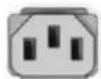
C13
Figure 29. C13 power cord
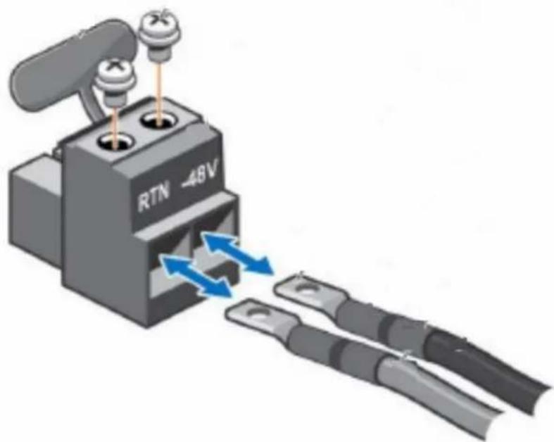
natural_image
Illustration of a RTN 48V power connector with two terminal blocks and a valve, showing bidirectional arrows indicating flow or connection (no text or symbols beyond component labels)Figure 30. DC PSU power cord
Table 19. PSU power cables
| Form factor Output Power cable | ||
| Redundant 60 mm 1800 W Titanium mixed mode * C13 | ||
| Redundant 60 mm 1500 W Titanium mixed mode C13 | ||
| Redundant 60 mm 1500 W 277 Vac and HVDC * APP/Saf-D-Grid | ||
| Redundant 60 mm 1400 W Telco DC power cable | ||
| Redundant 60 mm 1100 W Titanium mixed mode C13 | ||
| Redundant 60 mm 1100 W Platinum mixed mode C13 | ||
| Redundant 60 mm 800 W Titanium mixed mode C13 | ||
| Redundant 60 mm 800 W Platinum mixed mode C13 |

NOTE: ✗ Feature not available at product launch in June, 2025. Please refer to the product configurator page on Dell.com to confirm feature availability.
- Follow the safety guidelines listed in the Safety instructions.
- Follow the procedure listed in Before working inside your system.
Steps
Holding the orange and black edges on the fan module, lift the cooling fan module to disconnect from the connector on the fan board.

natural_image
3D rendering of an electronic device with two fans and a highlighted component, showing internal circuitry (no text or symbols)Figure 37. Removing a cooling fan
Next steps
Replace a cooling fan.
- Follow the safety guidelines listed in the Safety instructions.
- Follow the procedure listed in Before working inside your system.
Steps
Align and lower the cooling fan onto the connector on the fan board. Press the orange touch point on the cooling fan module until it is firmly connected.
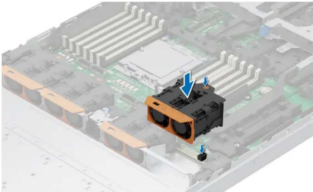
natural_image
3D rendering of an electronic device with a highlighted CPU socket and blue arrows indicating components (no text or symbols present)Figure 38. Installing a cooling fan
Next steps
Follow the procedure listed in After working inside your system.
natural_image
Black plastic electronic device casing with a blue arrow indicating direction (no text or symbols visible)natural_image
Close-up of a black plastic electronic component with two arrows pointing to its sides, no visible text or symbols.natural_image
Black plastic electronic device casing with a blue arrow pointing to a component (no text or symbols visible)natural_image
3D diagram of a mechanical device with blue arrows indicating directional flow or movement, no text or symbols present.natural_image
Diagram of a device with labeled components and directional arrows indicating motion (no text or symbols present)natural_image
3D diagram of a computer drive chassis with cable connectors and a blue arrow indicating motion (no text or symbols)natural_image
3D illustration of a black electronic device with a scroll wheel and blue directional arrows indicating motion (no text or symbols)Figure 47. Installation d'un support de disque NVMe EDSFF E3.S Gen 5
natural_image
3D diagram of a device with a black rectangular block and attached metal frame, showing cable routing (no text or symbols)natural_image
Black circular icon with a white star-like shape at center (no text or symbols)natural_image
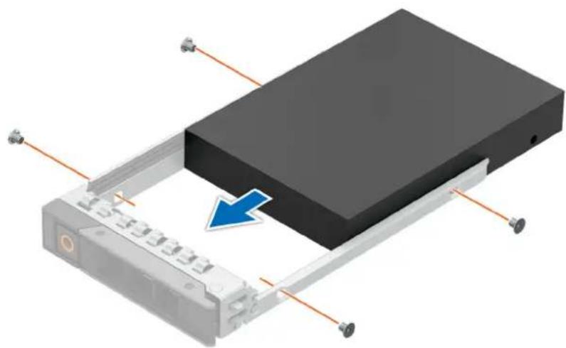
Illustration of a hard disk drive with attached circuit board and screw base (no text or symbols)natural_image
3D rendering of a device chassis with a blue arrow pointing to the top panel (no text or symbols visible)natural_image
Black circular icon with a white six-pointed star at center (no text or symbols)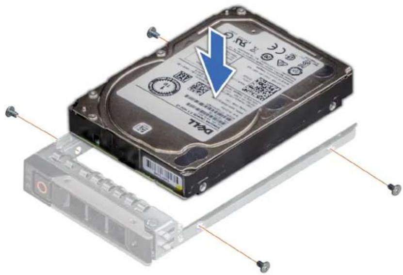
natural_image
Disassembled hard disk with a blue arrow pointing to its internal structure, showing internal components and mounting hardware (no text or symbols on the disk itself)natural_image
3D rendering of a device with a blue arrow pointing to a black rectangular component, mounted on a silver frame (no text or symbols visible)Figure 55. Fond de panier SAS/SATA de 3,5 pouces\*
natural_image
3D diagram of an electronic device chassis with a central drive and blue directional arrows indicating movement or force (no text or symbols present)natural_image
3D rendering of an electronic device chassis with a blue arrow pointing to a component, showing internal circuitry and no visible text or symbols.natural_image
3D rendering of a computer chassis with visible internal components and mounting hardware (no text or symbols)natural_image
3D rendering of a mechanical assembly with green internal components and blue directional arrows indicating flow or movement (no text or symbols)natural_image
3D rendering of a mechanical assembly with a black plastic component and blue directional arrows indicating motion (no text or symbols)natural_image
3D rendering of a mechanical assembly with a black plastic component and blue directional arrows indicating movement or force (no text or symbols)Figure 64. Retrait du support central
Étapes suivantes
Figure 65. Installation du support central
Étapes suivantes
natural_image
3D diagram of an electronic device showing internal components and a highlighted circuit board (no text or symbols)natural_image
3D diagram of a mechanical assembly with labeled components (no readable text or symbols)natural_image
3D diagram of an electronic device showing internal components and a highlighted connection point (no text or symbols present)natural_image
3D rendering of an electronic device chassis with labeled components (no text or symbols visible)natural_image
3D illustration of a computer motherboard with an electronic component and blue directional arrows indicating movement or change (no text or symbols present)natural_image
3D illustration of a computer motherboard with a disassembled electronic component and blue arrows indicating parts of the disc (no text or symbols present)- Follow the safety guidelines listed in the Safety instructions.
- Follow the procedure listed in Before working inside your system.

WARNING: The memory modules are hot to touch for some time after the system has been powered off. Allow the memory modules to cool before handling them.

NOTE: For proper system cooling, memory module blanks must be installed in any memory socket that is not populated. Remove the memory module blanks only if you intend to install the memory module in these sockets. DIMM blanks are only required when the CPU TDP is equal or greater than 225 W. CPU with TDP less that 225 W do not require DIMM blanks.
Steps
- Locate the appropriate memory module socket.
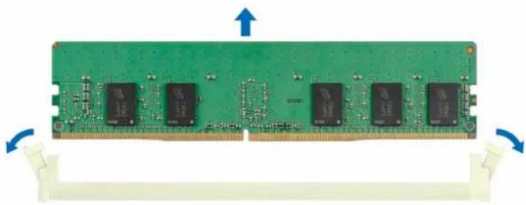
- To release the memory module from the socket, simultaneously press the ejectors on both ends of the memory module socket to fully open.

CAUTION: Handle each memory module only by the card edges, ensuring not to touch the middle of the memory module or metallic contacts.
- Lift the memory module away from the system.
natural_image
Green RAM module with multiple black integrated circuits and blue directional arrows indicating orientation (no text or symbols on the circuit itself)Figure 89. Removing a memory module
Next steps
Replace the memory module.
Installing a memory module
Prerequisites
- Follow the safety guidelines listed in the Safety instructions.
- Follow the procedure listed in Before working inside your system.
Steps
- Locate the appropriate memory module socket.

CAUTION: Handle each memory module only by the card edges, ensuring not to touch the middle of the memory module or metallic contacts.

NOTE: Ensure that the socket ejector latches are fully open before installing the memory module.
- Align the edge connector of the memory module with the alignment key of the memory module socket, and insert the memory module in the socket.

CAUTION: To prevent damage to the memory module or the memory module socket during installation, do not bend or flex the memory module. Insert both ends of the memory module simultaneously.

NOTE: The memory module socket has an alignment key that enables you to install the memory module in the socket in only one orientation.

CAUTION: Do not apply pressure at the center of the memory module; apply pressure at both ends of the memory module evenly.
- Press the memory module with your thumbs until the ejectors firmly click into place. When the memory module is properly seated in the socket, the memory module socket levers align with the levers on the other sockets that have memory modules that are installed.

natural_image
Close-up of a green RAM module with multiple integrated circuits and a magnified inset showing a close-up edge detail (no text or symbols visible)Figure 90. Installing a memory module
Next steps
- Follow the procedure listed in After working inside your system.
- To verify that the memory module has been installed properly, press F2 during reboot and click System Setup Main Menu > System BIOS > Memory Settings. In the Memory Settings screen, the System Memory Size must reflect the updated capacity of the installed memory.
- If the System Memory Size is incorrect, one or more of the memory modules may not be installed properly. Shut down the system and ensure that the memory modules are firmly seated in the correct sockets.
- Run the system memory test in system diagnostics.
Removing the Direct Liquid Cooling(DLC)
Prerequisites
- Follow the safety guidelines listed in the Safety instructions.
- Follow the procedure listed in the Before working inside your system.
- WARNING: The Direct liquid cooling (DLC) module and processor are too hot to touch for some time after the system has been powered off. Allow the liquid cooling module and processor to cool down before handling them.
Steps
- Disconnect the DLC leak sensor cable from the HPM board.
- Using a Torx T20 screwdriver, loosen the captive nuts on the DLC module in the order that is mentioned below:
a. Loosen the first nut three turns.
b. Loosen the nut diagonally opposite to the nut you loosened first.
c. Repeat the procedure for the remaining two nuts.
d. Return to the first nut and loosen it completely.
- Using a Phillips 1 screw driver, loosen the captive screw on the DLC tube cover.
- Tilt the DLC ring holder to loosen the DLC tubes.
- Lift the DLC tubes from the tube holder.
NOTE: The numbers on the image do not depict the exact steps. The numbers are for representation of a sequence.
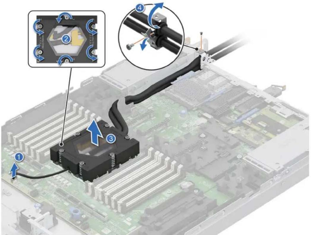
Figure 91. Removing the DLC module
- If required, replace the DLC blank.
- Align the DLC blank with the guide pin at the bottom of the chassis.
- Using a Phillips 1 screwdriver, tighten the screw to secure the DLC blank in place.
natural_image
3D mechanical assembly diagram showing a computer motherboard with a highlighted component and screwdriver (no text or symbols)Figure 92. Installing the DLC module blank
Next steps
If you are removing a faulty heat sink replace the DLC, if not remove the processor.
Installing the Direct Liquid Cooling(DLC)
Prerequisites
Never remove the heat sink from a processor unless you intend to replace the processor or heat sink. The heat sink is necessary to maintain proper thermal conditions.
- Follow the safety guidelines listed in the Safety instructions.
- Follow the procedure listed in the Before working inside your system.
Steps
- If required, remove the DLC module blank.
- Using the Phillips 1 screwdriver, loosen the screw to remove the DLC module.

natural_image
3D mechanical assembly diagram showing a computer motherboard with a highlighted component and screwdriver (no text or symbols)Figure 93. Removing the DLC module blank
- Align the DLC module with the standoff screws on the HPM board.
-
Using the Torx T20 screwdriver, tighten the captive nuts (12 in-lbf) on the DLC module in the order below:
a. In a random order, tighten the first nut three turns.
b. Tighten the nut diagonally opposite to the nut that you tighten first.
c. Repeat the procedure for the remaining two nuts.
d. Return to the first nut to tighten it completely.
e. Check all the nuts to ensure that they are firmly secured. -
Route the DLC tubes and secure it to the holder.
-
Route the DLC tubes to the rear of the system and align the rubber ring on the tubes with the ring holders.

NOTE: Follow the number labels on the DLC tubes and ring holders (1,2).
-
Tilt the ring holder close. Using a Phillips 1 screwdriver, tighten the captive screw on the DLC ring holder to secure it in place.
-
Connect the DLC leak sensor cable on the HPM board.

NOTE: The numbers on the image do not depict the exact steps. The numbers are for representation of a sequence.
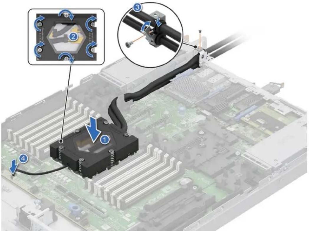
Figure 94. Installing the DLC module
Next steps
- Follow the procedure listed in the After working inside your system.
Removing the heat sink
Prerequisites
- Follow the safety guidelines listed in the Safety instructions.
- Follow the procedure listed in the Before working inside your system.

NOTE: The heat sink and processor are hot to touch for some time after the system has been powered off. Allow the heat sink and processor to cool down before handling them.
Steps
- Using a Phillips 2 screwdriver, loosen the captive screws on the heat sink in the numbered order that is mentioned on the heat sink assembly instructions label.
- Lift the heat sink away from the system.
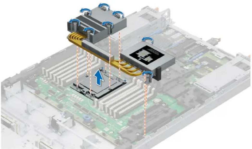
natural_image
3D illustration of a computer motherboard with cooling fans and CPU socket (no text or symbols)Figure 95. Removing the heat sink
Next steps
If you are removing a faulty heat sink replace the heat sink, if not remove the processor.
Removing the processor
Prerequisites
- Follow the safety guidelines listed in the Safety instructions.
- Follow the procedure listed in the Before working inside your system.
- Remove the heat sink module.

CAUTION: You may find the CMOS battery loss or CMOS checksum error that is displayed during the first instance of powering on the system after the processor or HPM board replacement which is expected. To fix this, go to setup option to configure the system settings.
Steps
- Using a T-20 Torx screwdriver, loosen the captive screws on the spring-loaded retention frame.

NOTE: Hold and rotate the retention frame until it is fully open.
natural_image
Isometric illustration of a mechanical component with blue arrows indicating rotation or movement, no text or symbols present.Figure 96. Releasing the retention frame
- Lift the rail frame by gripping the two blue tabs and rotate the rail frame upwards to a vertical position.

NOTE: Hold and rotate the rail frame until it is fully open.
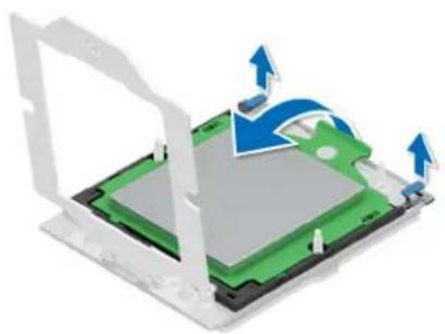
natural_image
3D diagram of a computer motherboard with arrows indicating movement or force (no text or symbols)Figure 97. Releasing the rail frame
- Slide the carrier frame together with the processor out from the rail frame by holding on to the green tab.
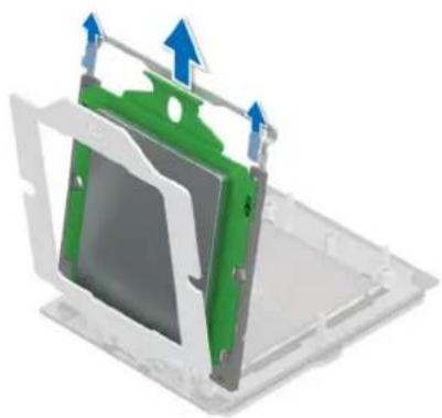
natural_image
3D diagram of a green and gray device housing with blue directional arrows indicating movement or force (no text or symbols)Figure 98. Removing the carrier frame with the processor
Next steps
Replace the processor.
Installing the processor
Prerequisites
- Follow the safety guidelines listed in the Safety instructions.
- Follow the procedure listed in the Before working inside your system.
- Remove the heat sink.
Steps
- Release the retention frame and rail frame. See step 1 and step 2 of the removing the processor.
- Insert the carrier frame with the processor into the rail frame until the carrier frame clicks in place with the rail frame.

NOTE: If there is a blank external cap in the rail frame, remove it by sliding it out from the rail frame.
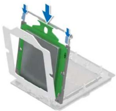
natural_image
3D diagram of a mechanical component with green and blue parts, showing assembly or assembly steps (no text or symbols)Figure 99. Inserting the carrier frame with the processor
- Close the rail frame down and press the left blue tab first to click in place. Then perform the same on the right blue tab.
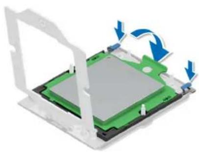
natural_image
3D diagram of a computer motherboard with green and gray components, showing blue directional arrows indicating rotation (no text or symbols)Figure 100. Closing the rail frame with the carrier frame
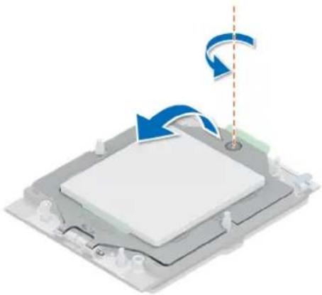
- Rotate and close the retention frame and tighten the captive screw.
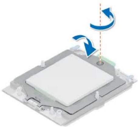
natural_image
3D diagram of a computer monitor with blue arrows indicating rotation and sound wave (no text or symbols)Figure 101. Securing the retention frame
Next steps
- Install the heat sink.
- Follow the procedure listed in After working inside your system.
Installing the heat sink
Prerequisites
Never remove the heat sink from a processor unless you intend to replace the processor or heat sink. The heat sink is necessary to maintain proper thermal conditions.
- Follow the safety guidelines listed in the Safety instructions.
- Follow the procedure listed in the Before working inside your system.
- The system supports different to types of heat sinks and the procedure to install them are similar.
Steps
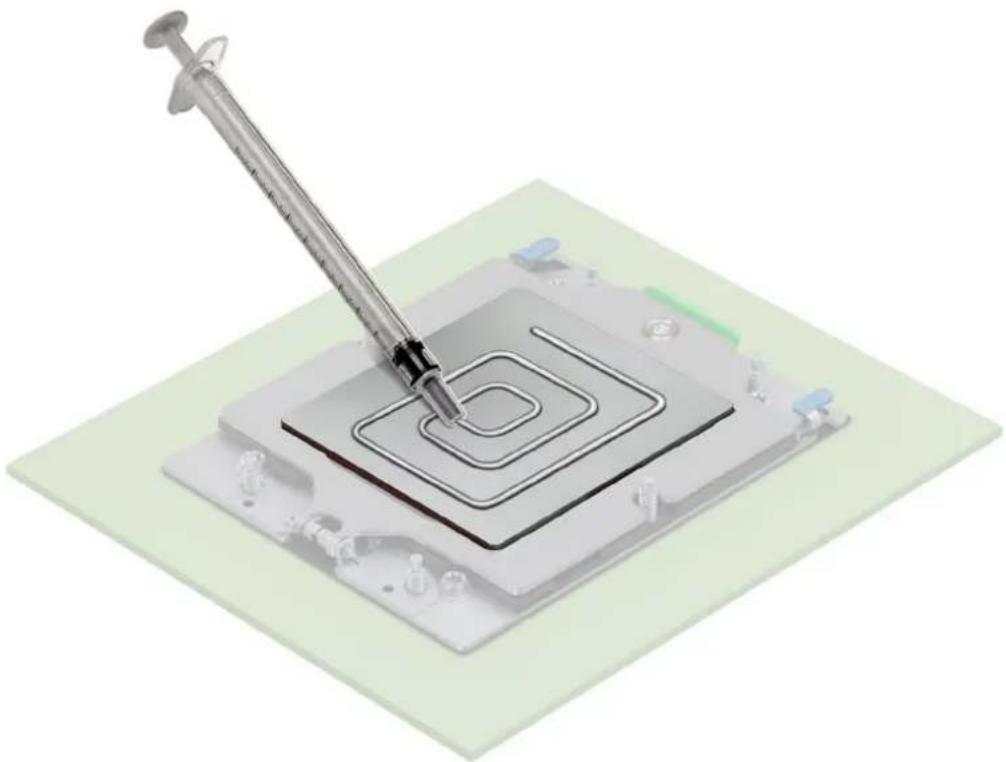
- If you are using an existing heat sink, remove the thermal grease on the heat sink by using the provided presaturated alcohol wipe.

NOTE: For a new heat sink, the thermal paste is preapplied to the heat sink. Remove the protective cover, and install the heat sink.
- Use the thermal grease syringe included with your processor kit to apply the grease in a thin quadrilateral spiral on the top of the processor.
natural_image
3D illustration of a syringe dispensing into a square microchip with concentric circuit patterns (no text or symbols)Figure 102. Applying thermal grease
NOTE: Applying too much thermal grease can result in excess grease coming in contact with and contaminating the processor socket.
NOTE: The thermal grease syringe is intended for single use only. Dispose of the syringe after you use it.
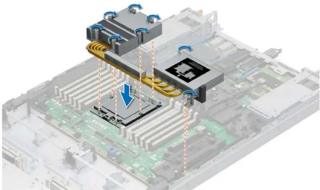
- Align the screws on the heat sink the guide pins on the CPU, and lower it down.
- Using the Phillips 2 screwdriver, secure the captive screws on the heat sink in the numbered order that is mentioned on the heat sink assembly instructions label.
natural_image
3D illustration of a computer motherboard with cooling fans and CPU socket, showing heat flow direction (no text or symbols)Next steps
- Follow the procedure listed in the After working inside your system.
Expansion card installation guidelines
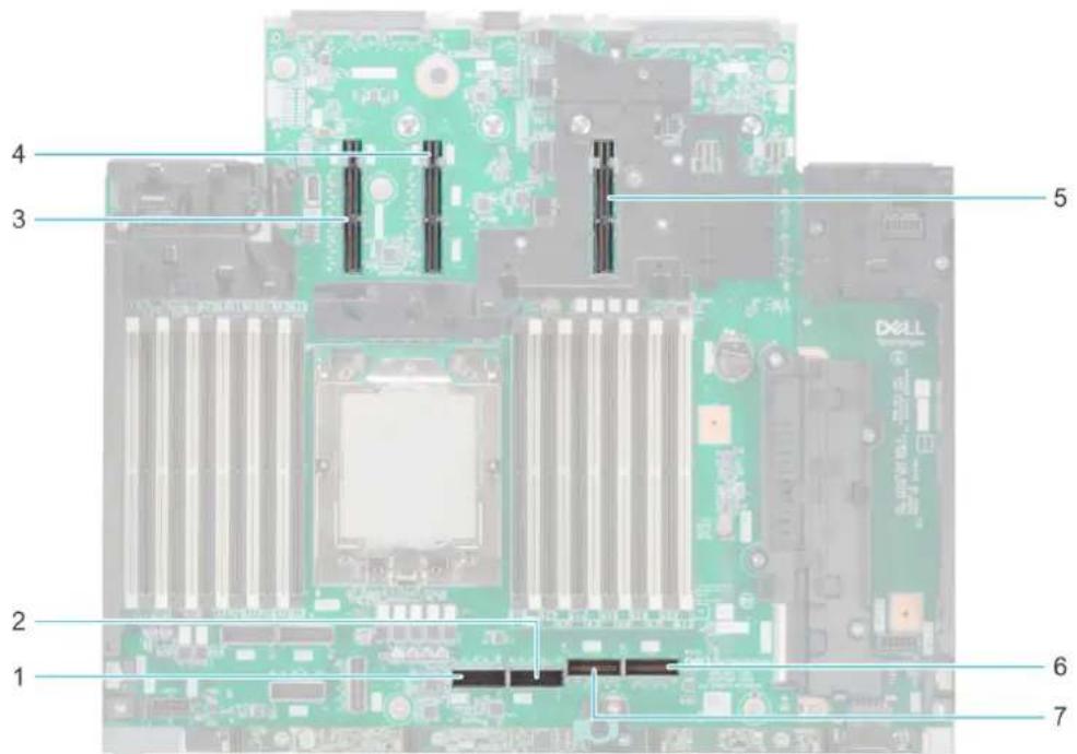
Figure 103. Expansion card riser slot connectors
- PCIe connector 5 (SL5_CPU 0)
- PCIe connector 6 (SL6_CPU 0)
- Riser 1 slot
- Riser 2 slot
- Riser 4 slot
- PCIe connector 8 (SL8_CPU 0)
- PCIe connector 7 (SL7_CPU 0)
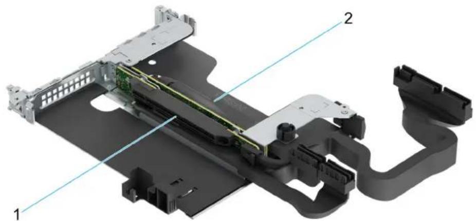
natural_image
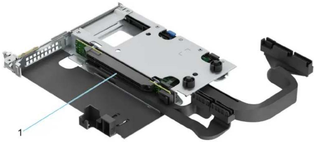
3D rendering of an electronic device chassis with visible components and wiring (no text or symbols)Figure 104. Riser 2k
- Slot 1
natural_image
3D mechanical assembly diagram showing internal components and labeled parts (no text or symbols present)Figure 105. Riser 2q
- Slot 1
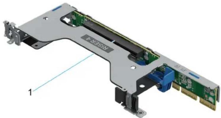
natural_image
3D diagram of a computer RAM card with visible internal components and labeled ports (no text or symbols beyond labels)Figure 106. Riser 4a
- Slot 4
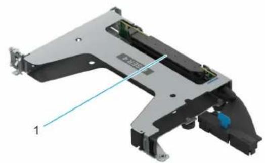
natural_image
3D mechanical component diagram showing a bracket with internal components and a labeled line (no text or symbols present)Figure 107. Riser 4b
- Slot 4

NOTE: The expansion-card slots are not hot-swappable.
The following table provides guidelines for installing expansion cards to ensure proper cooling and mechanical fit. The expansion cards with the highest priority should be installed first using the slot priority indicated. All the other expansion cards should be installed in the card priority and slot priority order.
Table 60. Expansion card riser configurations
| Riser Configurations (RC) | Expansion card risers | PCIe Slots Form factor Controlling | processor | Slot's electrical bandwidth/ physical connector | |
| RC2: R2R LP + R4 LP R2r 1 LP CPU0 PCIe Gen5 x16 (x16 | connector) | ||||
| 2 LP CPU0 PCIe Gen5 x16 (x16 | connector) | ||||
| OCP3 5 OCP3 CPU0 PCIe Gen5 x16 (4C+ | connector) | ||||
| BOSS 3 BOSS CPU0 PCIe Gen3 x4 (1C | connector) | ||||
| RC3: R2q FH + R4b FH R4b 4 FH CPU0 PCIe Gen5 x16 (x16 | connector) | ||||
| Riser Configurations (RC) | Expansion card risers | PCIe Slots Form factor Controlling | processor | Slot's electrical bandwidth/ physical connector | |
| R2q 1 FH CPU0 PCIe | Gen5 x16 (x16 | connector) | |||
| OCP3 5 OCP3 CPU0 | PCIe Gen5 x16 (4C+ | connector) | |||
| BOSS 3 BOSS CPU0 | PCIe Gen3 x4 (1C | connector) | |||
| RC4: R2r LP + R4a LP R4a 4 LP CPU0 PCIe Gen5 x16 (x16 | connector) | ||||
| RC 5 : R2k LP + R4a LP | R2k 2 Low profile + 2nd | OCP | Processor 0 PCIe Gen5 x16 (x16 connector) | ||
| R4a 1 Low profile Processor 0 PCIe Gen5 x16 (x16 | connector) | ||||
| BOSS 3 BOSS Processor 0 PCIe Gen3 x4 (1C | connector) | ||||
| OCP 5 OCP | Processor 0 PCIe Gen5 x16 (OCP | 4C+ connector) | |||
| RC6: R2s + R4a LP | R4a 4 LP CPU0 PCIe | Gen5 x16 (x16 | connector) | ||
| R2s | 1 LP CPU0 PCIe Gen5 x16 (x16 | connector) | |||
| OCP3 5 OCP3 CPU0 | PCIe Gen5 x16 (4C+ | connector) | |||
| BOSS 3 BOSS CPU0 | PCIe Gen3 x4 (1C | connector) | |||

NOTE: The system supports either Front I/O configuration (system with front risers) or Rear I/O configuration (system with rear risers).
Removing the expansion card risers
Prerequisites
- Follow the safety guidelines listed in the Safety instructions.
- Follow the procedure listed in the Before working inside your system.
- If applicable, disconnect the cables from the expansion card or HPM board.
Steps
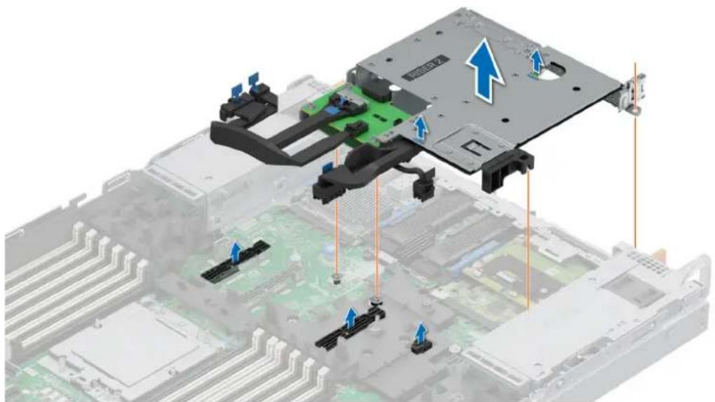
- For Riser 2k, disconnect the cables from the connectors and lift the expansion card riser to disengage it from the riser connector, and carefully remove it from the guide pin and cage guide hole.
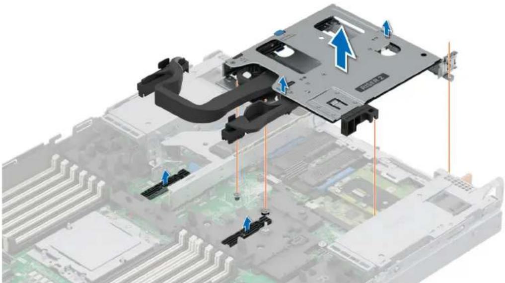
natural_image
3D illustration of an electronic device chassis with labeled components and arrows indicating assembly or movement (no text or symbols present)Figure 108. Removing the expansion card riser 2k (R2k)
- ForRiser 2s, disconnect the cables from the connectors and lift the expansion card riser to disengage it from the riser connector, and carefully remove it from the guide pin and cage guide hole. See cable routing section for more information about disconnecting the PERC cables.
natural_image
3D diagram of an electronic device with labeled components and directional arrows indicating assembly or movement (no readable text or symbols)Figure 109. Removing the expansion card riser 2s (R2s)
- For Riser 4a, ensure that the riser latch is unlocked. Lift the expansion card riser to disengage it from the connector and guide pin on the HPM board. Carefully remove the riser from the system.
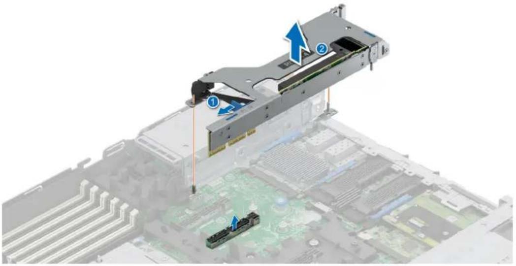
natural_image
3D diagram of a computer motherboard with labeled components and arrows indicating assembly or movement (no text or symbols present)Figure 110. Removing the expansion card riser 4a (R4a)
Next steps
Replace the expansion card risers.
Installing the expansion card risers
Prerequisites
- Follow the safety guidelines listed in the Safety instructions.
- Follow the procedure listed in the Before working inside your system.
- If removed, install the expansion cards into the expansion card risers.

- For Riser 2k, align the riser with the connector and guide pin, lower it into place, press to ensure that the riser is fully seated on the connector, and connect the cables to the connectors.

natural_image
3D diagram of a computer motherboard with labeled components and directional arrows indicating assembly or movement (no text or symbols present)Figure 111. Installing the expansion card riser 2k (R2k)
- ForRiser 2s, align the riser with the connector and guide pin, lower it into place, press to ensure that the riser is fully seated on the connector, and connect the cables to the connectors. See cable routing section for more information about connecting the PERC cables.

natural_image
3D diagram of an electronic device chassis with labeled components and directional arrows indicating assembly or movement (no readable text or symbols)Figure 112. Installing the expansion card riser 2s (R2s)
- For Riser 4a, align the expansion card riser with the connector and the riser guide pin on the HPM board. Lower the expansion card riser into place until the expansion card riser connector is fully seated in the connector. Press the touch points (indicated by blue line) to ensure proper engagement. Ensure that the riser latch is locked.
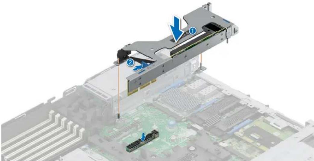
natural_image
3D diagram of a computer motherboard with labeled components (no text or symbols present)Figure 113. Installing the expansion card riser 4a (R4a)
Next steps
- If required, reconnect the cables to the expansion card or HPM board.
- Follow the procedure listed in After working inside your system.
Removing an expansion card from the expansion card riser
Prerequisites
- Follow the safety guidelines listed in the Safety instructions.
- Follow the procedure listed in Before working inside your system.
- If applicable, disconnect the cables from the expansion card.
- Remove the expansion card riser.
Steps
- For Riser 2k:
a. Lift the blue OCP latch to unlock the OCP card. Pull out and remove the OCP card from the riser.
b. Open the expansion card latches. Hold the expansion card by its edges and pull the card until the card edge connector disengages from the expansion card connector on the riser.
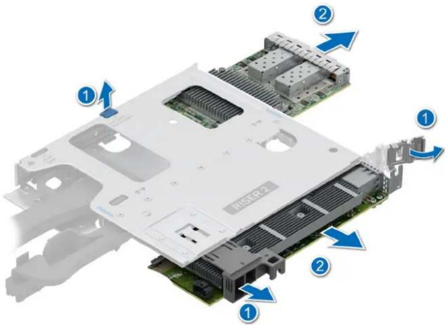
Figure 114. Removing an expansion card and OCP from the expansion card riser 2k
2. For Riser 4a:
a. Open the expansion card latches. Hold the expansion card by its edges and pull the card until the card edge connector disengages from the expansion card connector on the riser.
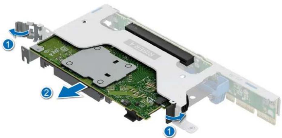
Figure 115. Removing expansion card from the expansion card riser 4a

If applicable, install an expansion card into the expansion card riser.
Installing an expansion card into the expansion card riser
Prerequisites
- Follow the safety guidelines listed in the Safety instructions.
- Follow the procedure listed in Before working inside your system.
- Remove the expansion card riser.
- If installing a new expansion card, unpack it and prepare the card for installation.

NOTE: For instructions, see the documentation accompanying the card.

- Open the expansion card latch.
- If installed, remove the PCIe blank from the risers.

NOTE: Store the PCIe blank for future use. PCIe blank must be installed in empty expansion card slots to maintain Federal Communications Commission (FCC) certification of the system. The blank also keep dust and dirt out of the system and aid in proper cooling and airflow inside the system.
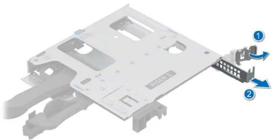
Figure 116. Removing the PCIe blank for the riser 2k
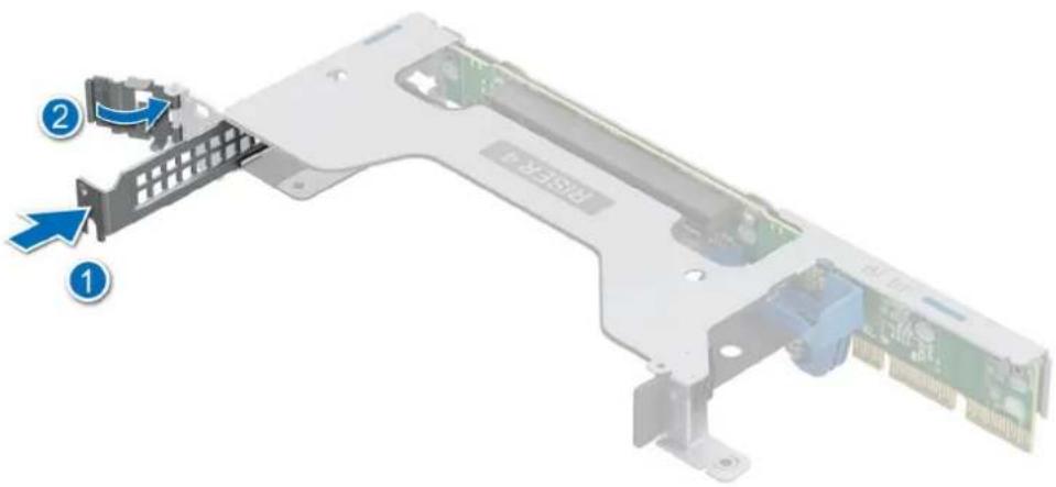
Figure 117. Removing the PCIe blank for the riser 4a
- For riser 2b:
a. Unlock the OCP latch. Slide the OCP card into the riser and lock the OCP latch.
b. Open the expansion card latches. Hold the card by the edges, and align the card edge connector with the expansion card connector on the riser.
c. Insert the card edge connector firmly into the expansion card connector until the card is fully seated.
d. Close the expansion card latches on both ends of the riser.
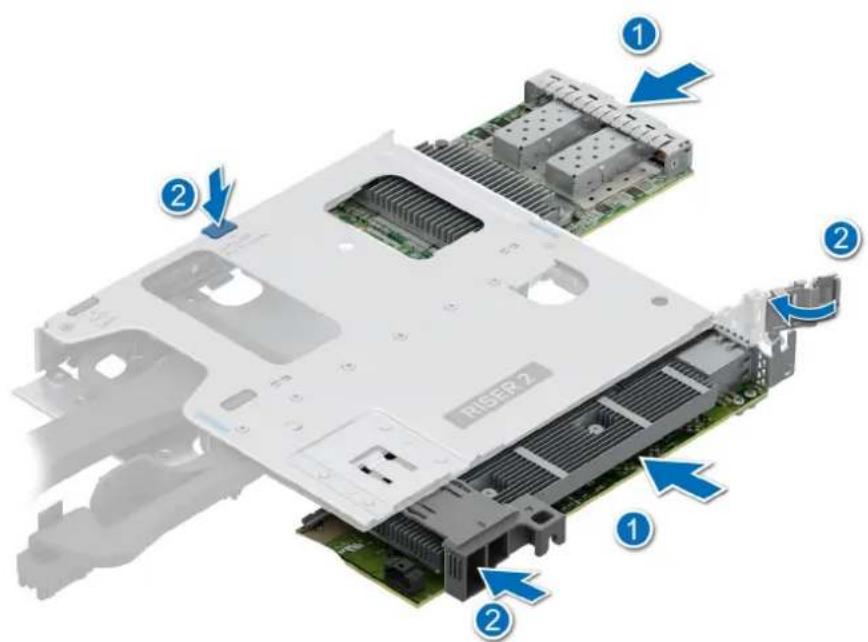
Figure 118. Installing an expansion card and OCP card into the riser 2k

a. Open the expansion card latches. Hold the card by the edges, and align the card edge connector with the expansion card connector on the riser.
b. Insert the card edge connector firmly into the expansion card connector until the card is fully seated.
c. Align and slide the card holder guides into the slots on the riser until seated.
d. Close the expansion card latches on both ends of the riser.

Figure 119. Installing an expansion card into the riser 4a
Next steps
- If applicable, connect the cables to the expansion card.
- Install the expansion card riser.
- Follow the procedure listed in the After working inside your system.
- Install any device drivers required for the card as described in the documentation for the card.
Module SSD M.2
natural_image
3D illustration of a computer RAM module with a USB flash drive and blue directional arrows indicating motion (no text or symbols)Figure 120. Retrait du support BOSS-N1 DC-MHS
natural_image
3D rendering of a black rectangular electronic device with heat exchangers and a blue circular arrow indicating rotation (no text or symbols)natural_image
3D illustration of a computer drive chassis with a green internal card and a blue arrow indicating a component (no text or symbols)Figure 123. Retrait du module SSD M.2 NVMe

natural_image
3D illustration of a computer drive chassis with a green card and a blue arrow indicating a component (no text or symbols on the card itself)Figure 124. Installation du module SSD M.2 NVMe
natural_image
3D rendering of a black rectangular electronic device with ventilation slots and blue circular arrows indicating rotation (no text or symbols)natural_image
Diagram of a mechanical device with two labeled parts (1 and 2), showing internal components and directional arrows (no text or symbols)Figure 127. Installation du support de carte BOSS-N1 DC-MHS
Module BOSS-N1 FDC-MHS en option
- Follow the safety guidelines listed in the Safety instructions.
- Follow the procedure listed in Before working inside your system.
- Remove the expansion card riser.
Steps
- Open the blue latch to disengage the BOSS-N1 DC-MHS module.
- Push the BOSS-N1 DC-MHS module towards the rear end of the system to disconnect from the connector on the HPM board.
- Slide the BOSS-N1 DC-MHS module out of the slot on the system.
natural_image
3D diagram of an open computer motherboard showing two labeled components (① and ②) with arrows indicating flow or movement, no readable text or symbols present.Figure 128. Removing the BOSS-N1 DC-MHS module
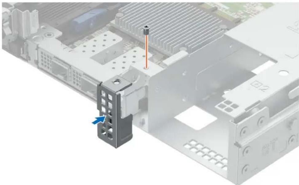
- If the BOSS-N1 DC-MHS module is not going to be replaced, install a filler bracket.
natural_image
Interior view of a computer motherboard showing a component being inserted, with a blue arrow indicating the direction (no text or symbols present)Figure 129. Installation of filler bracket
Next steps
- Replace the BOSS-N1 DC-MHS module.
Installing the BOSS-N1 DC-MHS module
Prerequisites
- Follow the safety guidelines listed in the Safety instructions.
- Follow the procedure listed in the Before working inside your system.
- Remove the expansion card riser.
Steps
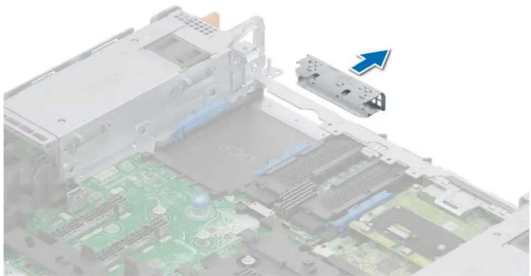
- If installed, remove the filler bracket.
NOTE: Store the filler bracket for future use. Filler brackets must be installed in empty expansion card slots to maintain Federal Communications Commission (FCC) certification of the system. The brackets also keep dust and dirt out of the system and aid in proper cooling and airflow inside the system.
natural_image
Interior view of a computer motherboard showing CPU socket and drive casing (no text or symbols visible)Figure 130. Removal of filler bracket
- Open the blue latch on the HPM board.
- Slide the BOSS-N1 DC-MHS module into the slot in the system.
- Push until the BOSS-N1 DC-MHS module is connected to the connector on the HPM board.
- Close the blue latch to lock the BOSS-N1 DC-MHS module to the system.
Figure 131. Installing the BOSS-N1 DC-MHS module
Next steps
- Install the expansion card riser.
- Follow the procedure listed in the After working inside your system.
Removing the rear OCP NIC card
Prerequisites
- Follow the safety guidelines listed in the Safety instructions.
- Follow the procedure listed in the Before working inside your system.
- Remove the expansion card riser.
Steps
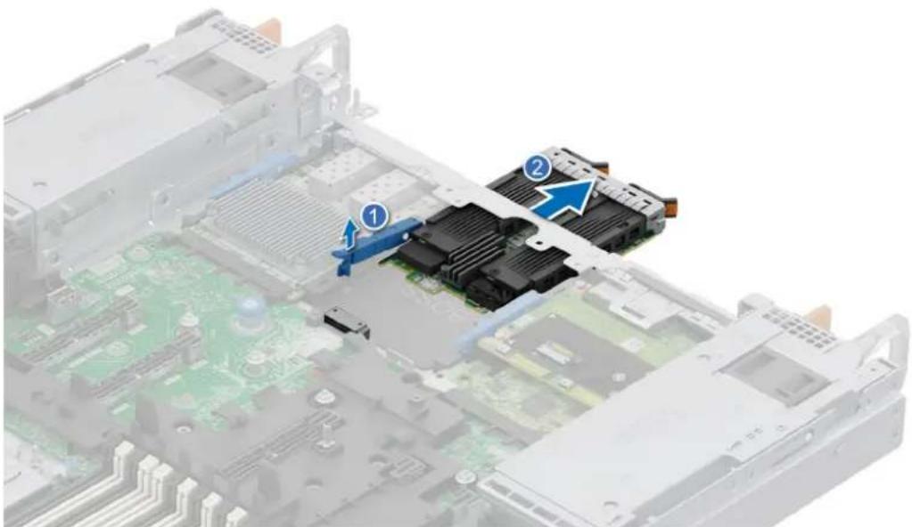
- Open the blue latch to disengage the OCP NIC card.
- Push the OCP NIC card towards the rear end of the system to disconnect from the connector on the HPM board.
- Slide the OCP NIC card out of the slot on the system.
natural_image
Interior view of a computer motherboard showing CPU socket, drive bays, and memory card (no text or symbols visible)Figure 132. Removing the OCP NIC card
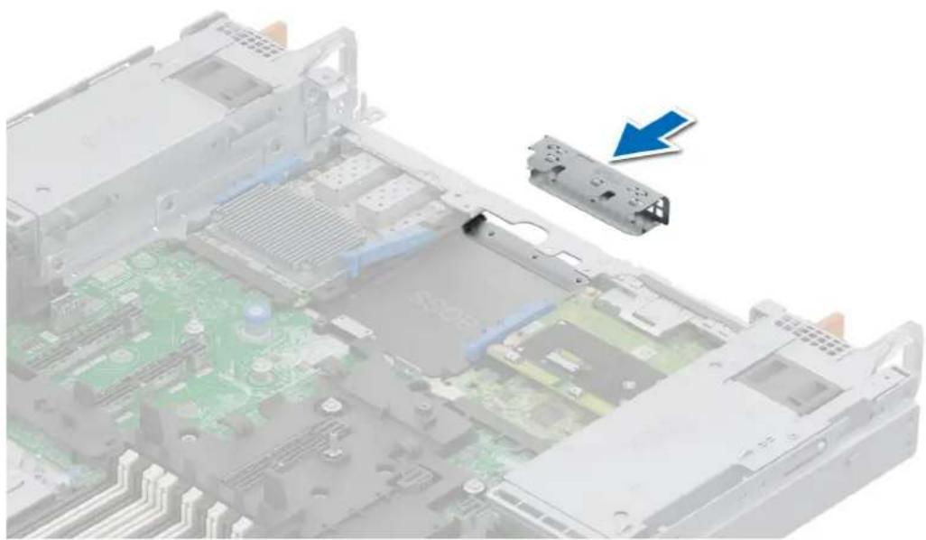
- If the OCP NIC card is not going to be replaced, install a filler bracket.
NOTE: You must install a filler bracket over an empty expansion card slot to maintain Federal Communications Commission (FCC) certification of the system. The brackets also keep dust and dirt out of the system and aid in proper cooling and airflow inside the system.

natural_image
Interior view of a computer motherboard showing CPU socket, drive bays, and circuit board (no text or symbols visible)Figure 133. Installation of filler bracket
Next steps
- Replace the OCP NIC card.
Installing the rear OCP NIC card
Prerequisites
- Follow the safety guidelines listed in the Safety instructions.
- Follow the procedure listed in the Before working inside your system.
- Remove the expansion card riser.

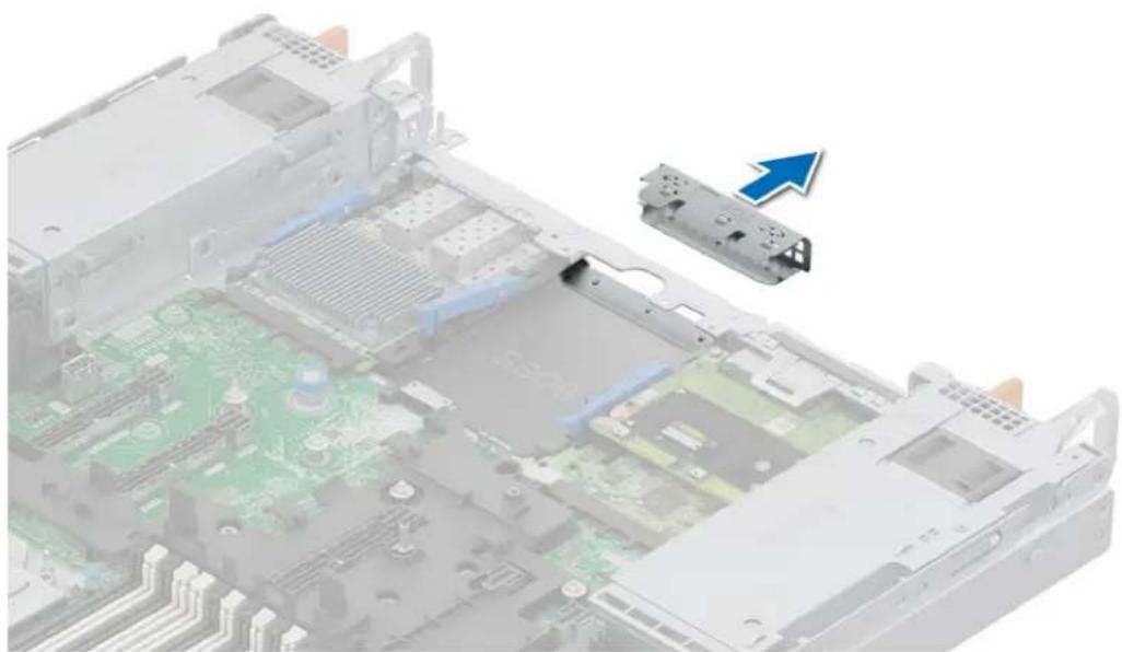
NOTE: Store the filler bracket for future use. Filler brackets must be installed in empty expansion card slots to maintain Federal Communications Commission (FCC) certification of the system. The brackets also keep dust and dirt out of the system and aid in proper cooling and airflow inside the system.
natural_image
Interior view of a computer motherboard showing CPU socket, drive bays, and circuit board (no text or symbols visible)Figure 134. Removal of filler bracket
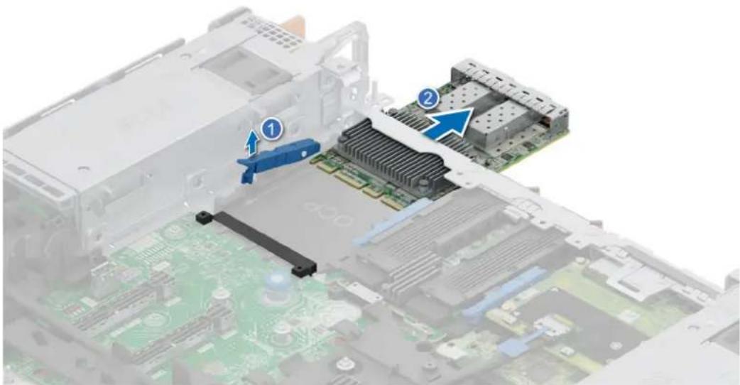
- Open the blue latch on the HPM board.
- Slide the OCP NIC card into the slot in the system.
- Push until the OCP NIC card is connected to the connector on the HPM board.
- Close the blue latch to lock the OCP NIC card to the system.

Figure 135. Installing the OCP NIC card
Next steps
- Route and connect the cables, taking care not to damage them.

NOTE: See cable routing section for more information.
- Install the expansion card riser.
- Follow the procedure listed in After working inside your system.
Removing the DC-SCM board
Prerequisites
- Follow the safety guidelines listed in the Safety instructions.
- Follow the procedure listed in the Before working inside your system.
- Remove the expansion card riser.

NOTE: Disconnect the Attic cable, see cable routing section.
Steps
- Open the blue latch to disengage the DC-SCM board.
- Push the DC-SCM board towards the rear end of the system to disconnect from the connector on the HPM board.
- Slide the DC-SCM board out of the slot on the system.
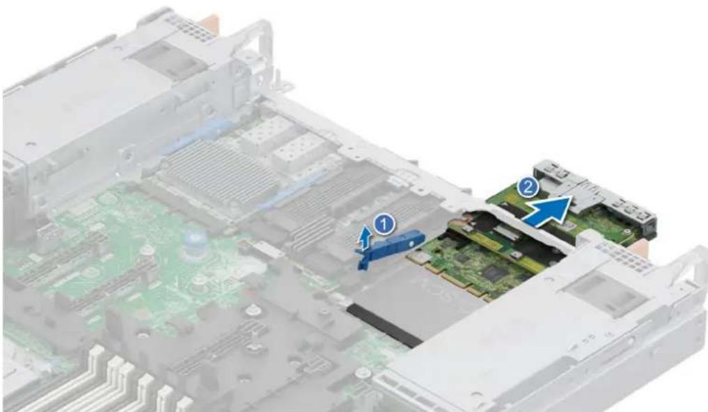
natural_image
Interior view of a computer motherboard showing two labeled components (① and ②) with no visible text or symbols beyond annotations.Figure 136. Removing the DC-SCM board
Next steps
- Remove the Attic card.
- Replace the DC-SCM board.
Installing the DC-SCM board
Prerequisites
- Follow the safety guidelines listed in the Safety instructions.
- Follow the procedure listed in the Before working inside your system.
- Remove the expansion card riser.
- Remove the attic board

NOTE: Disconnect the Attic cable, see cable routing section.

- Open the blue latch on the HPM board.
- Slide the DC-SCM board into the slot in the system.
- Push until the DC-SCM board is connected to the connector on the HPM board.
- Close the blue latch to lock the DC-SCM board to the system.

natural_image
Interior view of an open computer motherboard showing internal components and a close-up of the circuit board (no text or symbols visible)Figure 137. Installing the DC-SCM board
Next steps
- Install the Attic board.

NOTE: Connect the Attic cable, see cable routing section.
- Install the expansion card riser.
- Power on the system.
- Ensure that you perform the following steps:
a. Use the Easy Restore feature to restore the BIOS and Service Tag. See the Restoring the system using the Easy Restore feature section.
b. If the service tag is not backed up in the backup flash device, enter the system service tag manually. See the Manually update the Service Tag by using System Setup section.
c. Install BIOS and iDRAC version updates, Diagnostic, and OS Drivers Pack and OS Collector.
d. Re-enable the Trusted Platform Module (TPM). See the Upgrading the Trusted Platform Module section.
- Follow the procedure listed in After working inside your system.
Carte Attic
Removing the Attic board
Prerequisites
- Follow the safety guidelines listed in the Safety instructions.
- Follow the procedure listed in the Before working inside your system.
- Remove the expansion card riser.
- Remove the DC-SCM board.
Steps
-
Using the Phillips 1 screwdriver, loosen the captive screws securing the attic board to the DC-SCM board.
-
Tilt and lift the Attic board from the DC-SCM guide pins.
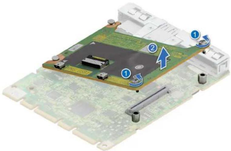
Figure 138. Removing the Attic board
Next steps
- Replace the Attic board.
Installing the Attic board
Prerequisites
- Follow the safety guidelines listed in the Safety instructions.
- Follow the procedure listed in the Before working inside your system.
- Remove the expansion card riser.
- Remove the DC-SCM board.

- Align the Attic board at an angle with the guide pins on the DC-SCM board.
- Press until the Attic board is connected to the connector on the DC-SCM board.
- Using a Phillips 1 screwdriver, tighten the captive screws.

Figure 139. Installing the Attic board
Next steps
- Install the DC-SCM board.
- Install the expansion card riser.
- Follow the procedure listed in After working inside your system.
DELL Technologies
Figure 140. Restauration facile
Removing the internal USB card
Prerequisites

CAUTION: To avoid interference with other components in the server, the maximum permissible dimensions of the USB memory key are 15.9 mm wide x 57.15 mm long x 7.9 mm high.
- Follow the safety guidelines listed in the Safety instructions.
- Follow the procedure listed in the Before working inside your system.
- Remove the expansion card riser.
Steps
Lift the internal USB card to disconnect from the connector on the HPM board.
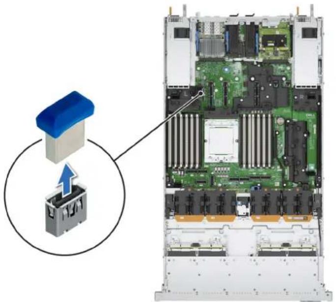
natural_image
Interior view of a server rack with an open circuit board and a blue-labeled component (no text or symbols visible)Figure 141. Removing the internal USB card
Next steps
- Replace the internal USB card.
Installing the Internal USB card
Prerequisites
- Follow the safety guidelines listed in the Safety instructions.
- Follow the procedure listed in the Before working inside your system.
- Remove the expansion card riser.
Steps
Align the internal USB card with the USB port on the HPM board and press firmly until it is properly seated.
NOTE: For information about the exact location of USB on HPM board, see HPM board jumpers and connectors section.
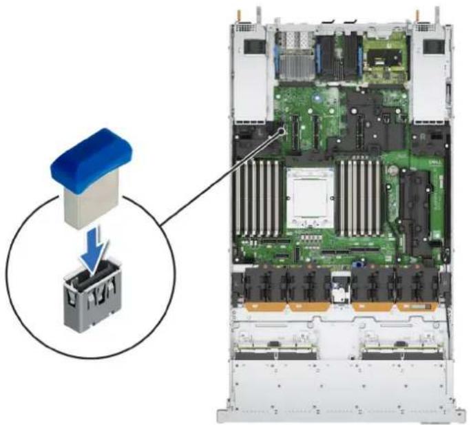
natural_image
Interior view of a server rack with an open circuit board and a blue-labeled component (no text or symbols visible)Figure 142. Installing the internal USB card
Next steps
- Install the expansion card riser.
- Follow the procedure listed in After working inside your system.
- While booting, press F2 to enter System Setup and verify that the system detects the USB memory key.
Batterie du système
Replacing the system battery
Prerequisites
WARNING: There is a danger of a new battery exploding if it is incorrectly installed. Replace the battery only with the same or equivalent type that is recommended by the manufacturer. Discard used batteries according to the manufacturer's instructions. See the Safety instructions that came with your system for more information.
- Follow the safety guidelines listed in the Safety instructions.
- Follow the procedure listed in the Before working inside your system.
- If applicable, disconnect the power or data cables from the expansion cards.
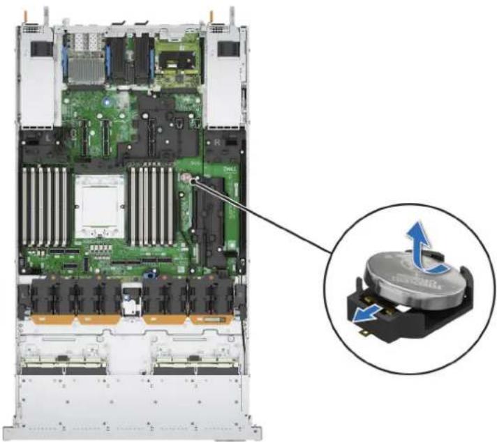
Steps
- Press and hold the battery socket retention latch, for the battery to pop out.

NOTE: If the battery does not pop out, then lift it out of the socket.
Figure 143. Removing the system battery
natural_image
Internal view of a server rack with visible CPU socket and drive mechanism (no text or symbols)-
To install a new system battery, hold the battery with the positive side facing up at an angle and slide it under the battery holder socket latch.
-
Press the battery into the connector until it snaps into place.
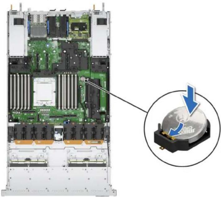
natural_image
Internal view of a server rack with an inset showing a CD-ROM drive (no text or symbols visible)Figure 144. Installing the system battery
Next steps
- If applicable, connect the cables to one or more expansion cards.
- Follow the procedure listed in After working inside your system.
- Confirm that the battery is operating properly, by performing the following steps:
a. Enter the System Setup, while booting, by pressing F2.
b. Enter the correct time and date in the System Setup Time and Date fields.
c. Exit the System Setup.
d. To test the newly installed battery, check the time and date at least an hour after installing the battery.
e. Enter the System Setup and if the time and date are still incorrect, see Getting help section.
natural_image
3D rendering of an open computer motherboard with labeled components (no text or symbols beyond numbered annotations)natural_image
3D rendering of an electronic device chassis with labeled components (no readable text or symbols)natural_image
3D illustration of a server rack with a hand inserting a device into the frame, showing blue directional arrows (no text or symbols)natural_image
3D rendering of a server rack with an open drive component and a blue arrow pointing to it (no text or symbols visible)natural_image
3D rendering of a server rack with an open drive and a blue arrow indicating a loading or download action (no text or symbols present)natural_image
3D rendering of a server rack with an attached drive component and a blue arrow indicating a specific part (no text or symbols present)Removing the HPM board
Prerequisites

CAUTION: If you are using the Trusted Platform Module (TPM) with an encryption key, you may be prompted to create a recovery key during program or System Setup. Be sure to create and safely store this recovery key. If you replace this HPM board, you must supply the recovery key when you restart your system or program before you can access the encrypted data on your drives.
- Follow the safety guidelines listed in the Safety instructions.
- Follow the procedure listed in the Before working inside your system.
- Remove the following components:
a. Cooling fans
b. Side wall bracket
c. Middle bracket
d. Memory modules
e. Expansion card risers
f. Heat sink module
g. OCP (if installed)
h. BOSS-N1 DC-MHS
i. DC-SCM
j. Internal USB memory key (if installed)
k. Power supply units (PSU)
I. Disconnect all the cables from the HPM board and make note of all the cable connections.

CAUTION: Take care not to damage the system identification button while removing the HPM board from the system.

NOTE: Do not lift the HPM board by holding a memory module, processor, or other components.
Steps
- Using the HPM board holder and plunger, slide the HPM board towards the front of the system.
- Securely hold the holder and plunger to carefully lift the HPM board out of the chassis.
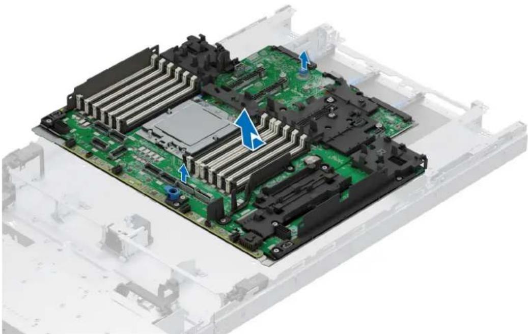
natural_image
3D rendering of a computer motherboard with visible CPU socket and circuit board (no text or symbols)Figure 151. Removing the HPM board
Next steps
- Install the HPM board.
Installing the HPM board
Prerequisites
- Follow the safety guidelines listed in the Safety instructions.
- Follow the procedure listed in Before working inside your system.
- If you are replacing the HPM board, remove all the components that are listed in the removing the HPM board section.
Steps
- Unpack the new HPM board assembly.

NOTE: Do not lift the HPM board by holding a memory module, processor, or other components.

CAUTION: Take care not to damage the system identification button while placing the HPM board into the chassis.
- Holding the HPM board holder and plunger, align and lower the HPM board into the system.
- Slide the HPM board towards the rear of the chassis until the connectors are firmly seated in the slots.
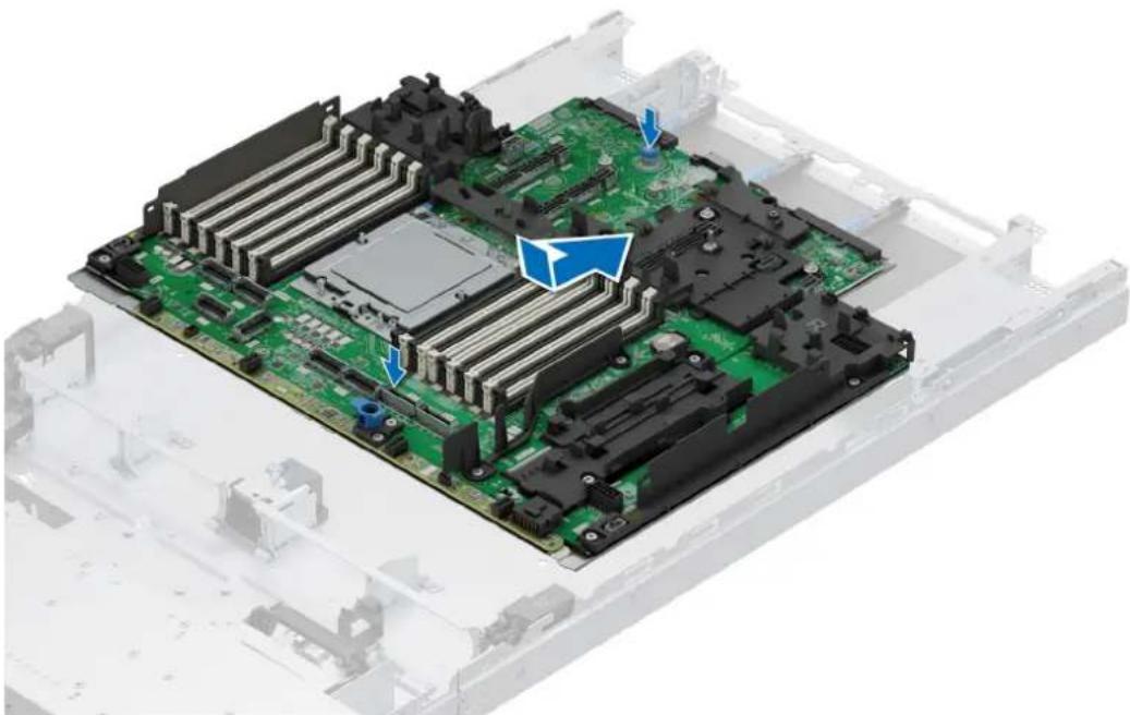
natural_image
3D rendering of a computer motherboard with visible CPU socket and cooling fins (no text or symbols)Figure 152. Installing the HPM board
Next steps
- Replace the following components:
a. Internal USB memory key (if removed)
b. OCP card (if removed)
c. BOSS-N1 DC-MHS
d. DC-SCM
e. Heat sink module
f. Memory modules
g. Expansion card risers
h. Middle bracket
i. Side wall bracket
j. Cooling fans
k. Power supply units (PSU)
- Reconnect all cables to the HPM board.

NOTE: Ensure that the cables inside the system are routed along the chassis wall and secured using the cable securing bracket.
- Follow the procedure listed in After working inside your system.
panneau de commande
natural_image
Close-up of a server rack with an attached electrical connector and a magnified inset showing the cable connection (no text or symbols visible)Removing the Left Control Panel (LCP) - Secondary
Prerequisites
- Follow the safety guidelines listed in the Safety instructions.
- Follow the procedure listed in the Before working inside your system.
- Remove the system cover.
- Remove the drive backplane cover.
- Remove the side wall bracket.
- Remove the expansion card riser
Steps
- For the EDSFF E3.S Gen5 NVMe configuration, disconnect the LCP cable from the connector on the HPM board.
- Using the Phillips 1 screwdriver, remove the screws that secure the LCP and the bracket.
- Remove the bracket away from the system.
- Holding the cable, slide the LCP out of the system.
NOTE: Observe the routing of the cable as you remove the LCP from the system.

Figure 155. Removing the Left Control Panel (LCP) - Secondary of EDSFF E3.S Gen5 configuration
- For the 2.5-inch Universal SSD configuration, disconnect the LCP cable from the connector on attic card.
- Using the Phillips 1 screwdriver, remove the screws that secure the LCP.
- Release the cable from the clip. While holding the cable, slide the LCP out of the system.
Figure 156. Removal of the Left Control Panel (LCP) - Secondary of 2.5-inch Universal SSD configuration
Next steps
- Replace the Left Control Panel (LCP) - Secondaryl.
Installing the Left Control Panel (LCP) - Secondary
Prerequisites
- Follow the safety guidelines listed in the Safety instructions.
- Follow the procedure listed in the Before working inside your system.
- Remove the drive backplane cover.
- Remove the side wall bracket.
- Remove the expansion card riser.
Steps
- For the EDSFF E3.S Gen5 NVMe configuration, align and slide the LCP panel in the slot on the system.
- Using the Phillips 1 screwdriver, tighten the screws to secure the LCP and the bracket to the system.
- Route the LCP cable through the side wall of the system. Align and slide the LCP cable cover in the slot on the system.

NOTE: Route the cable properly to prevent the cable from being pinched or crimped.
- Connect the LCP cable to the connector on the attic card.

Figure 157. Installing the Left Control Panel (LCP) - Secondary for EDSFF E3.S Gen5 configuration
- For the 2.5-inch Universal SSD configuration, align and slide the LCP in the slot on the system.
- Using the Phillips 1 screwdriver, tighten the screws to secure the LCP.
- Route the LCP cable through the side wall of the system. Align and slide the LCP cable under the bracket.

NOTE: Route the cable properly to prevent the cable from being pinched or crimped.
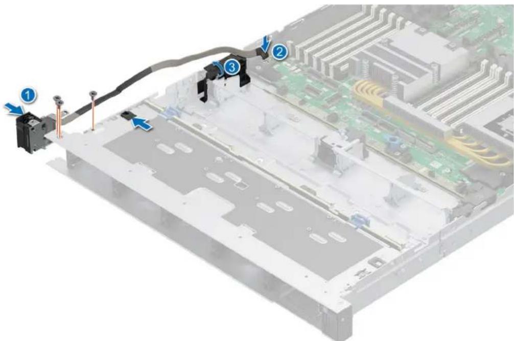
Figure 158. Installing the Left Control Panel (LCP) - Secondary for 2.5-inch Universal SSD configuration
- Fasten the cable with the clip.
- Connect the LCP cable to the connector on the HPM board.
Next steps
- Install the side wall bracket.
- Install the drive backplane cover.
- Install the expansion card riser
- Follow the procedure listed in After working inside your system.
natural_image
Close-up of a computer monitor front panel showing control buttons and a USB port (no readable text or symbols)Dell.com/support PER6715

Scan for quick access to self-service videos and documentation for this device.
Figure 166. QRL (Quick Resource Locator) pour système PowerEdge R6715
- Dell PowerEdge R6715
- Steps
- Next steps
- Figure 55. Fond de panier SAS/SATA de 3,5 pouces\*
- Étapes suivantes
- Installing a memory module
- Prerequisites
- Removing the Direct Liquid Cooling(DLC)
- Installing the Direct Liquid Cooling(DLC)
- Removing the heat sink
- Removing the processor
- Installing the processor
- Installing the heat sink
- Expansion card installation guidelines
- Removing the expansion card risers
- Installing the expansion card risers
- Removing an expansion card from the expansion card riser
- For Riser 4a:
- Installing an expansion card into the expansion card riser
- Module SSD M.2
- Module BOSS-N1 FDC-MHS en option
- Installing the BOSS-N1 DC-MHS module
- Removing the rear OCP NIC card
- Installing the rear OCP NIC card
- Removing the DC-SCM board
- Installing the DC-SCM board
- Carte Attic
- Removing the Attic board
- Installing the Attic board
- DELL Technologies
- Removing the internal USB card
- Installing the Internal USB card
- Batterie du système
- Replacing the system battery
- Removing the HPM board
- Installing the HPM board
- panneau de commande
- Removing the Left Control Panel (LCP) - Secondary
- Installing the Left Control Panel (LCP) - Secondary
Brand : DELL
Model : PowerEdge R6715
Category : Server