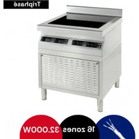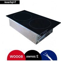
KTI2 - Hob Adventys - Free user manual and instructions
Find the device manual for free KTI2 Adventys in PDF.


User questions about KTI2 Adventys
0 question about this device. Answer the ones you know or ask your own.
Ask a new question about this device
Download the instructions for your Hob in PDF format for free! Find your manual KTI2 - Adventys and take your electronic device back in hand. On this page are published all the documents necessary for the use of your device. KTI2 by Adventys.
USER MANUAL KTI2 Adventys
natural_image
Technical line drawings of three electronic device modules with circular cutouts and internal components (no text or symbols)Chère cliente, cher client,
natural_image
Symbol of a trash bin with crossed lines indicating no waste or discharge (no text or labels)natural_image
Simple line drawing of a rectangular frame with rounded corners and internal lines (no text or symbols)natural_image
Exterior view of a modern ADVENTS industrial control unit with visible ports and wiring (no readable text beyond branding)natural_image
Diagram of an internal computer drive showing internal grid and ports (no text or labels)Arrivée d'air frais
text_image
INDUC HIP-Sortie d'air chaud
natural_image
Line drawing of three stacked electronic equipment units with internal circuitry (no text or symbols)text_image
Internal view of a server rack with labeled ports and connectors, showing red arrows pointing to ports 1 and 2.natural_image
Two-panel image showing a server rack with green connectors and a close-up of an electrical enclosure containing red components (no visible text or symbols)natural_image
Two views of an industrial electrical enclosure with visible wiring and components, no text or symbols present.Professional induction hob KTi2
EN
User's guide For your induction hob

natural_image
Technical line drawings of three electronic equipment modules with circular cutouts and internal components (no text or symbols)Dear Customer,
We would like to congratulate you on the purchase of your ADVENTYS product.
This one has been manufactured according to the very latest developments, using modern, safe electrical and electronic components.
Please take the time to read this user's guide before using this appliance.
Thank you for your confidence in our products.
Contents
Technical information 18
Declaration of Compliance and disposal of appliance 18
Integrate your hob 19
Using your induction hob 28
How the hob works 21
Cookware recommended 29
Small problems and their remedies 30
Garantiee 31
Technical specifications
| Model: | KTi2 |
| Name: | Integrated induction hob |
| Matérials: | Stainless steel and EZ |
| Power: | 8000 / 12000W |
| Electricity supply: | Three phase 400V (Works between 320 and 450V / 40 and 70Hz) |
| Current: | 12A per phases for KTi2 800020A per phases for KTi2 12000 |
| Controls: | Knob and 2 digits power display for each zones. |
| Dimensions of the vitroceramic glass: | W 360 X D 690 X H 6 mm or W 325 X D 600 X H 6 mm |
| Dimensions of the inductors: | 230 mm |
| Maximun weight allowed on the appliance: | 30 kg |
Compliance and waste statement
CE
This product complies with current EU directives. We certify this in the EU compliance statement. We can send you a copy of the compliance statement in question if required.
The packing materials in which this appliance is packed are recyclable. Please recycle them by disposing of them in the appropriate containers at your local facility. In so doing, you will be making a n to the protection of the environment.
At the end of its useful life, the appliance to be scrapped must be destroyed in accordance with the applicable national regulations that govern the elimination and recycling of waste.
We recommend you contact a company that specialises in waste disposal.
natural_image
Simple line drawing of a trash bin with no text or symbolsWARNING :
To avoid all risks associated with the destruction of the appliance, ensure that it is disconnected from themains and that the mains cable is removed.
PLEASE NOTE!
When destroying the appliance, local rules and the applicable regulations in your country or geographical
zone must be adhered to.
Product integration
Mechanical installation for 360 x 690 vitroceramic :
- 1 - Carry out the cut in the top respecting the drawing (366 +4/-0 x 696 +4/-0).
- 2 - Set the frame under your counter top.
- 3 - Insert the kit inside the cut and adjust the 4 screws in order to obtain the top of the furniture and the top of the vitroceramic glass at the same level.
- 4 - Remove the kit.
- 5 - Deposit the thermal high-strength glue on the 4 supports.
- 6 - Insert second time the kit inside the cut with better centering.
- 7 - Press the kit until to touch the 4 screws.
- 8 - Clean the surplus of glue to have no overflowing above the upper plan.
- 9 - Leave the glue to get dry without warming the integrated kit.
-10 - Make the seal ( food quality).
-11 - Leave the seal to get dry without warming the integrated kit.
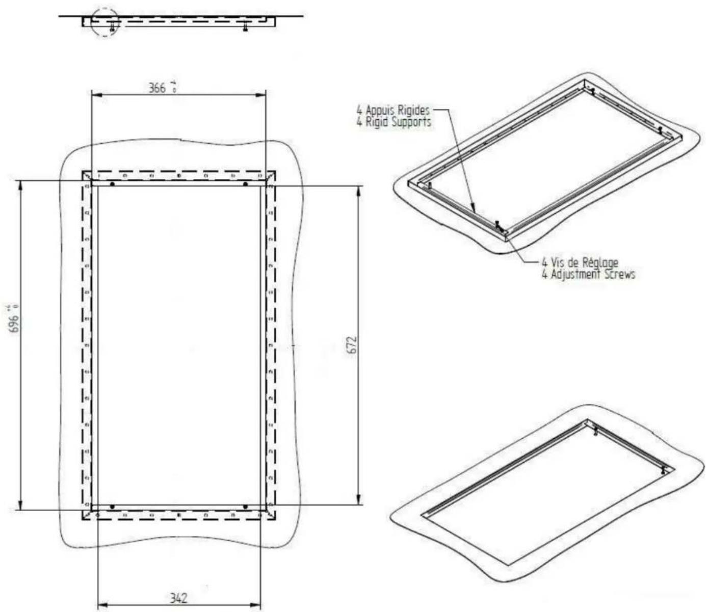
text_image
366 696 672 342 4 Appuis Rigides 4 Rigid Supports 4 Vis de Réglage 4 Adjustment ScrewsProduct integration
Mechanical installation for 325 x 600 vitroceramic :
- 1 - Carry out the cut in the top respecting the drawing (331 +4/-0 x 606 +4/-0).
- 2 - Set the frame under your counter top.
- 3 - Insert the kit inside the cut and adjust the 4 screws in order to obtain the top of the furniture and the top of the vitroceramic glass at the same level.
- 4 - Remove the kit.
- 5 - Deposit the thermal high-strength glue on the 4 supports.
- 6 - Insert second time the kit inside the cut with better centering.
- 7 - Press the kit until to touch the 4 screws.
- 8 - Clean the surplus of glue to have no overflowing above the upper plan.
- 9 - Leave the glue to get dry without warming the integrated kit.
-10 - Make the seal ( food quality).
-11 - Leave the seal to get dry without warming the integrated kit.
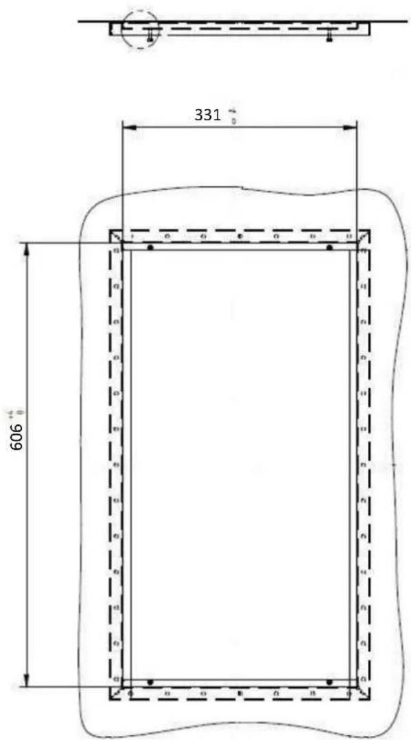
text_image
331 606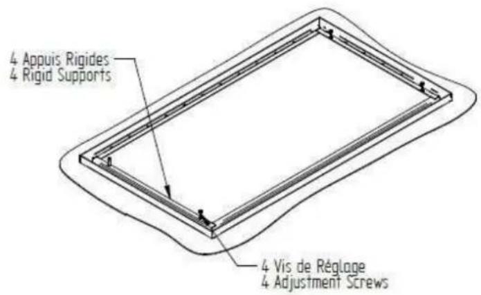
text_image
4 Appuis Rigides 4 Rigid Supports 4 Vis de Réglage 4 Adjustment Screws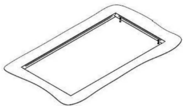
natural_image
Simple line drawing of a rectangular frame with rounded corners and internal lines, no text or symbols present.Product integration
Control panel installation (capacitives touches or knobs) :
1)Realize a cut out following this plan :
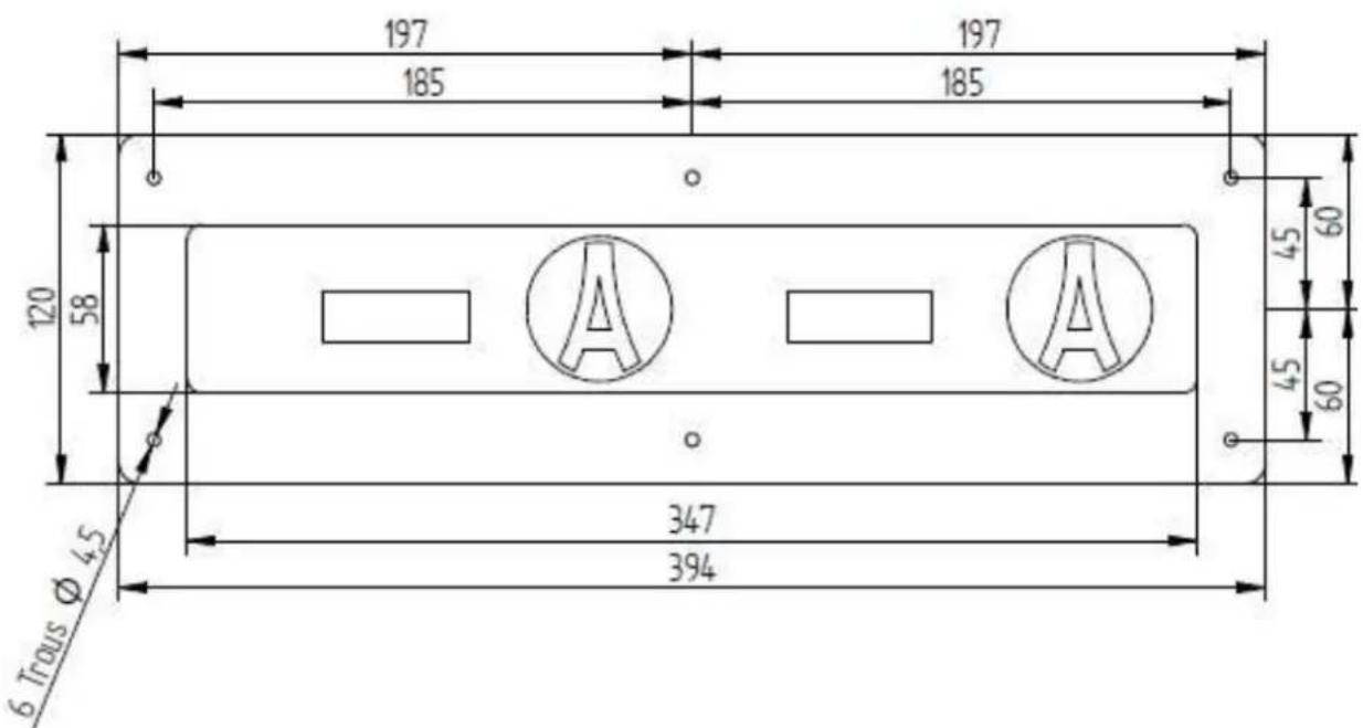
text_image
197 185 197 185 120 58 45 60 45 60 347 394 6 Trous Ø 4.52) Add a silicone joint under the control panel.
3) Insert the control panel into the cut out.
4) Fix the control panel by tightening the bolts
Product integration
DUO COMPACT generator
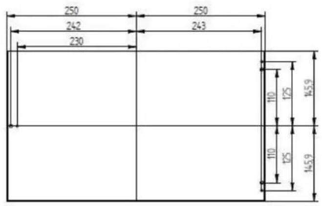
text_image
250 242 230 250 243 110 125 145.9 110 125 145.9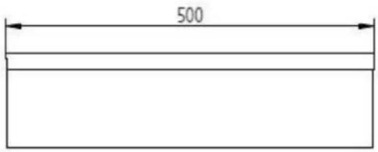
text_image
500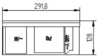
text_image
291,8 HV~ Out A 007 128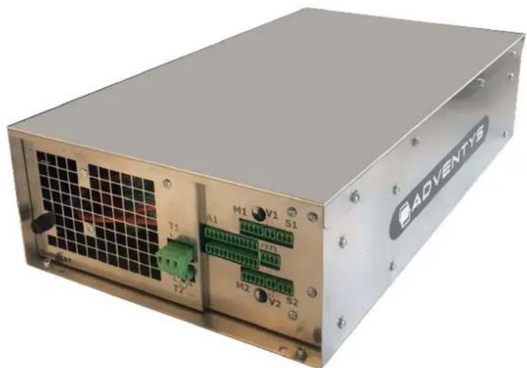
natural_image
Exterior view of a modern ADVENTIS industrial control unit with visible ports and wiring (no readable text beyond branding)Product integration
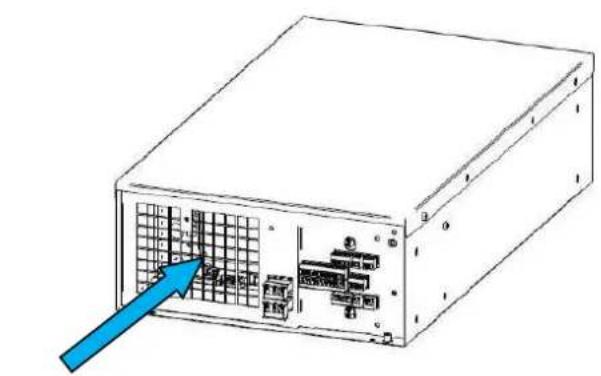
natural_image
Diagram of an internal server unit with a blue arrow pointing to the internal grid panel (no text or symbols present)Fresh air Inlet
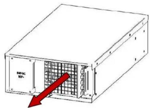
text_image
INDUC HIP-Hot Air Outlet
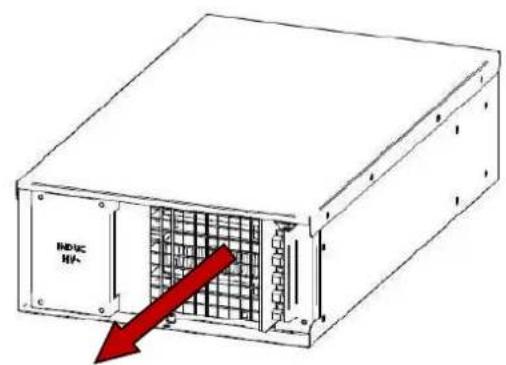
DUO COMPACT generator is equipped with its own system of internal ventilation.
(!) WARNING
The cooking furniture must be equipped with an air inlet filtered about 100 x 200mm and with an extraction of hot air to allow a good aeraulics of the set up.
Installation tips :
DUO COMPACT generator is empilables for an important space saving.
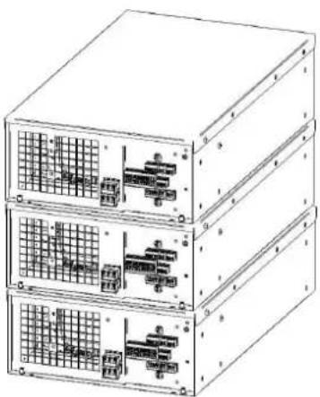
natural_image
Line drawing of three stacked electronic equipment units with internal circuitry (no text or symbols)Product integration
Inductor to deported connexions
Knob + display version
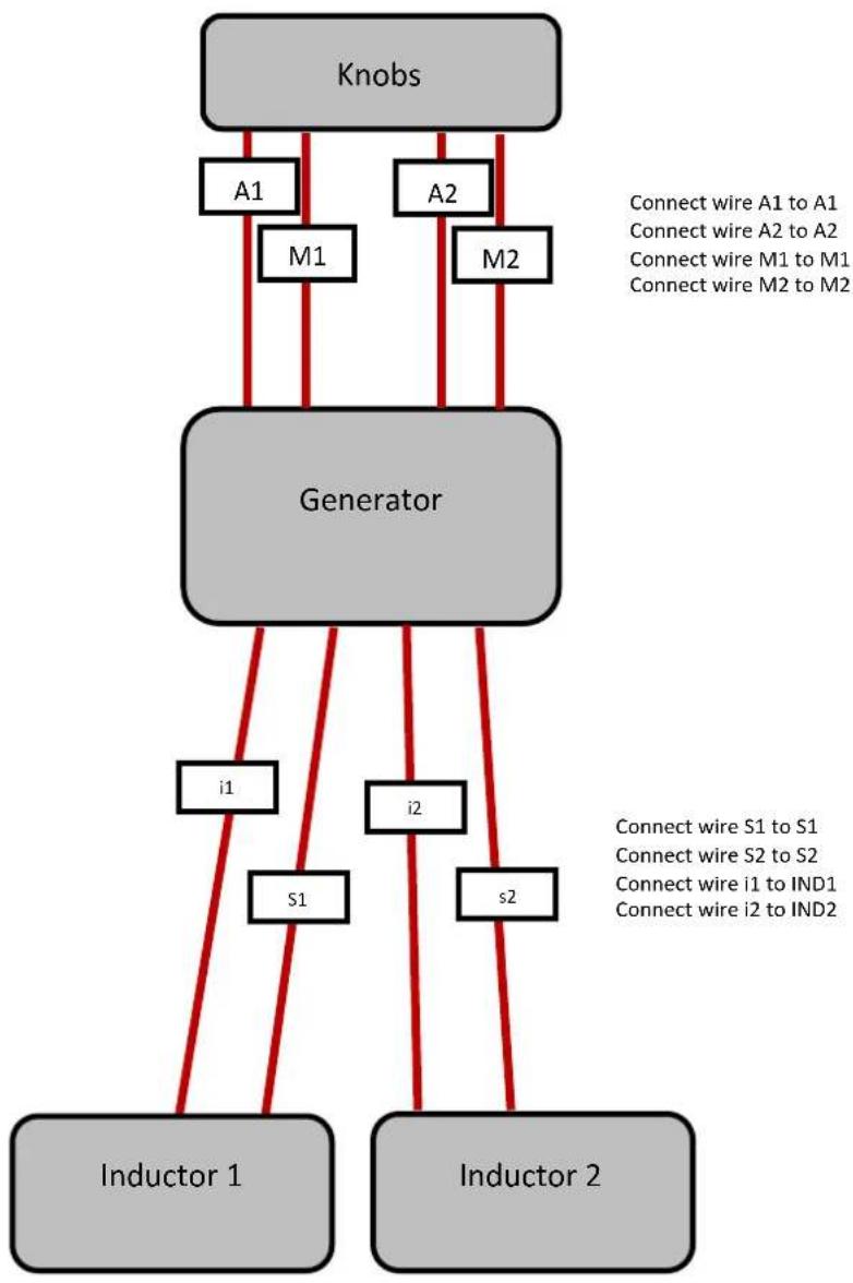
flowchart
graph TD
    A["Knobs"] --> B["Generator"]
    B --> C["Inductor 1"]
    B --> D["Inductor 2"]
    B --> E["i1"]
    B --> F["i2"]
    B --> G["s1"]
    B --> H["s2"]
    A --> I["A1"]
    A --> J["A2"]
    A --> K["M1"]
    A --> L["M2"]
    style A fill:#ccc,stroke:#333
    style B fill:#ccc,stroke:#333
    style C fill:#ccc,stroke:#333
    style D fill:#ccc,stroke:#333
    style E fill:#ccc,stroke:#333
    style F fill:#ccc,stroke:#333
    style G fill:#ccc,stroke:#333
    style H fill:#ccc,stroke:#333
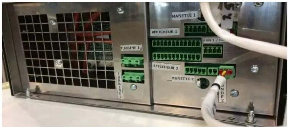
text_image
MANETTE 1 AFFICHEUR 1 FAN 1 / Fan TURBINE 1 TURBINE 2 AFFICHEUR 2 MANETTE 2 JN DEZProduct integration
Inductor to deported connexions
Capacitive touches version
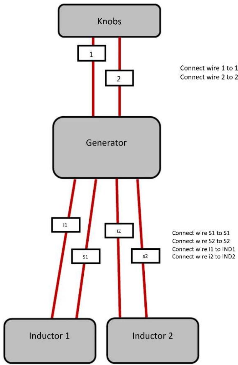
flowchart
graph TD
    A["Knobs"] -->|1| B["Generator"]
    A -->|2| B
    B -->|i1| C["Inductor 1"]
    B -->|i2| D["Inductor 2"]
    B -->|s1| C
    B -->|s2| D
    style A fill:#ccc,stroke:#333
    style B fill:#ccc,stroke:#333
    style C fill:#ccc,stroke:#333
    style D fill:#ccc,stroke:#333
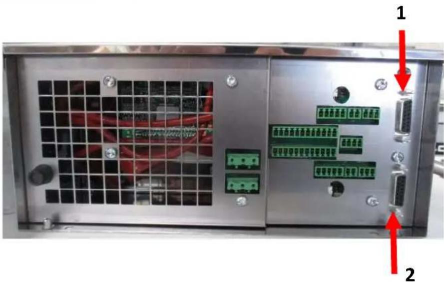
text_image
Internal view of a server rack with labeled ports and connectors, showing red arrows pointing to ports 1 and 2.Product integration
Power supply connections
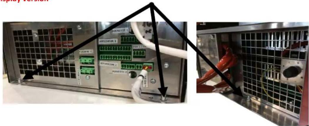
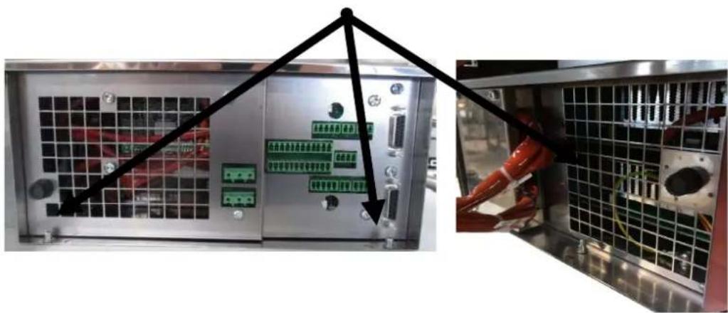
Unscrew the 3 screws :
Knob and display version
text_image
Photo of industrial equipment with labeled switches and a close-up view showing internal components, annotated with black arrows pointing to control panels.Capacitive touches version
natural_image
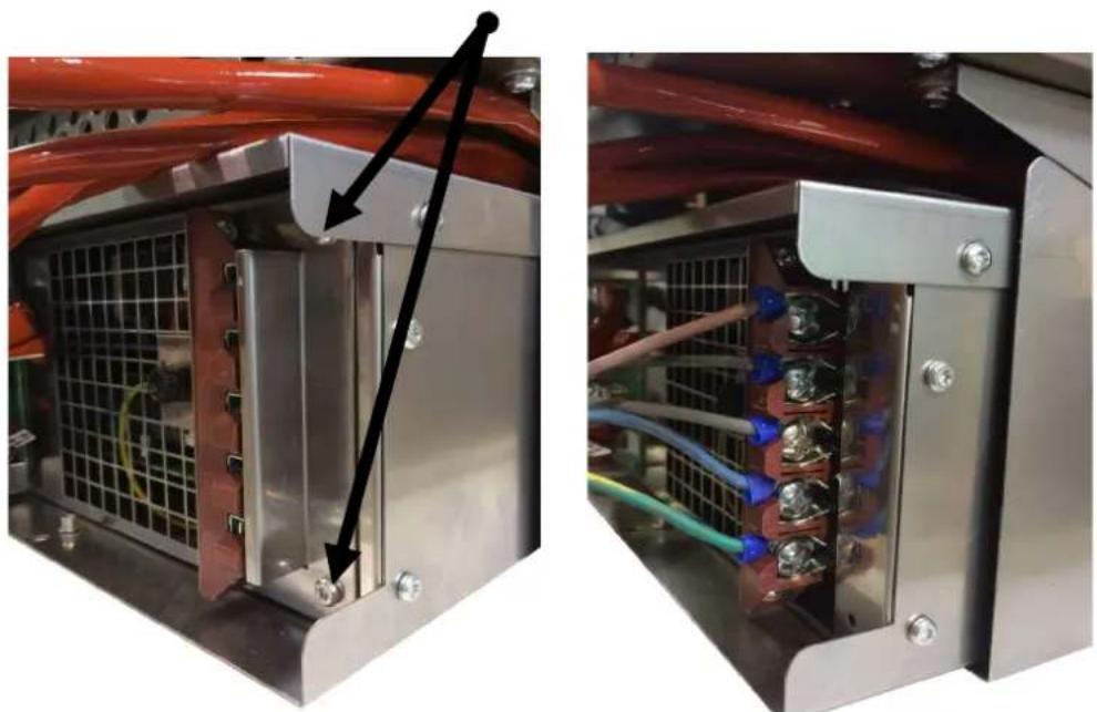
Interior view of a server rack with connected modules and wiring, showing a close-up of internal components (no visible text or symbols)Realease the generator from his casing and unscrew the 2 screws :
natural_image
Two views of an industrial electrical enclosure with visible wiring and components, no text or symbols present.Using your hob safety
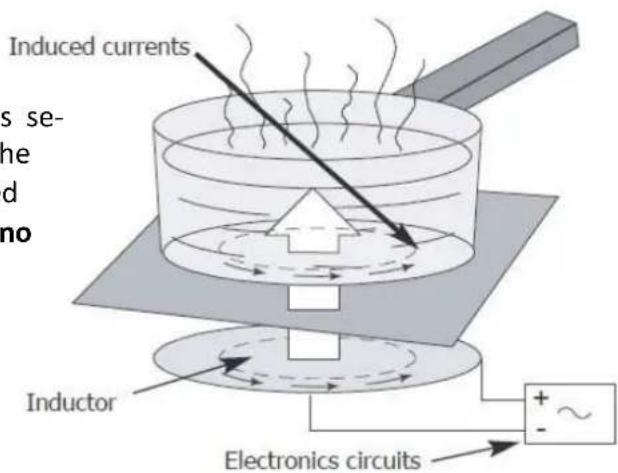
The induction principle
After the appliance is switched on and a power level is selected, electronic circuits produce induced currents in the base of the pan which instantly transmits the heat produced to the foodstuffs. Cooking takes place with practically no energy loss with a very high energy output.
If you have a heart pacemaker
Or other active implant fitted :
text_image
Induced currents Inductor Electronics circuitsThe functioning of the hob complies with the currently applicable norms concerning electromagnetic disturbance. Your induction cooking hob therefore fully meets the legal requirements (89/336/CEE directives). It has been designed not to cause disturbance to other electric appliances insofar as they also meet the requirements of the same regulations. Your induction hob emits magnetic fields in its immediate surroundings.
To avoid the possibility of interference between your cooking hob and a heart pacemaker, the latter must be designed to comply with the regulations that apply to it.
In this respect, we can therefore only guarantee the compliance of our own appliance. With regard to the compliance of a heart pacemaker or any eventual incompatibility, we recommend that you consult its manufacturer or your doctor.

If a crack appears in the surface of the glass, disconnect the appliance immediately from the mains supply to avoid the risk of electric shock. To do this, remove the fuses or operate the cut-off switch.
Do not use your appliance again until the vitroceramic glass has been replaced.
Only appropriate cookware should be placed on the hob. Do not put any other object on it, no matter what it is.
Ensure that the mains cable of any electric appliance that is plugged into a socket located in the immediate vicinity of the hob does not come into contact with the cooking zones.
When cooking, never use aluminium foil and never place products that are wrapped in aluminium or frozen products in aluminium trays, on the hob. The aluminium will melt and will permanently damage your appliance.
Do not clean your hob with huge amounts of water. Use a little bit of household alcohol.
Do not use a steam cleaner.
If the mains cable is damaged, it must be replaced by the manufacturer, their After Sales Service or a person with similar qualifications to avoid risk.
This appliance is not intended for use by anyone (including children) whose physical, sensory or mental capacities are reduced, or lacking experience or knowledge, unless they have been able to benefit from prior instructions as to the use of the appliance or supervision by a person who is responsible for their safety.
Supervise children to ensure that they do not play with the appliance.
Users should exercise caution if wearing items such as rings, watches or similar objects when using the appliance since these may heat up when positioned very close to the cooking surface.
Only use pans of the type and size recommended.
Cookware Recommended
Your induction hob is able to recognize the majority of pans and recipients.
Testing a pan: place the pan on the cooking zone with a power level set : if indicator stays on, your pan is compatible, if it flashes, your pan has not been recognised and cannot be used.
You can also test with the aid of a magnet: if it "sticks" to the base of the pan, then the pan is compatible with induction technology.
Induction-compatible pans are:
- enamelled steel pans with or without a nons-tick coating.
- stainless-steel pans designed for induction.
Most stainless steel pans are suitable if they pass the pan test. - cast-iron pans with or without an enamelled base.
- aluminium pans with special bases.
- NOTE
Pans made from glass, ceramic material, clay, aluminium (without special pan base), and copper, as well as certain non-magnetic stainless steels are not compatible with induction cooking. The indicator for the power level selected will flash to inform you of this.

Containers made of plastic must not be placed on hot surfaces
How to maintain and care for your hob
Avoid shocks when handling the pans.
The glass surface is very strong, however it is not unbreakable.
Avoid rubbing the pans over the surface of the appliance.
Centre your pan on the induction cooking zone.
Do not leave an empty pan on the induction zone.
Do not pre-heat foodstuffs on the highest power setting if you are using a pan with an anti-stick coating (of the teflon type) without or with a tiny a mount of cooking fat or oil.
Do not heat an unopened tin can, as it might burst.
All these defects that do not cause a non operation or inability to use are not covered by the guarantee.

Do not leave metal cooking utensils, lids, knives or any other metal objects on the induction cooking zone. These objects are liable to heat up if they remain too close to the magnetic field generated by the induction cooking zone.
If you think that your hob is not functioning correctly ..... this does not necessarily mean that a fault has occurred. Please verify the following in all cases :
| YOU NOTICE THAT ... | POSSIBLE CAUSES | WHAT YOU CAN DO |
| When putting into service, a bright display appears | Regular functioning | NOTHING: everything is normal |
| When putting into service, your installation short-circuits | The connection of you device is defective | Verify your connection or the conformity of the connection |
| The ventilation continues a few minutes after stopping the device | Cooling of the device | It's normal |
| The device doesn't work. The display on the casing stays off | The device is not supplied. The supply or the connection is defective | Inspect fuses and the circuit breaker of your electric installation |
| « F- » appears on the display | There is a touch activated permanently on the control keyboard | If the default doesn't disappear, call the after-sales service |
| « F7 » appears on the display | Electric circuits are over heating | Inspect the ventilation of the device and check if it is operational |
| The device doesn't work, another code appears on the display | Electric circuits doesn't work well | Call the after-sales service |
| After switching on the device and starting the cooking zone, the selected indicator continues to flash | The pan you are using is not compatible with the induction technology or is of a diameter smaller than 12 cm | See « Cookware Recommended section » |
| Pan makes noise while cooking | It's a vibration generated byy the circulation of the current in the pan | This phenomenon is normal with some type of pans. There is no danger |
| The device releases a smell during the first cookings | New device | Run the cooking during half an hour with a pan full of water |
If the vitroceramic hob suffers a breakage, split or crack, no matter how small, disconnect the appliance immediately and contact After-Sales Service.
Garantee
Keep the proof of purchase to use the guarantee service of your product.
Any modification such as drilling, welding, criimping, clinching, etc., is not permitted and is not covered by the manufacturer's warranty.
Any wrong modification or installation, which does not respect ADVENTYS' standards, is not covered by the manufacturer's warranty and will be permanently suspended.
The guarantee is subject to the non-modification of the product and its mechanical and electrical specifications. Opening the product cancels any form of warranty.
Any defects in appearance caused by the use of abrasive products or friction of cookware on the ceramic glass hob that does not result in a non-functioning or inability to use the appliance is not covered in the guarantee. The vitroceramic glass and the casing are not subject to warranty.
ANY REPAIRS MUST BE CARRIED OUT BY A QUALIFIED TECHNICIAN APPROVED BY ADVENTYS.
Only the distributors of our brand:
- KNOW YOUR APPLIANCE PERFECTLY AND HOW IT WORKS.
- FULLY APPLY OUR METHODS OF ADJUSTEMENT, MAINTENANCE AND REPAIRS.
- USE ONLY ORIGINAL SPARE PARTS.
In case of a claim or if you wish to order spare parts from your distributor, please specify the full reference numbers of your appliance (appliance type and serial number). This information appears on the plate fixed under the metal casing of the appliance.
The descriptions and characteristics given in this booklet are for information purposes only and do not imply commitment from the manufacturer. Concerned about the quality of our products, we reserve the right to carry out necessary changes or improvements without prior notice.
Original spare parts: ask your retailer for certified original spare parts during a maintenance operation.

text_image
ADVENTYSMade In France