STV-IR-3970-3 - Flat screen mount Irradio - Free user manual and instructions
Find the device manual for free STV-IR-3970-3 Irradio in PDF.


User questions about STV-IR-3970-3 Irradio
0 question about this device. Answer the ones you know or ask your own.
Ask a new question about this device
Download the instructions for your Flat screen mount in PDF format for free! Find your manual STV-IR-3970-3 - Irradio and take your electronic device back in hand. On this page are published all the documents necessary for the use of your device. STV-IR-3970-3 by Irradio.
USER MANUAL STV-IR-3970-3 Irradio
natural_image
Mechanical assembly with black metal frame and mounting brackets, no visible text or symbolsArt. 149302134
Wall bracket with three joints for 39"-70" TV
natural_image
Line drawing of a mechanical device with a handle and circular components (no text or symbols)
natural_image
Line drawing of a mechanical device with a handle and circular components (no text or symbols)2- Braccio assemblato (1 pz)
natural_image
Technical line drawing of a mechanical frame assembly (no text or symbols)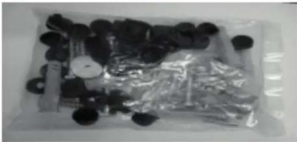
natural_image
Assorted black and metallic objects arranged in a tray, including plastic wrap and small items (no visible text or symbols)| Riga Componente Q.tà Riga Componente Q.tà | ||||||
| 4 |  Vite a testa esagonale M8x60mm Vite a testa esagonale M8x60mm | 4 | 12 | Vite M5x12mm | 4 | |
| 5 |  Tassello da muro M8x60mm Tassello da muro M8x60mm | 4 | 13 | Vite M5x30mm | 4 | |
| 6 |  Fermacavo Fermacavo | 2 | 14 | Vite M6x12mm | 4 | |
| 7 | 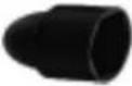 Copridado Copridado | 18 15 | Vite M6x30mm | 4 | ||
| 8 |  Rondella M8x22 Rondella M8x22 | 6 | 16 | Vite M8x16mm | 4 | |
| 9 |  Rondella M6x16 Rondella M6x16 | 4 | 17 | Vite M6x60mm | 4 | |
| 10 | 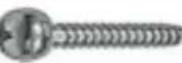 Vite M4x12mm Vite M4x12mm | 4 | 18 | Tassello da muro M6x60mm | ||
| 11 | 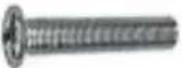 Vite M4x30mm Vite M4x30mm | 19 | Distanziale | 12 | ||
| 20 | Livella | 1 | ||||
text_image
Diagram showing a screw and screw assembly with three circular components, alongside a prohibition symbol.text_image
Technical diagram showing assembly or installation with screw fasteners, three circular components, and a labeled component box.natural_image
Diagram showing a mechanical assembly with screws, gauges, and a separate circular component (no text or symbols)natural_image
Technical line drawing of a dual-panel device with labeled components (no text or symbols)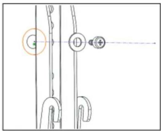
natural_image
Pure mechanical diagram showing a linkage mechanism with no text or symbols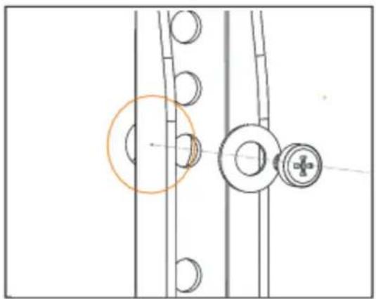
natural_image
Technical diagram showing mechanical components with no visible text or symbolsnatural_image
Technical line drawing of two mechanical components mounted on a rectangular frame, with no visible text or symbols.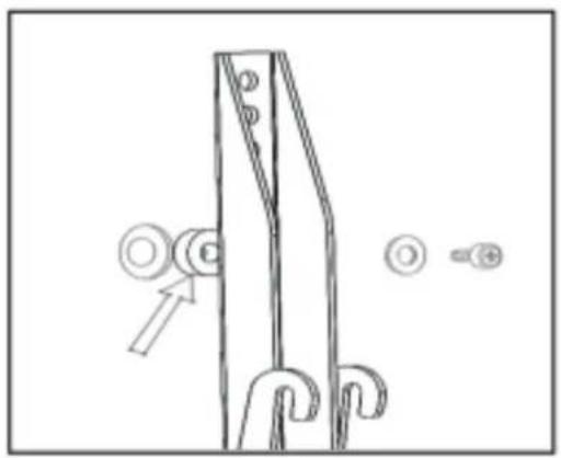
natural_image
Technical line drawing of a mechanical lifting or mounting bracket with no visible text or symbolsnatural_image
Pure technical diagram with no readable text, numbers, or symbols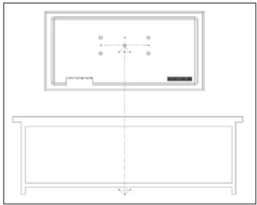
natural_image
Technical line drawing of a room layout with furniture and fixtures (no text or symbols)natural_image
Top-down schematic of a rectangular electronic component with four circular ports and central circular feature (no text or symbols)natural_image
Technical line drawing of a mechanical assembly with a circular component and mounting bracket (no text or symbols)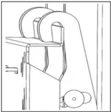
natural_image
Technical line drawing of a mechanical device with rollers and a handle (no text or symbols)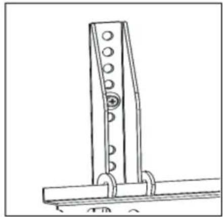
natural_image
Technical line drawing of a mechanical bracket or support structure (no text or symbols)natural_image
Technical line drawing of a mechanical device with mounting holes and structural supports (no text or symbols)natural_image
Technical line drawing of a mechanical component with two circular features and a hexagonal base (no text or symbols)Wall bracket for TV from 39" (99cm) to 70" (178cm)
ASSEMBLY GUIDE
Please, read the instructions carefully and keep them for future reference. Do not use this appliance for purposes other than those described.
Safety information and specifications
CAUTION: Do not use this product for any purpose not explicitly specified.
Using for other cases may cause properly damage or personal injury. On the other side if you cannot understand of instruction or doubts about safety of this, contact to your customer service or call a qualified contractor. Melchioni is not responsible for any damage or injury due to incorrect installation or use. The weight of your TV should not be more than 40 kg. The wall must be capable of supporting weight of your TV and wall mount together. Keep these times away from young children.
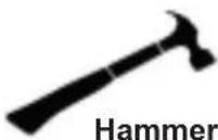
You will need the following tools to assemble your TV wall mount:

text_image
Drill Measuring tape and pencil 8/32" (8mm) drill bit Socket wrench (13mm)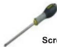
Package contents
Make sure that you have all the hardware necessary to assemble your TV wall mount:
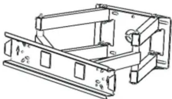
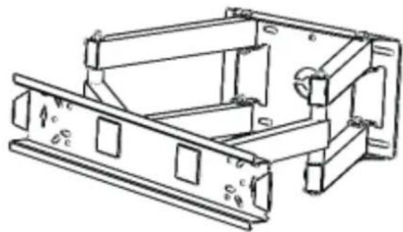
1- Vertical assembled Brackets (Q.ty 2)

natural_image
Line drawing of a mechanical device with a curved handle and mounting bracket (no text or symbols)
natural_image
Line drawing of a mechanical device with a curved handle and circular components (no text or symbols)2- Base assembled arm (Q.ty 1)
3- Hardware including Nuts, Bolts and accessories in plastic package (Q.ty 1)
natural_image
Technical line drawing of a mechanical assembly with mounting brackets and mounting holes (no text or symbols)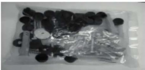
natural_image
Assorted black circular objects and plastic bags arranged in a tray (no visible text or symbols)| Row Hardware Q.tà Row Hardware Q.tà | |||||
| 4 |  M8* 60mm Head coach screw M8* 60mm Head coach screw | 4 | 12 | M5* 12mm Screw | |
| 5 |  M8* 60mm Concrete anchor M8* 60mm Concrete anchor | 4 | 13 | M5* 30mm Screw | |
| 6 |  Cable keeper Cable keeper | 2 | 14 | M6* 12mm Screw | |
| 7 |  Nut cap Nut cap | 18 15 | M6* 30mm Screw | ||
| 8 |  M8* 22 Washer M8* 22 Washer | 6 | 16 | M8* 16mm Screw | |
| 9 |  M6* 16 Washer M6* 16 Washer | 4 | 17 | M6* 60mm Screw | |
| 10 |  M4* 12mm Screw M4* 12mm Screw | 4 | 18 | M6* 60mm Concrete anchor | |
| 11 |  M4* 30mm Screw M4* 30mm Screw | 19 | Spacer | ||
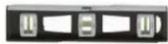
| 20 | Level | ||||
Installation instructions
Step1 – Determine that your TV has a flat back or an irregular form of TV or obstructed back
- Carefully place your TV screen face-down on a soft place, clean that surface to protect the screen from any damages and scratches.
- If your TV has a table-top stand attached, remove the stand. See the documentation that came with your TV for instruction.
- Temporarily lay the brackets on the back of your TV.
- Align screws, brackets and TV with the mounting screw holes.
- Identify that which type of back your TV may have:
- Flat back: the brackets lay flush the back of your TV and do not block any jacks and you do not need spacers when assembling the wall mount or any other distances.

text_image
Diagram showing a screw and screw assembly with three circular components, alongside a prohibition symbol.- Obstructed back: The brackets block any of the jacks on the back of your TV and properly you will need spacers when assembling the wall mount.

text_image
Technical diagram showing a mechanical assembly with screws, rollers, and a base plate, alongside a magnified view of a cylindrical component.- Irregularly shape back: In this type, there is gape between the brackets and surface of wall mount. You will need spacers when assembling the wall mount.

natural_image
Diagram showing a mechanical assembly with screws and a circular component, no text or symbols present- Remove the vertical brackets.
Step 2- Select screws, washers, and spacers
-
Select the hardware for your TV (screws, washers, and spacers). A limited number of TVs come with number of hardware included. (If there are screws that came with the TV, there are almost always in the holes on the back of the TV). If you don't know the correct length of the mounting screws your TV requires, test various sizes by hand threading the screws.
-
Select one of the following types of screws:
M4* 12 mm Screw (10)
M4* 30 MM Screw (11)
M5* 12 mm Screw (12)
M5* 30 mm Screw (13)
M6* 12 mm Screw (14)
M6* 30 mm Screw (15)
M8* 16 mm Screw (16)
Use washers for all screws.
For an irregular or obstructed TV back, you can use some spacers.
Caution: use the correct length of screws for installation. If you doubt about installation by yourself, stop immediately and contact to customer service. Using hardware that is too long may damage your TV and on the other hand using too short may cause your Tv fall from the mount and do damage or injuries.
- Remove the screws for fitting other steps.
- For flat back TV, directly attaching the vertical brackets to TVs with irregular or obstructed backs.
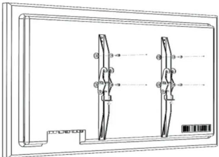
Step 3- Option 1: attaching the vertical brackets to TVs with a flat back
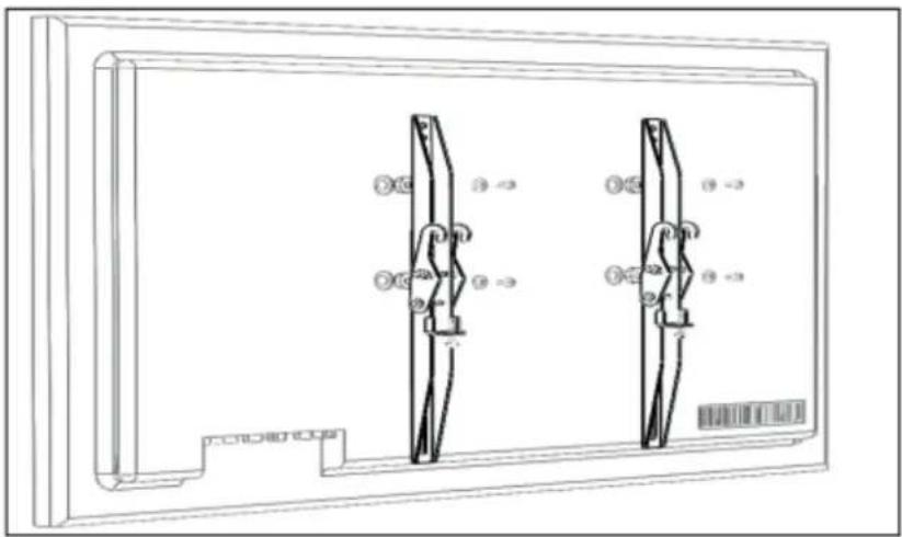
- Align TVs holes on the bracket holes with screws on the back of TV. The brackets must be level.
- Place washers M6 16 mm (6) concentric and align on the holes of brackets and then insert
the screws (10-14) through the washers.
- Tighten the screws until fasting brackets to TV. Notice that do not over tighten
natural_image
Technical line drawing of a mechanical component with two vertical supports and numbered parts (no text or symbols)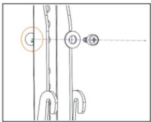
natural_image
Technical diagram showing mechanical components with no visible text or symbols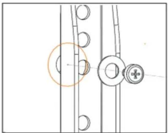
natural_image
Technical line drawing of mechanical components with no visible text or symbolsStep 3- Option 2: attaching the vertical brackets to TVs with irregular or obstructed backs
- Place the spacers over the screw holes between brackets and TVs back.
- Align the brackets over the spacers, after that place the washers over the holes in the brackets and insert the screws through the washers, brackets and spacers. Make sure that the brackets are level.
- Tighten the screws until snug against the vertical brackets. Do not over tighten.
natural_image
Technical line drawing of two mechanical components mounted on a rectangular frame (no text or symbols)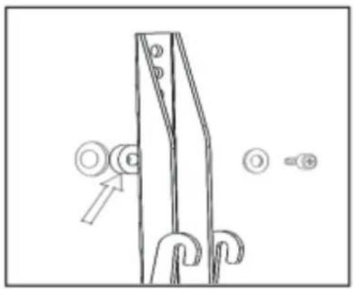
natural_image
Technical line drawing of a mechanical lifting or mounting bracket with no visible text or symbolsStep 4 – Determine wall-mount location
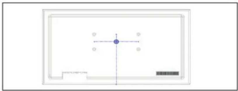
Place TV at the center of the wall plate at the arm, before drill holes.
- Measure the distance from the bottom of TV to the middle of four mounting screw holes. This is measurement.
- Choose the exact place on the wall that related to your design. In this part, measure the bottom of TVs place that you want from floor. But notice that Tv should place above any furniture such as (TV stand, decoration box, blue ray box and speaker box).
• Top of the Tv should be level. - At the end of this step use pencil to mark TV spot on the wall.
natural_image
Pure technical diagram with no readable text, numbers, or symbols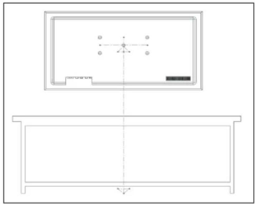
natural_image
Technical line drawing of a room layout with furniture and fixtures (no text or symbols)Step 5- Installing arm on a solid concrete or concrete clock wall
Caution: To prevent property damage or personal injury, never drill into the mortar between the blocks. Plate directly onto the concrete surface.
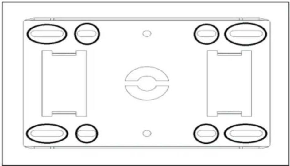
- Align the center of the wall plate at the arm at the height determined in the previous step and make sure that it is level as you know. Mark the 6 screw hole locations.
- Drill pilot holes to the depth of 60mm and 8mm diameter.
- Insert concrete wall anchors into the pilot holes and use a hammer to make sure that the anchors are flush with the concrete surface.
- Align the wall plate with the anchors and then insert the screws through the holes in the wall plate assembly. Tighten the screws until fasting the wall plate and anchors.
- Do not over tighten for avoiding potential injuries or property damage.
- Notice that the wall plate should stand level vertically and horizontally. The degree between the arm and the wall must be 90 degrees.
natural_image
Top-down schematic of a rectangular electronic device with four circular ports and central circular component (no text or symbols)Step 6 – Attach the TV to the arm
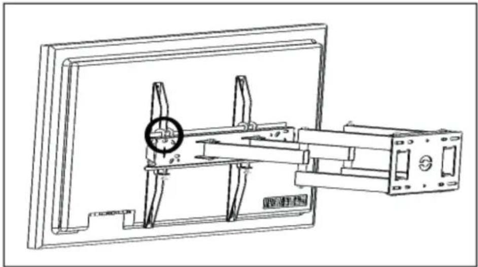
- To make it easier to attach the TV to the wall plate, pick the Tv up from the corners in a way you can see back of your TV.
- If your TV is huge, heavy or inaccessibility to say brackets and arm, you will need assistance into this step.
- At first, insert hooks that assembled to the brackets on top of the main body bent that assembled to the arm.
natural_image
Technical line drawing of a mechanical assembly with a magnified inset showing a circular detail (no text or symbols)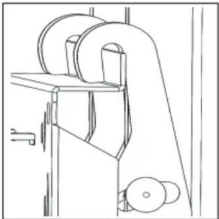
natural_image
Technical line drawing of a mechanical device with rollers and a handle (no text or symbols)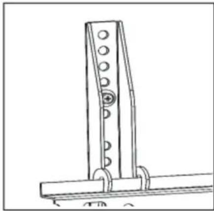
natural_image
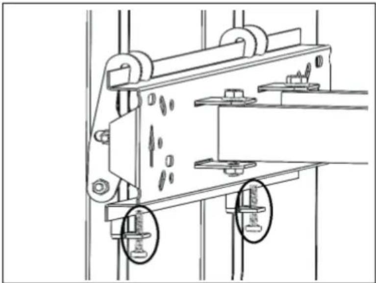
Technical line drawing of a mechanical bracket or support structure (no text or symbols)- Then, tight the screw that assembled on the brackets to the bottom bent part on the body.
natural_image
Technical line drawing of a mechanical device with mounting holes and structural components (no text or symbols)- Make sure that your TV stand resistantly on the body.
Step 7 – Making adjustment and managing cables
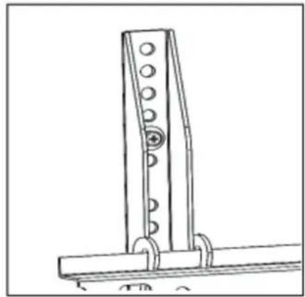
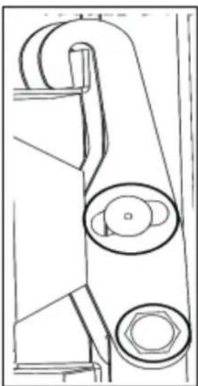
- You can change the Tv position vertically by two screws that assembled on the hooks.
natural_image
Technical line drawing of a mechanical component with two circular features (no text or symbols)- Note: When you sure that your TV is standing in place that you want, tighten the screws and nuts to prevent unwanted movement.
- Manage all cables by two cable keepers which are in your packet. Put cable keepers to two profiles and then pass cables from inside of cable keeper to prevent any slack, routing cables along the arms and providing a clean look to your installation.
Removing the TV from the wall mount.
To remove your TV from the wall plate assembly, disconnect all cables and then reserve the procedures in step 6.
Care and maintenance.
As a good practice of care and maintenance, carry out periodic checks on the tightening of the anchors and check the integrity of the product.
Warranty
Melchioni Spa, based in Milan (Italy), via Colletta 37, recognizes a conventional guarantee on the product for a period of two years from the date of the first purchase by the consumer. This guarantee does not affect the validity of the legislation in force concerning consumer goods (Legislative Decree 6 September 2005 n. 206 art. 128 and following), of which the consumer remains the owner. This guarantee applies to the entire territory of the European Union.
The components or parts that are found to be defective for ascertained manufacturing causes will be repaired or replaced free of charge through the dealer, during the above warranty period. Melchioni Spa reserves the right to make a complete replacement of the device, if repairability is impossible or excessively expensive, with another device of similar characteristics (Legislative Decree 6 September 2005 no. 206 art. 130) during the warranty period. In this case, the validity of the warranty remains that of the original purchase: the service provided under warranty does not extend the warranty period.
In any case, this appliance will not be considered defective in terms of materials or manufacture should it be adapted, changed or adjusted, in order to comply with national or local safety and / or technical standards, in force in a country other than that for which it is was originally designed and manufactured. This appliance has been designed and built for domestic use only: any other use will invalidate the benefits of the guarantee.
The warranty does not cover:
- parts subject to wear or tear, nor those parts that require periodic replacement and / or maintenance.
• professional use of the product - malfunctions or any defects due to incorrect installation, configuration, software / BIOS / firmware update not performed by authorized Melchioni Spa
• repairs or interventions carried out by persons not authorized by Melchioni Spa
• manipulation of assembly components or, where applicable, of the software - defects caused by fall or transport, lightning, voltage fluctuations, liquid infiltration, opening of the appliance, bad weather, fire, public disturbances, inadequate ventilation or incorrect power supply
• any accessories, for example: boxes, bags, batteries, etc. used with this product
• home interventions for convenience checks or presumed defects
The recognition of the guarantee by Melchioni Spa is subject to the presentation of a tax document that proves the actual date of purchase. The same must not show any tampering or deletions, in the presence of which Melchioni Spa reserves the right to refuse the provision of treatment under warranty.
The warranty will not be recognized if the serial number or model of the appliance is non-existent, abraded or modified.
This warranty does not include any right to compensation for direct or indirect damage, of any nature, to people or things, caused by any inefficiency of the appliance. Any extensions, promises or services in this regard, insured by the retailer, will be borne by the latter.
natural_image
Two technical line drawings of a mechanical component or bracket, showing internal components and mounting holes (no text or symbols)2- Brazo montado base (cant. 1)
natural_image
Technical line drawing of a mechanical frame assembly (no text or symbols)natural_image
Assorted black circular objects and plastic sheets arranged in a tray (no visible text or symbols)| Fila Herramientas/material Cant. Fila Herramientas/material Cant. | material Cant. | |||||
| 4 |  Tornillo tirafondo M8* 60 mm Tornillo tirafondo M8* 60 mm | 4 | 12 | Tornillo M5* 12 mm | 4 | |
| 5 |  Anclaje de hormigón M8* 60 mm Anclaje de hormigón M8* 60 mm | 4 | 13 | Tornillo M5* 30mm | 4 | |
| 6 |  Guardacables Guardacables | 2 | 14 | Tornillo M6* 12mm | 4 | |
| 7 |  Tuerca tapón Tuerca tapón | 18 15 | Tornillo M6* 30 mm | 4 | ||
| 8 |  Arandela M8* 22 Arandela M8* 22 | 6 | 16 | Tornillo M8* 16mm | 4 | |
| 9 |  Arandela M6* 16 Arandela M6* 16 | 4 | 17 | Tornillo M6* 60 mm | 4 | |
| 10 |  Tornillo M4* 12 mm Tornillo M4* 12 mm | 4 | 18 | Anclaje de hormigón M6* 60 mm | ||
| 11 |  Tornillo M4* 30 mm Tornillo M4* 30 mm | 19 | Espaciador | 12 | ||
| 20 | Nivel | 1 | ||||
text_image
Diagram showing a screw and nut assembly with three circular components, alongside a prohibition symbol.text_image
Diagram showing mechanical assembly with screws, rollers, and a base plate, alongside a magnified view of a cylindrical component.natural_image
Diagram showing a mechanical assembly with screws and a cylindrical component, alongside a magnified view of a cylindrical part (no text or symbols)natural_image
Technical line drawing of a dual-panel device with labeled components (no text or symbols)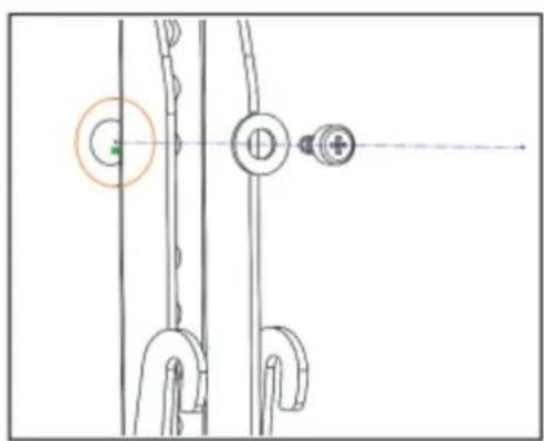
natural_image
Pure mechanical diagram showing linkage components without any text, numbers, or symbols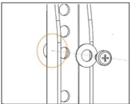
natural_image
Technical diagram showing mechanical components with no visible text or symbolsnatural_image
Technical line drawing of two mechanical components mounted on a rectangular frame, with no visible text or symbols.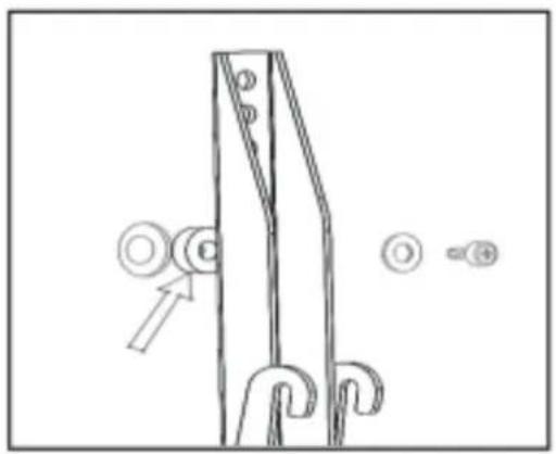
natural_image
Technical line drawing of a mechanical lifting or mounting bracket with no visible text or symbolsnatural_image
Pure technical diagram with geometric shapes and no readable text or symbols
natural_image
Technical line drawing of a room layout with furniture and fixtures (no text or symbols)natural_image
Top-down schematic of a rectangular electronic device with four circular ports and a central circular component (no text or symbols)Paso 6 – Conecte el televisor al brazo
natural_image
Technical line drawing of a mechanical assembly with no visible text or symbols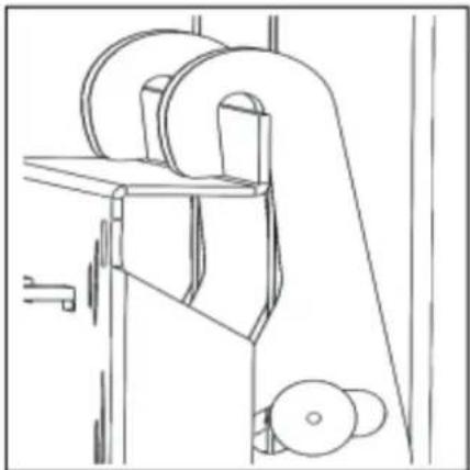
natural_image
Technical line drawing of a mechanical device with rollers and levers (no text or symbols)
natural_image
Technical line drawing of a mechanical bracket or support structure with no visible text or symbolsnatural_image
Technical line drawing of a mechanical device with mounting holes and structural components (no text or symbols)natural_image
Technical line drawing of a mechanical component with two circular features (no text or symbols)natural_image
Line drawing of a mechanical device with a handle and circular components (no text or symbols)natural_image
Line drawing of a mechanical device with a handle and circular components (no text or symbols)natural_image
Technical line drawing of a mechanical assembly with mounting brackets and structural ribs (no text or symbols)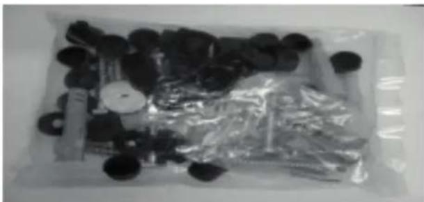
natural_image
Assorted black circular objects and plastic wrap arranged in a tray (no visible text or symbols)text_image
Diagram showing a screwdriver and two screwdrivers above a tray, with a prohibition symbol below.text_image
Technical diagram showing assembly or installation with screw, housing, and component labels, alongside a magnified view of a cylindrical object.natural_image
Diagram showing a mechanical assembly with screws, a plate, and a magnified view of a cylindrical component (no text or symbols)natural_image
Technical line drawing of a dual-panel device with labeled components (no text or symbols)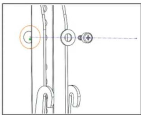
natural_image
Pure mechanical diagram showing linkage components without any text, numbers, or symbols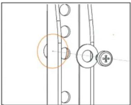
natural_image
Technical diagram showing mechanical components with no visible text or symbolsnatural_image
Technical line drawing of two mechanical components mounted on a rectangular frame, with no visible text or symbols.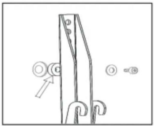
natural_image
Technical line drawing of a mechanical lifting or mounting bracket with no visible text or symbolsnatural_image
Pure technical diagram with no readable text, numbers, or symbols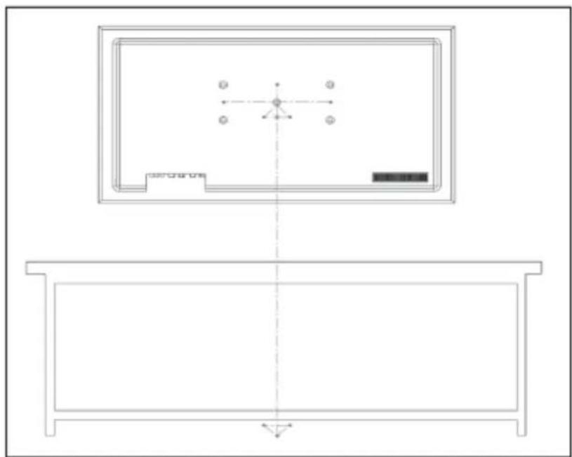
natural_image
Technical line drawing of a room layout with furniture and a central display (no text or symbols)natural_image
Top-down schematic of a rectangular device with four circular components and central circular feature (no text or symbols)natural_image
Technical line drawing of a mechanical assembly with a central dial indicator (no text or symbols)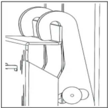
natural_image
Technical line drawing of a mechanical device with rollers and levers (no text or symbols)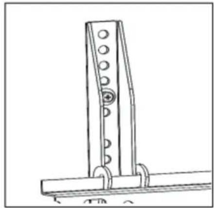
natural_image
Technical line drawing of a mechanical bracket or support structure with no visible text or symbolsnatural_image
Technical line drawing of a mechanical device with mounting brackets and structural supports (no text or symbols)natural_image
Technical line drawing of a mechanical component with two circular features and a hexagonal base (no text or symbols)natural_image
Line drawing of a mechanical component with a curved handle and mounting bracket (no text or symbols)natural_image
Line drawing of a mechanical device with a handle and circular components (no text or symbols)natural_image
Technical line drawing of a mechanical assembly with mounting brackets and structural ribs (no text or symbols)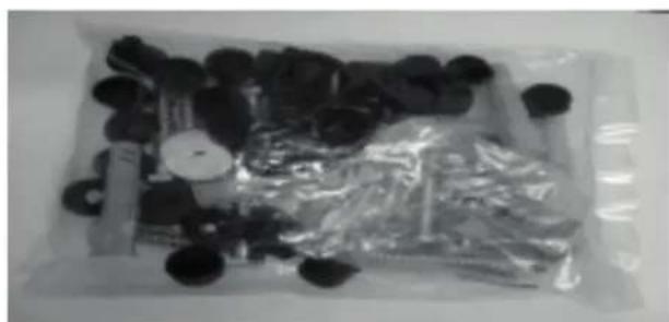
natural_image
Assorted black circular objects and plastic sheets arranged in a tray (no visible text or symbols)text_image
Diagram showing screw installation with two screws and a battery plate, alongside a prohibition symbol.text_image
Diagram showing a mechanical assembly with screws, rollers, and a base plate, alongside a magnified view of a cylindrical component.natural_image
Diagram showing a mechanical assembly with screws, a plate, and a magnified view of a cylindrical component (no text or symbols)natural_image
Technical line drawing of a mechanical component with two vertical supports and numbered features (no text or symbols)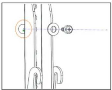
natural_image
Pure mechanical diagram showing linkage components without any text, numbers, or symbols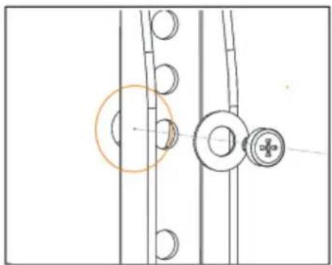
natural_image
Technical diagram showing mechanical components with no visible text or symbolsnatural_image
Technical line drawing of two mechanical components mounted on a panel, with no visible text or symbols.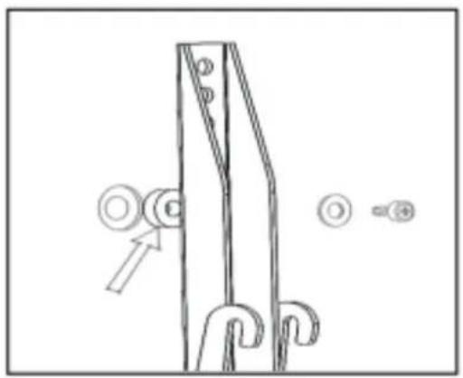
natural_image
Technical line drawing of a mechanical component with no visible text or symbolsnatural_image
Pure architectural floor plan lines without any text, numbers, or symbols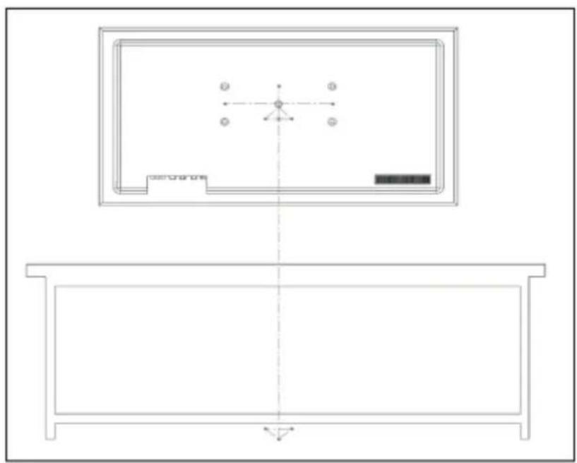
natural_image
Technical line drawing of a room layout with furniture and fixtures (no text or symbols)natural_image
Top-down schematic of a rectangular electronic device with four circular ports and central circular component (no text or symbols)natural_image
Technical line drawing of a mechanical assembly with a central component and mounting bracket (no text or symbols)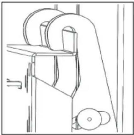
natural_image
Technical line drawing of a mechanical device with rollers and levers (no text or symbols)