B-7133 - Garden hose T&S - Free user manual and instructions
Find the device manual for free B-7133 T&S in PDF.


| Product Type | Garden Hose Reel |
| Brand | T&S |
| Model | B-7133 |
| Category | Garden Hose |
| Main Material | Stainless Steel and Plastic |
| Hose Capacity | Variable Length (depending on model) |
| Locking System | Ratchet with 4 clicks per half-turn |
| Tension Adjustment | Pre-tensioned at factory, manually adjustable |
| Mounting Type | Wall-mounted, base down or up |
| Secondary Support Required | Yes, safety chain or cable |
| Regular Maintenance | Check hose wear, lubricate O-rings |
| Prohibited Chemicals | Yes, do not use in hose or reel |
| Tools Required for Installation | Wrenches 10, 13, 16, 19 mm; Phillips screwdriver; pliers |
| Swivel Fitting | Replaceable if leak (O-ring) |
| Main Spring | Replaceable, supplied in sealed container |
| Manual Available | 40 pages, PDF format |
| Warranty | Not specified in the manual |
Frequently Asked Questions - B-7133 T&S
User questions about B-7133 T&S
0 question about this device. Answer the ones you know or ask your own.
Ask a new question about this device
Download the instructions for your Garden hose in PDF format for free! Find your manual B-7133 - T&S and take your electronic device back in hand. On this page are published all the documents necessary for the use of your device. B-7133 by T&S.
USER MANUAL B-7133 T&S
Limited Two Year Warranty
T&S warrants to the original purchaser (other than for purposes of resale) that such product is free from defects in material and workmanship for a period of two (2) years from the date of purchase, except hose. Hose supplied by T&S carries a one (1) year warranty only. During these warranty periods, if the product is found to be defective, T&S shall, at its options, repair and/or replace it. To obtain warranty service, products must be returned to...
T&S Brass and Bronze Works, Inc.
Attn: Warranty Repair Department
2 Saddleback Cove
Travelers Rest, SC 29690
Shipping, freight, insurance, and other transportation charges of the product to T&S and the return of repaired or replaced product to the purchaser are the responsibility of the purchaser. Repair and/or replacement shall be made within a reasonable time after receipt by T&S of the returned product. This warranty does not cover items which have received secondary finishing or have been altered or modified after purchase, or for defects caused by abuse to or misuse of the product; including the use of chemicals through the hose &/or the reel, normal wear and tear or shipment of the products.
Any express warranty not provided herein, and any remedy for Breach of Contract which might arise, is hereby excluded and disclaimed. Any implied warranties of merchantability or fitness for a particular purpose are limited in duration to the warranty period provided on the product. Under no circumstances shall T&S be liable for loss of use or any special consequential costs, expenses or damages.
Some states do not allow limitations on how long and implied warranty lasts or the exclusion or limitation of incidental or consequential damages, so the above limitations or exclusions may not apply to you. Specific rights under this warranty and other rights vary from state to state.
Attention California Residents:
WARNING: This product contains chemicals known to the State of California to cause cancer, and birth defects or other reproductive harm.
P/N:098-014921-45 Rev.8
Date: 12-18-15
Drawn: TEH
Checked: JRM 06-02-16
Approved: JHB 06-02-16
Installation and Maintenance Instructions
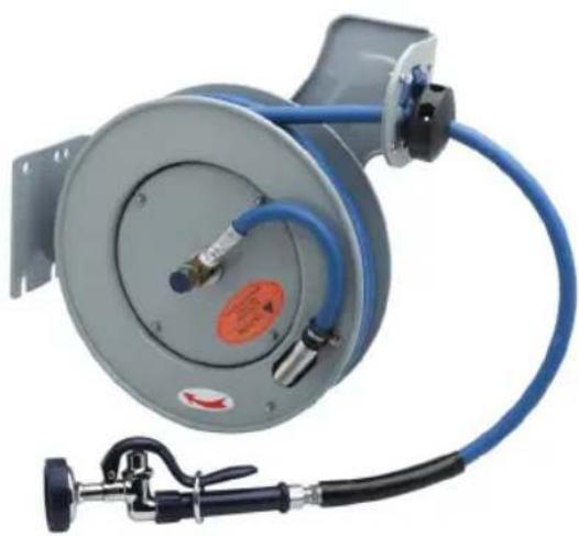
B-7000 SERIES EU-7100 SERIES EPOXY POWDER COATED & STAINLESS STEEL REELS
U.S. Patent #D551,945
Espanol:
S/S = Stainless Steel ES = Enclosed Small EL = Enclosed Large
Part Number Guide
HOSE KITS - 6
PART NUMBER HOSE I.D. HOSE LENGTH MAX. PRESSURE
017938-45 3/8" 12' 300 psi
014944-45 3/8" 15' 300 psi
014943-45 3/8" 30' 300 psi
014941-45 3/8" 35' 300 psi
014942-45 3/8" 50' 300 psi
015089-45 1/2" 35' 300 psi
014945-45 1/2" 50' 300 psi
O-RING KIT - 7
PART NUMBER HOSE I.D. HOSE LENGTH MAX. PRESSURE
014948-45 3/8" 12^ / 15^ / 30^ / 35^ 300 psi
019473-45 3 / 8^ ;1 / 2^ 35^(1 / 2^ Only)/50' 300 psi
S/S = Stainless Steel ES = Enclosed Small EL = Enclosed Large
General Instructions
Important Safety Instructions
DANGER: Immediate hazards which will result in severe personal injury or death.
WARNING: Hazards or unsafe practices which could result in severe personal injury or death.
CAUTION: Hazards or unsafe practices which may result in minor personal injury or product or property damage.
WARNING: Failure to read, understand or follow these instructions could lead to hazards or unsafe practices which could result in severe personal injury or death.
CAUTION: Do not utilize chemicals in the hose &/or the reel. Chemicals can cause premature failure of the hose &/or the seals.
CAUTION: Operators need to be instructed on the safe, proper use and maintenance of this product. Keep this manual for future reference. Hazards or unsafe practices may result in minor personal injury or product or property damage.
TOOLS: (a) wrench: 10mm, 13mm, 16mm & 19mm; (b) nut driver: 8mm and 10mm; (c) needle-nose pliers (d) cross-recess screw driver #2, and (e) external retaining ring pliers. B-7102 models include a fl at wrench.
Installation
MOUNTING
Reels complete with hose come set at proper tension and are ready to install. (Fig. 1) Fixed base of reel allows mounting in several different positions including wall mount, base down, or base up. If moving guide arm, three nuts (17mm SS or 19mm painted) on side of reel must be removed. If reel is enclosed version, remove and mount base to surface, then attach reel to base.
MOUNTING B-7102
The B-7102 mounting flange is part of the support frame. This hose reel can be positioned as wall mounted (as shipped) or base up. To convert from one position to another:
- Temporarily clamp unit to a work surface. Remove all tension from reel; see "Tension Adjustment."
- Slide fl at wrench provided between spool assembly and support frame onto shaft to hold it from turning during the next step.
- Loosen but do not remove the shaft nut (22mm hex) until the shaft is free to turn in the support frame hole.
- Remove the (2) screws securing the hose guide bracket, move the bracket to the desired location and reinstall the screws.
- Turn the spool and shaft relative to the support frame until the hose fitting at the formed metal tube assembly is parallel with the hose guide bushing centerline.
- Retighten the shaft nut. Re-tension reel (see "Tension Adjustment")
General Instructions
Installation
General Mounting Requirements
(Fig. 2) Main-shaft must be horizontal.
- (Fig. 3a) Swivel inlet must be connected with fl exible hose. Rigid pipe may cause premature wear and affect performance.
- (Fig. 3b) Centerline of spool assembly must be in-line with hose pull out. To adjust guide arm, remove screws holding it to base and rotate to desired group of mounting holes.
- Qualified personnel must evaluate wall or ceiling fastening. Mounting through the (4) 1/2'' dia. holes on the base may vary due to surface materials. A possible method for concrete, brick and cement block is a sleeve anchor type stud fastener (fi g. 4) instead of, sometimes difficult to install, long lag bolts.
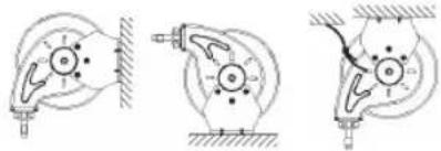
Fig.1
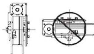
Fig. 2
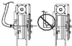
Fig. 3a
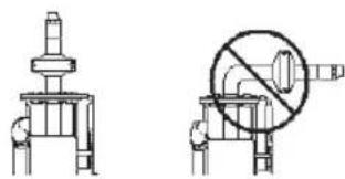
Fig. 3b
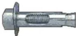
Fig. 4
General Instructions
SECONDARY SUPPORT
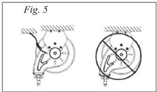
WARNING: A secondary support chain is required for all objects mounted over head to protect personnel in case of failure in mounting hardware or structure.
- (Fig. 5) Attach support cable/chain to one of the slots in guide arm. Other end of support cable to be attached to a support other than the main one supporting the hose reel.
- The safety chain/cable should allow reel to drop no more than 6 to 12 in. if primary connection is released.
Adjustment
RATCHET LOCK
CAUTION: To avoid damage to the reel or personnel, always hold on to hose while it is rewinding. Hazards or unsafe practices which may result in minor personal injury or product or property damage.
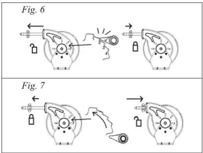
- Ratchet "clicks" four times every half-spool revolution.
Note: For B-7102 ratchet clicks five times every full revolution. - (Fig. 6) To latch reel, slowly pull out hose and allow it to retract after clicks 1-4.
- (Fig. 7) To unlatch, slowly pull out hose until "clicking" stops, then let hose rewind until hose stop rests against guide.
- To disable ratchet, see section in servicing on "Ratchet Lock Replacement/Removal".
General Instructions
TENSION ADJUSTMENT
CAUTION: Always leave at least 1-2 turns between full extension and when the spring is wound tight. If entire hose cannot be pulled out, decrease tension until full extension is possible. Failure to test for adequate spring revolutions can cause damage to reel. Hazards or unsafe practices may result in minor personal injury or product or property damage.
- Reels shipped with hose are pre-tensioned at factory. Reels shipped without hose are pretensioned after installing hose, but before making final hose or inlet connections.
- (Fig. 8) To pre-tension hose reel, pull hose out to allow one
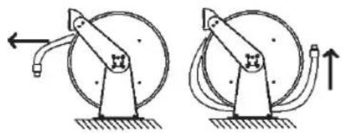
Fig. 8
full wrap of hose to be looped back over drum assembly. Hold drum from turning by engaging ratchet (fi g.6), and loop hose back on drum. Repeat until desired tension is achieved. After tension is set, pull out hose. If full hose extension is not possible, remove pre-tension turns as needed by reversing process.
Service
CAUTION: Remove all tension before servicing. Hazards or unsafe practices may result in minor personal injury, product or property damage.
CAUTION: Do not utilize chemicals in the hose &/or the reel. Chemicals can cause premature failure of the hose &/or the seals.
WARNING: Before performing any service, always disconnect and lock out compressed air or fluid, and remove all spring tension. Hazards or unsafe practices could result in severe personal injury or death.
ENCLOSED HOSE REELS
- Enclosed hose reels require additional steps to remove outer and middle covers (fi g 9.1) before performing service. Cover is removed by loosening (2) 10mm nuts. Reinstall with middle cover edge as shown (fi g 9.2).
HOSE INSTALLATION AND REPLACEMENT
- Remove all tension from reel (see Tension Adjustment). Remove hose-stop, unwind hose from reel, remove strain-relief (8mm nut) and unscrew hose from its connection point (depending on model, swivel tee or metal tube assembly). Feed new hose through roller guide and through slot in flange
(except on B-7102). Reattach hose to its connection (use thread sealant or Tefl on tape for male threaded hose fittings; the metal tube assembly on B-7102 does not require thread sealant). Reattach strain relief clamp, wind onto drum assembly and re-tension reel.
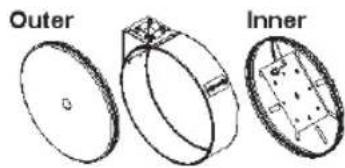
Fig. 9.1
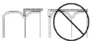
Fig. 9.2
General Instructions
RATCHET LOCK REPLACEMENT/REMOVAL
To replace or remove ratchet:
- Turn off or lockout air/fluid supply to reel
- Remove all tension, see "Tension Adjustment"
(Fig. 10.1) Remove spool from stand (24mm or 22mm nut)
(Fig. 10.2) Replace or remove ratchet lock and spring (small external retaining ring pliers or for B-7102, 10mm hex retaining nuts) - Replace spool and tighten shaft nut (24mm or 22mm)
- Retension, see "Tension Adjustment"
Ratchet plate is secured with 10mm nuts. The B-7102 ratchet plate is not replaceable.
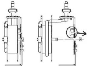
Fig. 10.1
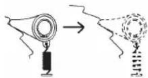
Fig. 10.2
MAIN-SPRING ASSEMBLY REPLACEMENT
WARNING: Never remove spring from its sealed container. Replacement springs are in a sealed assembly for safety. There is no need to remove them. Serious injury or death could result from removal of spring from its container.
NOTE: If spring is to be replaced when not broken make sure to remove all tension before proceeding.
If reel has no retraction tension, then main-spring likely needs replacement.
To replace main-spring (all models except B-7102):
- Turn off or lockout air/fluid supply to reel
- Remove supply hose to swivel
- Remove swivel by loosening its hex end (round body is 24mm or square body is 27mm )
- Remove retaining ring (medium external retaining ring pliers) and spacer washers from main-shaft
Pull spring pocket assembly, with spool, off drum axle (if plastic spool, axle is part of spool assembly) - (Fig. 11) Remove nuts (10mm) holding spring pocket to spool, install new containerized spring
- Reverse procedure to reassemble (use Teflon tape or sealant on hose connections) and retention reel, see "Tension Adjustment"
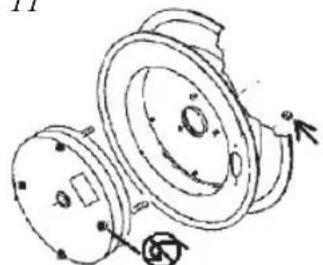
Fig. 11
General Instructions
B-7102 MAIN-SPRING ASSEMBLY REPLACEMENT
To replace model B-7102 main spring:
- Turn off or lockout air/fluid supply to reel and bleed off remaining pressure. Remove supply hose to inlet swivel.
- Remove all tension; see "Tension Adjustment." Unwind hose from reel and remove hose clamp (8mm nut).
- Disconnect metal tube assembly from swivel inlet (11/16" swivel nut).
- Slide flat at wrench provided between spool assembly and support frame onto shaft to hold it from turning during the next step.
- Remove spool from mounting frame (22mm nut)
- Remove inlet swivel assembly by loosening hex end (25mm)
- Remove (4) Phillips head screws and take off outer drum half.
- Remove (3) nuts (10mm).
- Remove then replace main-spring assembly. Install (3) nuts (10mm).
- Reverse procedure to reassemble and re-tension reel (see "Tension Adjustment")
SWIVEL REPLACEMENT
NOTE: Swivel only sold as complete assembly. If o-rings leak, complete swivel must be replaced.
To replace swivel:
- Turn off or lockout air/fluid supply to reel
- Remove all tension from reel (see "Tension Adjustment")
- Disconnect supply hose to swivel
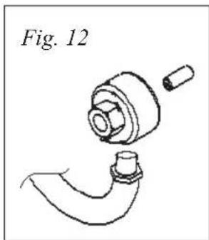
(Fig. 12) Remove swivel by loosening hex end.
Disconnect spool hose or on B-7102 models, the metal tube assembly.
- Reverse above procedure and install new swivel (use
Teflon on tape or sealant on connections; on B-7102 models the metal tube assembled does not require thread sealant)
General Instructions
O-RING REPLACEMENT
CAUTION: Carefully replace o-rings making sure not to damage machined sealing surfaces. O-ring life and sealing ability may otherwise be affected. Hazards or unsafe practices may result in minor personal injury, product or property damage.
To replace o-ring:
- Remove swivel from reels as "Swivel Replacement" procedure
- Remove retaining ring and slowly remove outer swivel from inner shaft
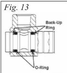
- Remove old o-rings and back-up rings
- (Fig. 13) Install new o-rings and back-up rings, using supplied lubricant
- Reverse above procedure and install new swivel (use Teflon on tape or thread sealant on hose connections; on B-7102 models the metal tube assembly does not require thread sealant)
Preventative Maintenance
HOSE
- Check wear near hose-stop and end fitting. If barb fitting or hose is damaged cut off, hose end and reattach new barb fitting and clamp.
- Check wear along entire hose length. Replace if needed.
SWIVEL
- Check leaks by spraying with soapy water from hand spray bottle. If bubbles form, replace swivel.
ROLLER/HOSEGUIDE
- Check rollers for wear. If rollers on one side have more wear than the other side, then guide position might need re-adjustment.
MOUNTING
- Check tightness of mounting bolts and condition of safety cable/chain and attachment points.
REEMPLACEMENT DU DISPOSITIF DE RESSORT PRINCIPAL
REPLACEMENT DU RACCORD PIVOTANT
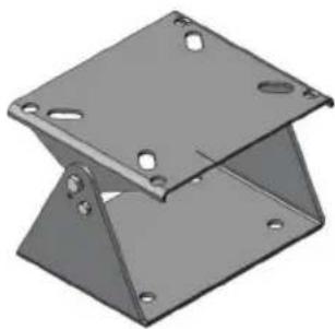
Stainless Steel Swing Bracket
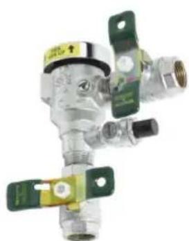
B-0963
Continuous Pressure Vacuum Breaker
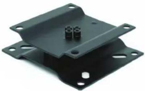
Pivot Bracket
T&S BRASS AND BRONZE WORKS, INC.
A firm commitment to application-engineered plumbing products
2 Saddleback Cove, P.O. Box 1088, T & S Brass-Europe
Travelers Rest, SC 29690 'De Veenhoeve'
- Limited Two Year Warranty
- Attention California Residents:
- Installation and Maintenance Instructions
- B-7000 SERIES EU-7100 SERIES EPOXY POWDER COATED & STAINLESS STEEL REELS
- Part Number Guide
- HOSE KITS - 6
- O-RING KIT - 7
- General Instructions
- Important Safety Instructions
- Installation
- MOUNTING
- MOUNTING B-7102
- General Mounting Requirements
- SECONDARY SUPPORT
- Adjustment
- RATCHET LOCK
- TENSION ADJUSTMENT
- Service
- ENCLOSED HOSE REELS
- HOSE INSTALLATION AND REPLACEMENT
- RATCHET LOCK REPLACEMENT/REMOVAL
- MAIN-SPRING ASSEMBLY REPLACEMENT
- B-7102 MAIN-SPRING ASSEMBLY REPLACEMENT
- SWIVEL REPLACEMENT
- O-RING REPLACEMENT
- Preventative Maintenance
- REEMPLACEMENT DU DISPOSITIF DE RESSORT PRINCIPAL
- REPLACEMENT DU RACCORD PIVOTANT
- T&S BRASS AND BRONZE WORKS, INC.
Brand : T&S
Model : B-7133
Category : Garden hose