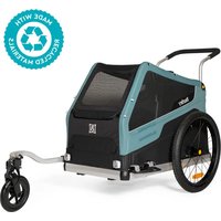
Bark Ranger - Bike trailer Burley - Free user manual and instructions
Find the device manual for free Bark Ranger Burley in PDF.


User questions about Bark Ranger Burley
0 question about this device. Answer the ones you know or ask your own.
Ask a new question about this device
Download the instructions for your Bike trailer in PDF format for free! Find your manual Bark Ranger - Burley and take your electronic device back in hand. On this page are published all the documents necessary for the use of your device. Bark Ranger by Burley.
USER MANUAL Bark Ranger Burley
READ CAREFULLY AND KEEP FOR FUTURE REFERENCE
IMPORTANT
A LIRE ATTENTIVEMENT ET À CONSERVER POUR RÉFÉRENCE ULTÉRIEURE
WICHTIG
BITTE SORGFÄLTIG LESEN UND FÜR SPÄTERES NACHLESEN UNBEDINGT AUFBEWAHREN
IMPORTANTE
LEER DETENIDAMENTE Y MANTENERLAS PARA FUTURAS CONSULTAS
B
Burley®
natural_image
Line drawing of a wheeled cart with wheels and a wheel, no text or symbols presentBark Ranger®
Bark Ranger® XL
OWNER'S INSTRUCTION & SAFETY MANUAL
Contents
ENG
4
INTRODUCTION
8 Maximum Capacities
8 Box Contents
8 Burley Trailer Guide
ASSEMBLY & USE
9 Assembling Your Trailer
10 Closing Your Trailer
11 Attaching and Removing the Wheels
11 Parking Brake Operation
12 Installing the Wheel Guards
12 Installing the Tow Bar
12 Removing the Tow Bar
13 Converting to Stroller Mode
13 Converting to Trailer Mode
13 Installing the Flag
14 Handlebar Installation/Adjustment
15 Connecting Your Trailer to Your Bike
16 Adjusting the Cover
17 Floorboard Removal/Maintenance
17 Brake Adjustment
MAINTENANCE
18 Before You Ride
18 Maintenance
CUSTOMER SERVICE
18 Connect with Burley
18 Product Identification
18 Burley Limited Warranty
DEU
19
EINLEITUNG
The image is too blurry to recognize any text content.

WARNING
FAILURE TO COMPLY WITH THE INSTRUCTIONS AND WARNINGS IN THIS MANUAL COULD RESULT IN SERIOUS INJURY OR DEATH OF THE PASSENGER OR RIDER.

WARNING
ONLY USE WITH A BURLEY APPROVED ACCESSORY. IF ATTACHING AN ACCESSORY TO YOUR TRAILER MAKE SURE TO READ AND FOLLOW ALL WARNINGS AND INSTRUCTIONS THAT ARE INCLUDED WITH THE ACCESSORY KIT.

WARNING
PET MOVEMENT CAN AFFECT THE HANDLING OF YOUR BICYCLE. BE PREPARED FOR SUDDEN MOVEMENTS FROM YOUR PET.
- Never leave the pet unattended.
- DO NOT leash or attach your pet to any part of the trailer
- Ensure that all locking devices are engaged before use.
• To avoid injury, ensure that the pet is kept away when unfolding and folding this product. - NOT intended for use by children. This product is not a toy.
- Make sure pet cannot make contact with the wheel spokes or any other moving parts.
- Be cognizant of exposure hazards to less-active trailer occupants such as windchill and heat exhaustion, either by prolonged exposure in colder temperatures, or by extended periods in warmer temperatures without adequate ventilation or hydration.
- Items placed on top of the unit may cause this product to become unstable. Hazardous conditions may exist if unapproved accessory items are added to this product. Follow Burley cargo guidelines when adding Burley approved accessories.
- Any load attached to the sides of the trailer will affect the stability of the vehicle.
• This product is not suitable for running or skating.
- DO NOT tow trailer with motorized or electric vehicle (approved electric bicycles are okay).
- DO NOT use with a total load that exceeds the weight limits. If recommended load is exceeded, the unit may become unstable.
- DO NOT make modifications to the product.
• DO NOT over-inflate the tires. Failure to comply
with the rated tire sidewall pressure may lead to explosion of the tire and possible injury.
- DO NOT maneuver over stairs or other obstacles while the pet is inside.
- Only use Burley approved accessories. When attaching an accessory to your trailer make sure to read and follow all warnings and instructions that are included with the accessory kit.
- Note: references to the left or right refer to standing behind the trailer looking forward.
- It is recommended that a qualified bicycle mechanic perform a safety check of the towing bicycle before attaching the trailer.
- Before each ride, be sure the trailer does not interfere with braking, pedaling, or steering of the bicycle.
• Always comply with local regulations when using the trailer on public roadways.
- Never ride a bicycle at night without adequate lighting.
- Obey all local legal requirements for lighting.
- The red reflectors that came with the trailer must remain attached and visible on the rear of the trailer at all times.
- If you need to come to a stop for any reason, such as to check on your pet, to make adjustments, or to address a flat tire, be sure to pull off of the road completely.
- When using your trailer, you are towing extra weight and a bigger vehicle. You must allow more time for braking, slowing, stopping, and starting, especially when riding downhill, and allow more room for turns, corners, and passageways.
- Experiment with the loaded trailer in an uncongested area until you become familiar with how your bike handles towing a trailer.
- Avoid rocks, curbs, hard braking, and sudden swerving. Avoid riding over obstacles with one wheel, as this may cause the trailer to tip over.
- Use good judgment when deciding if weather, road or traffic conditions are safe to use a Burley trailer. Recommended temperature limits for using a Burley trailer are 20°F to 100°F (-7°C to 38°C).
- Always ride with the mesh windows securely zipped close to protect pet from flying debris.
- The rider of the bicycle must be at least 16 years old.
- Bicycle trailers pulled by an Electric Powered Assist Cycle (EPAC) can be restricted by law.
- Recommended speed limits:
- 15 mph (24 km/h) on smooth, straight roads
- 5 mph (8 km/h) when turning or on uneven roads
- Trailer weight must be properly distributed for safe handling. The downward force at the end of the tow bar, where it meets the bike, should be between 2 lbs and 20 lbs (1 and 9 kg). To measure this, load your trailer and place next to bathroom scale. Step on scale and note your weight. While on scale, lift up the end of the towbar 1 foot (30 cm) off the ground and note weight again. The weight difference is the downwards force on the tow bar. If the weight is too low, the rear wheel of the bicycle could lose traction. If it is too high the hitch may be overloaded.

WARNHINWEIS
Bark Ranger: 25 in (63.5 cm)
Bark Ranger XL: 34 in (86 cm)
Maximum Standing
Pet Length
Bark Ranger: 29 in (73 cm)
Bark Ranger XL: 33 in (83 cm)
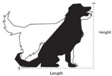
text_image
Height LengthWARNING
ALWAYS COMPLY WITH LOCAL REGULATIONS FOR MAXIMUM TRAILER WEIGHT.
Box Contents

text_image
1 Trailer 1 Flag 2 Wheels 1 Handlebar 2 Wheel Guards 1 Tow Bar/ 1-Wheel Stroller & HitchBurley Trailer Guide
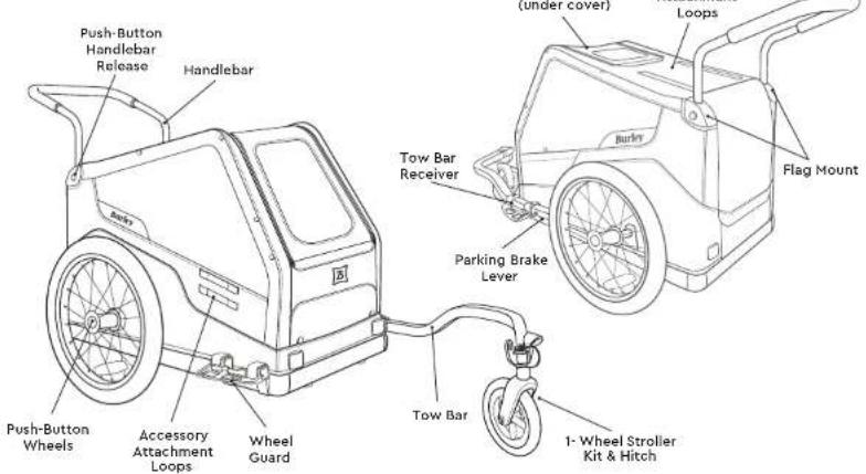
text_image
Push-Button Handlebar Release Handlebar Push-Button Wheels Accessory Attachment Loops Wheel Guard Tow Bar Receiver Parking Brake Lever Tow Bar 1-Wheel Stroller Kit & Hitch Flag Mount (under cover) LoopsAssembling Your Trailer
natural_image
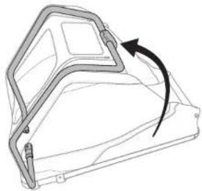
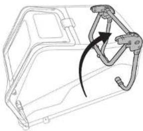
Technical line drawing of a mechanical component with an arrow indicating rotational motion (no text or symbols)1
Rotate the front frame tube towards the front of the trailer.
natural_image
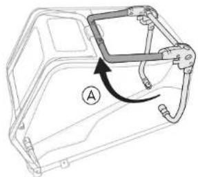
Technical line drawing of a vehicle chassis frame with no visible text or symbols2
Rotate the rear frame tube towards the rear of the trailer.
natural_image
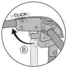
Technical line drawing of a mechanical bracket with a curved arrow indicating rotation (no text or symbols)3
text_image
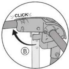
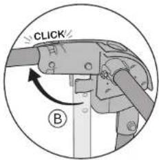
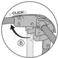
CLICK BRotate the middle frame tube upwards (A) until the frame buttons click into place (B).
natural_image
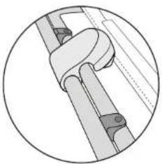
Mechanical assembly diagram showing a clamping mechanism with no visible text or symbols4
Align the front frame with the middle frame so that the front frame tube sits in the black plastic saddles.
natural_image
Illustration of a hand using a tool to adjust or install a mechanical component, with an arrow indicating rotation (no text or symbols present)5
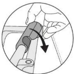
Secure the trailer frame by rotating the frame latch down until it snaps into place. Give the frame a slight tug upwards to ensure that the frame latch is engaged.

WARNING
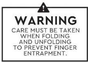
CARE MUST BE TAKEN WHEN FOLDING AND UNFOLDING TO PREVENT FINGER ENTRAPMENT.

BARK RANGER & BARK RANGER XL
ENOD ASSEMBLY & USE
Closing Your Trailer
text_image
WARNING CARE MUST BE TAKEN WHEN FOLDING AND UNFOLDING TO PREVENT FINGER ENTRAPMENT.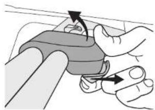
natural_image
Illustration of hands performing a manual task on a curved object, with arrows indicating motion direction (no text or symbols)1
Remove all contents from the interior and exterior of the trailer, including the handlebar (see Handlebar Installation/Adjustment section). Release frame latch by pulling the yellow slider back to disengage the locking mechanism, and rotate upwards.
text_image
Diagram showing hands using a tool to press or mark a finger, with an arrow and labeled point A indicating a specific step.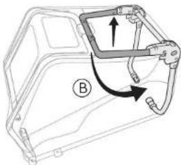
natural_image
Technical line drawing of a mechanical housing component with arrows indicating motion (no text or symbols)2
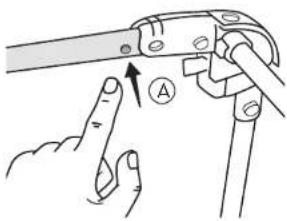
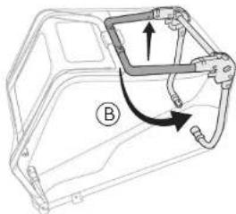
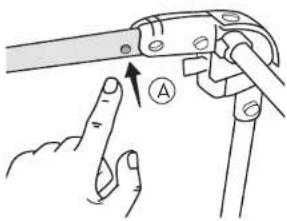
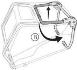
From the rear of the trailer, depress and hold the right and left frame buttonsⒶ, and rotate the middle frame member downwards until it snaps into place Ⓑ.
natural_image
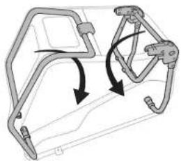
Diagram of a vehicle chassis frame with directional arrows indicating movement or force (no text or symbols)Fold the rear frame down, followed by the front frame.
Attaching & Removing the Wheels
natural_image
Diagram showing a mechanical assembly with a shaft and gear mechanism (no text or labels)1
natural_image
Hand holding a bicycle wheel with spokes, no text or symbols visible2
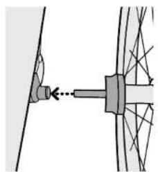
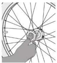
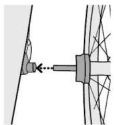
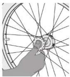
While pressing rubber button, insert wheel axle into axle receiver, and then release the button. Pull firmly on wheel to confirm the axle is fully engaged.
For removing wheel; while pressing button, slide wheel out of the axle receiver. Release button.
Parking Brake Operation

WARNING
THE PARKING BRAKE IS ONLY INTENDED TO BE USED WHEN THE TRAILER IS AT A COMPLETE STOP. USE OF THE PARKING BRAKE WHILE IN MOTION CAN RESULT IN DAMAGE, AN ACCIDENT, SERIOUS INJURY, OR DEATH.
natural_image
Illustration of a hand using a tool to adjust or install a mechanical component (no text or symbols visible)1
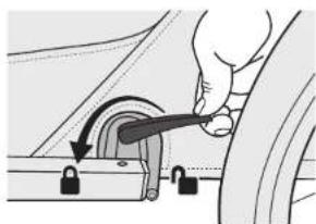
Ensure the trailer is at a complete stop. Rotate the red parking brake lever so that it points towards the front of the trailer. The trailer may need to roll forward slightly for the brake to engage, and the lever to fully rotate.
natural_image
Illustration of a hand using a tool to adjust or install a mechanical component (no text or symbols visible)2
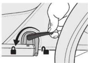
To disengage the parking brake, fully rotate the lever so that it points towards the rear of the trailer.

BARK RANGER & BARK RANGER XL

Installing the Wheel Guards
natural_image
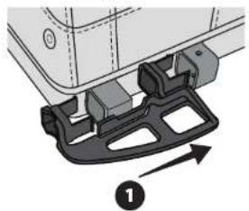
Mechanical assembly diagram showing a bracket with mounting holes and a labeled component (no text or symbols present)Align the wheel guards with the tow bar reciever.
natural_image
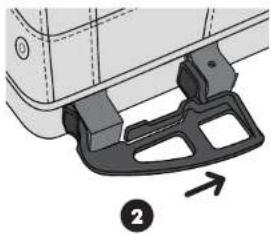
Mechanical component diagram showing a bracket and mounting bracket with an arrow indicating direction (no text or symbols)Slide the wheel guard into the tow bar receiver until it snaps into place. Lightly bend front tabs inward when inserting.
natural_image
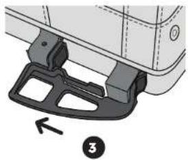
Mechanical component diagram showing a bracket with a numbered arrow and label (no text or symbols present)Repeat on the opposite side.
Installing the Tow Bar
text_image
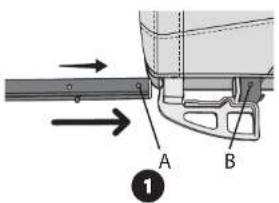
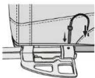
A B ①Slide the tow bar into the tow bar receivers until the first hole is aligned with the hole in the rear receiver. The red safety collar should be flush with the front of the tow bar receiver, which indicates that the tow bar has been fully inserted.
natural_image
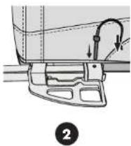
Mechanical assembly diagram showing a lever mechanism with arrows indicating motion (no text or symbols)Insert the retaining pin from the top through the aligned holes
natural_image
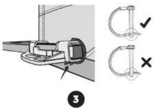
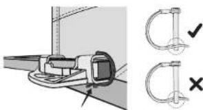
Technical illustration of a mechanical clamp or bracket assembly with two cross symbols (✓ and ×) indicating inspection or repair points, no text or labels present.Make sure the retaining pin has locked properly as shown.
Removing the
Tow Bar
natural_image
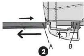
Mechanical assembly diagram showing a lever mechanism with an arrow indicating direction (no text or labels present)Remove the retaining pin.
text_image
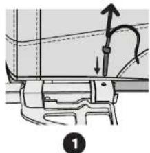
Technical diagram showing mechanical assembly with labeled parts A and B, including directional arrows and a numbered annotation.Press the tab on the wheel guard to depress the detent. Remove the tow bar.
Converting to Stroller Mode
natural_image
Mechanical diagram showing two stages of a bicycle steering wheel and wheel assembly (no text or symbols)1
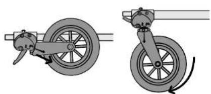
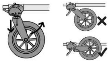
Pull fork as shown, then rotate wheel down fully. Fork will automatically secure into the locked position.
Converting to Trailer Mode
text_image
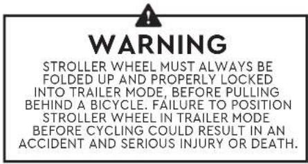
WARNING STROLLER WHEEL MUST ALWAYS BE FOLDED UP AND PROPERLY LOCKED INTO TRAILER MODE, BEFORE PULLING BEHIND A BICYCLE. FAILURE TO POSITION STROLLER WHEEL IN TRAILER MODE BEFORE CYCLING COULD RESULT IN AN ACCIDENT AND SERIOUS INJURY OR DEATH.note
The black tab that extends from the stroller mount towards the flex connector is not a lever. It is a safety mechanism to prevent the attachment of the trailer to a bicycle while the stroller wheel is in its downward (strolling) position.
text_image
Diagram illustrating bicycle wheel and bicycle suspension system with labeled components and directional arrows1
Pull fork down and rotate up into trailer mode as shown. Fork will automatically lock into trailer position when positioned correctly.
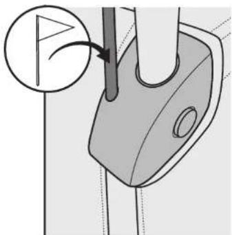
Insert the flag into the flag mount located on either handlebar receiver. Ensure it is inserted completely.
Flag Installation
1
natural_image
Diagram of a golf club's handle and gear mechanism, showing part positioning and cutting tool (no text or symbols)
BARK RANGER & BARK RANGER XL

ASSEMBLY & USE
Handlebar Installation/Adjustment

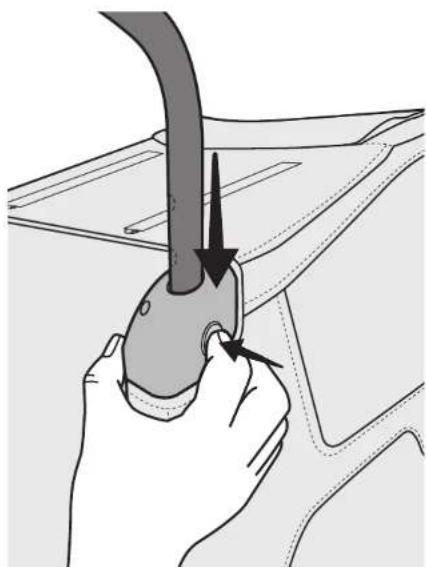
Insert handlebar into receiver, depress both yellow handlebar receiver buttons and insert the handlebar past the buttons.

Release the buttons and slide the handlebar until it clicks into place.

The handlebar has two height settings. Depress each handlebar receiver button to slide the handlebar to desired setting. Ensure that both sides of handlebar are in the same height setting.

Before use, push down and then pull up slightly on the handlebar grip to ensure that the handlebar is locked into place.

To remove handlebar, depress both buttons and slide handlebar out completely.
natural_image
Illustration of a hand holding a car hood with a curved pipe inserted, showing mechanical components (no text or symbols)Connecting Your Trailer to Your Bike Disconnecting Your
note
To identify your bike's rear axle, see the Hitch Guide on Burley.com/hitching-guide or confirm with your local bike shop
natural_image
Mechanical diagram showing a wheel and gear assembly with no visible text or symbols1
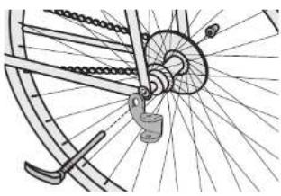
Quick Release or Nutted Axle:
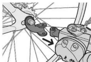
Remove quick release skewer or axle nut from left side of bike's rear-wheel. Install the hitch between quick release or axle nut and frame with the hitch tabs parallel to ground. Tighten quick release or axle nut following bike manufacturer's recommendation. Consult Burley.com for adapters designed to help fit your trailer to your bike if necessary.
Thru Axle:
Requires adapted thru axle to install hitch. Consult Burley.com to obtain proper fit and installation to your bike.
natural_image
Diagram of a mechanical assembly with gears and shafts, no visible text or symbols2
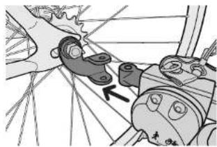
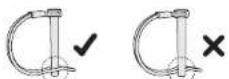
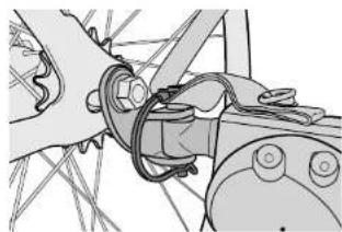
Connecting the tow bar to the hitch: Insert flex connector between the two tabs of the hitch, such that all the holes are aligned. Insert the retaining pin through the holes from the top and close the retainer at the bottom.
text_image
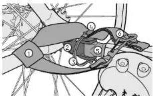
Technical diagram of a mechanical linkage or clamping device with numbered components and labeled parts- Safety strap
- Hitch
- Retainer
- Retaining Pin
- Flex Connector
- Clasp
natural_image
Diagram of a bicycle seatbelt with a belt and control panel (no text or symbols)3
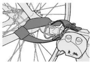
Wrap safety strap around the frame of the bike and secure the clasp to the D-ring on the tow bar. Ensure the strap is tight and cannot be caught in other components.

WARNING
ONCE INSTALLED, ENSURE THE SAFETY STRAP DOES NOT COME INTO CONTACT WITH ANY MOVING PARTS SUCH AS THE DISC BRAKE ROTOR OR SPOKES.
Trailer From
Your Bike
natural_image
Mechanical assembly diagram showing a linkage mechanism with no visible text or symbols1
Unfasten the clasp from the D-Ring and unwrap the safety strap from the frame of the bike. Open the retainer on the retaining pin and pull it upwards to remove it.
natural_image
Mechanical assembly diagram showing gear and motor components (no text or labels)2
Remove the flex connector from the hitch by pulling away from the bike.
note
The hitch can remain on the bike when trailer is removed.

BARK RANGER & BARK RANGER XL

Adjusting the Cover

natural_image
Technical illustration of a mechanical component with a magnified inset showing a hand adjusting a small component (no text or symbols present)1
The front mesh window can be unzipped, rolled, and fastened by inserting the door hooks in the reflective loops at location A.
natural_image
Line drawing of a mechanical device with a handle and circular base (no text or symbols)2
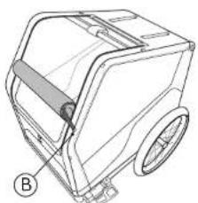
The front mesh window can be unzipped and rolled from the roof of the trailer. Fasten the window by inserting the window hooks in the reflective loops at location ⑧.
natural_image
Technical line drawing of a mechanical device with labeled component (C), no readable text or symbols present.3
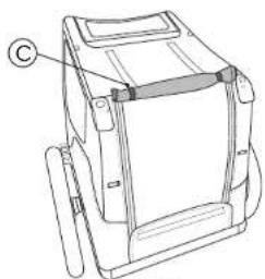
The rear trailer door cover can be rolled and secured by inserting the hanging hooks in the reflective loops at location ©.
natural_image
Technical line drawing of a mechanical device with labeled component (C), no readable text or symbols present4
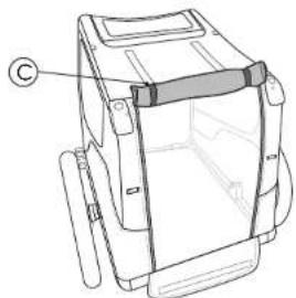
The rear door mesh window can be rolled and secured by inserting the hanging hooks in the reflective loops at location ©.
note
Ensure that doors are secured prior to using the trailer in bike or stroller mode.
Floorboard Removal/Maintenance
natural_image
Technical line drawing of a mechanical device with an arrow indicating direction (no text or symbols)1
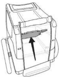
From the back of the trailer, push the bottom of the floorboard upwards towards the inside of the trailer, on both corners, until it snaps past the plastic retainers.
2
Rotate floorboard upwards and slide towards the back of the trailer to remove.
3
Reinstall by sliding front of the floorboard under front frame tubes and rotating downwards.
4
Push floorboard firmly down and ensure all snaps are engaged on floorboard.
Brake Adjustment
text_image
≥10mmnote
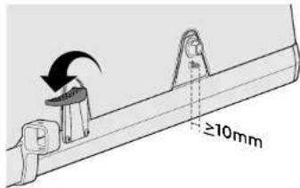
Brake cables may stretch over time with product usage. Follow the steps below for any needed adjustment to ensure proper brake activation.
1
Remove the wheels and activate the brake lever. The brake pins should protrude a minimum of 10mm. If less than 10mm, they will need to be adjusted to ensure proper brake function.
natural_image
Mechanical assembly diagram showing a lever mechanism with a labeled component (A), no text or symbols present.2
To adjust the brake pin protrusion:
Release the brake and remove the floorboard.
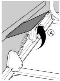
Raise the brake cable flap on the brake lever side of the trailer A.
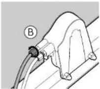
Adjust the cable by rotating the barrel adjuster counterclockwise to tighten the cable Ⓑ.
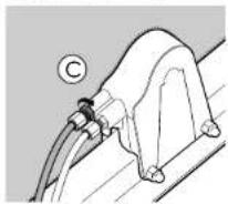
Rotate the left barrel adjuster for the left-side brake and the right barrel adjuster for the right-side brake.
Secure the adjuster by tightening the nut against the plastic housing using an 8mm wrench Ⓐ.
Activate the brake lever and check for 10mm of brake pin protrusion.
3
Release the brake and activate it to ensure proper function.
4
Lower the brake cable flap and replace the floorboard.

BARK RANGER & BARK RANGER XL
ENOD ASSEMBLY & USE
Before You Ride
Contact your authorized Burley dealer or Burley.com for replacement of any damaged or worn parts.
Check before each use
- Wheels are properly secured to the trailer.
o Tires are inflated to recommended pressure on the tire sidewall.
o Tow bar is properly secured to the trailer.
o Hitch is properly secured to the bicycle.
o Hitch retaining pin is secured and safety strap is attached.
o Tow Bar Receiver retaining pin is secured and safety strap is attached.
o Load does not exceed:
Bark Ranger: 75 lbs (34 kg)
- Bark Ranger XL: 100 lbs (45 kg)
o Weight of tow bar at hitch is greater than 2 lbs (1 kg) but does not exceed 20 lbs (9 kg) with fully loaded trailer.
o Bicycle is in proper working order, especially brakes and tires (refer to bicycle manufacturer's instructions).
o Safety flag is in place.
- Cover is installed and closed.
o Lighting is adequate for riding conditions.
Check monthly
o Inspect tow bar, hitch, frame tubing, flex connector and hardware for damage
○ Check that bolts are tight
○ Inspect tires and wheels for wear, cracks and trueness
○ Inspect fabric parts for rips, abrasions, and missing or damaged hardware
Service
o Flex Connectors need to be serviced every 3-5 years for safe operation
Maintenance
Storage
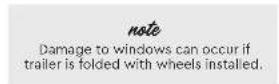
For longer product life, store trailer indoors. If trailer is stored outdoors, protect the trailer with a Burley Storage Cover or a Trailer Storage Bag. The trailer should not be stored at temperatures less than -10°F (-23°C) or greater than 150°F (65°C). Tires should not be stored in contact with windows as window discoloration may result.
Fabric Care
Hand wash fabric parts with warm water and mild soap. DO NOT use bleach or solvents. Hang dry trailer cover. Wipe dry and store out of direct sunlight in a dry, well-ventilated area. Clean windows with a damp, soft cloth.
Connect with Burley
Whether you ride your bike all year long or are a fair weather rider, Burley shares your enthusiasm for making the most of your bike. Thank you for your business. We appreciate it.
Product Identification
If you have any questions about the model name or year of your Burley, please consult our product identification web page: burley.com/support/what-year-is-my-burley
Burley Limited Warranty
This Burley trailer is warranted from the date of purchase against defects in materials and workmanship as follows: fabric parts for one year, frame and plastic parts for three years. Your original dated sales or delivery receipt showing the date of purchase is your proof of purchase. If a defect in materials or workmanship is discovered during the Limited Warranty period, we will, at our sale option, repair or replace your product at no cost to you. This warranty is only valid in the country in which the product was purchased. The Limited Warranty extends only to the original retail purchaser of this product and is not transferable to anyone who obtains ownership of the product from the original purchaser. The Limited Warranty does not cover claims resulting from misuse, failure to follow the instructions, installation, improper maintenance and use, abuse alteration, involvement in an accident, and normal wear and tear. The Limited Warranty does not cover products which are used in rental operations and Burley will not be liable for any incidental or commercial damages relating to such use. TO THE GREATEST EXTENT PERMITTED BY LAW, THIS LIMITED WARRANTY IS EXCLUSIVE AND IN LIEU OF ANY OTHER WARRANTY, WRITTEN OR DRAL, INCLUDING BUT NOT LIMITED TO ANY EXPRESS OR IMPLIED WARRANTY OF MERCHANTABILITY OR FITNESS FOR A PARTICULAR PURPOSE. The duration of any implied warranties, including any implied warranty of merchantability or fitness for a particular purpose that may exist during the express warranty period are expressly limited to the limited warranty period. Some states and countries do not allow limitations on how long an implied limited warranty lasts, therefore, the above limitation and exclusions may not apply to you.
THE CUSTOMER'S EXCLUSIVE REMEDY FOR BREACH OF THIS LIMITED WARRANTY OR OF ANY IMPLIED WARRANTY OR OF ANY OTHER OBLIGATION ARISING BY OPERATION OF LAW OR OTHERWISE SHALL BE LIMITED AS SPECIFIED HEREIN TO REPAIR OR REPLACEMENT, AT OUR SOUL OPTION IN ANY EVENT, RESPONSIBILITY FOR SPECIAL, INCIDENTAL AND CONSEQUENTIAL DAMAGES IS EXPRESSLY EXCLUDED. Some states do not allow the exclusion of limitation of incidental or consequential damages, so the above limitation of exclusion may not apply to you. Our goods come with guarantees that cannot be excluded under the Australian Consumer Law. You are entitled to a replacement or refund for a major failure and for compensation for any other reasonably foreseeable loss or damage. You are also entitled to have the good repaired or replaced if the goods fail to be of acceptable quality and the failure does not amount to a major failure. This Limited Warranty gives you specific legal rights, and you may have other rights that vary from state to state or country. For warranty service or replacement part information for the USA or Canada, please contact Burley directly by calling 800-331-5294 or emailing burley@burley.com. For warranty service or replacement part information outside of the USA and Canada please contact the place of purchase for warranty service. Please be prepared to provide the product model, serial number and a description of the warranty issue. Some replacement parts may be available for purchase after this limited warranty expires. Please visit us at www.burley.com or call us at 541 687-1844 for more information.
text_image
Height LengthWARNHINWEIS
BEFOLGEN SIE STETS LOKALE
natural_image
Technical line drawing of a mechanical component with an arrow indicating rotational motion (no text or symbols)natural_image
Line drawing of a vehicle chassis frame with a curved arrow indicating rotation (no text or symbols)natural_image
Technical line drawing of a mechanical component with no visible text or symbols3
text_image
CLICK Bnatural_image
Cross-sectional diagram of a mechanical joint or clamping mechanism (no text or symbols)natural_image
Illustration of a hand using a tool to adjust or install a mechanical component, with an arrow indicating rotation (no text or symbols present)natural_image
Illustration of hands performing a finger manipulation or tooling task (no text or symbols visible)1
text_image
Diagram showing hands using a tool to press or mark a component, with labeled point A and directional arrow2
natural_image
Technical line drawing of a mechanical housing component with directional arrows indicating movement (no text or symbols)natural_image
Diagram of a vehicle chassis frame with directional arrows indicating motion (no text or symbols)3
Attaching & Removing the Wheels
natural_image
Diagram showing a mechanical assembly with a shaft and gear mechanism (no text or symbols)natural_image
Hand holding a bicycle wheel with visible spokes and hub (no text or symbols)natural_image
Illustration of a hand using a tool to adjust or install a mechanical component (no text or symbols visible)natural_image
Illustration of a hand using a tool to adjust or install a mechanical component (no text or symbols visible)natural_image
Mechanical assembly diagram showing a bracket with mounting holes and a labeled component (no text or symbols present)natural_image
Mechanical component diagram showing a bracket and mounting bracket with an arrow indicating direction (no text or symbols)natural_image
Mechanical component diagram showing a bracket with a numbered arrow and label (no text or symbols present)text_image
Technical diagram showing mechanical assembly with labeled parts A and B, and directional arrows indicating motion or force.natural_image
Technical illustration of a mechanical clamp or bracket assembly with two cross symbols (no text or labels)natural_image
Mechanical assembly diagram showing a lever mechanism with an arrow indicating direction (no text or symbols present)text_image
Technical diagram showing mechanical assembly with labeled parts A and B, including directional arrows and numbered annotation.natural_image
Mechanical diagram showing two stages of a bicycle steering wheel assembly, with no text or symbols present.text_image
Diagram illustrating bicycle wheel and bicycle suspension system with labeled correct and incorrect statesnatural_image
Diagram of a golf club handle and gear mechanism (no text or symbols)natural_image
Illustration of a hand holding a car hood with a curved pipe inserted, showing mechanical components (no text or symbols)
BARK RANGER & BARK RANGER XL
natural_image
Mechanical diagram showing a bicycle wheel and gear assembly (no text or labels)natural_image
Diagram of a mechanical assembly with gears and shafts, no visible text or symbolstext_image
Technical diagram of a mechanical assembly with numbered components, likely for engineering or manufacturing documentation.natural_image
Diagram of a bicycle seatbelt with a belt and control panel (no text or symbols)natural_image
Mechanical assembly diagram showing a linkage mechanism with no visible text or symbolsnatural_image
Mechanical assembly diagram showing a gear mechanism with no visible text or symbolsnatural_image
Technical line drawing of a mechanical component with an inset showing a hand adjusting a piece (no text or symbols present)1
natural_image
Technical line drawing of a mechanical device with no visible text or symbols2
natural_image
Technical line drawing of a mechanical device with labeled component (C), no readable text or symbols present3
natural_image
Technical line drawing of a mechanical device with labeled component (C), no readable text or symbols present.4
natural_image
Diagram of a device casing with an arrow indicating direction (no text or symbols present)1
text_image
Technical diagram showing mechanical assembly with labeled components and directional arrow2
natural_image
Technical line drawing of a mechanical component with an arrow indicating rotational motion (no text or symbols)natural_image
Technical line drawing of a vehicle chassis frame with no visible text or symbolsnatural_image
Technical line drawing of a mechanical component with no visible text or symbols3
text_image
CLICK Bnatural_image
Cross-sectional diagram of a mechanical joint or connector (no text or symbols visible)natural_image
Illustration of a hand using a tool to adjust or install a mechanical component, with an arrow indicating rotation (no text or symbols present)natural_image
Illustration of hands performing a finger manipulation or tooling task (no text or symbols visible)1
text_image
Diagram showing hands using a tool to press or mark a component, with labeled point A and directional arrow2
natural_image
Technical line drawing of a mechanical housing component with labeled parts (no text or symbols)natural_image
Diagram of a vehicle chassis frame with directional arrows indicating movement (no text or symbols)3
natural_image
Diagram of a mechanical assembly with a shaft and gear mechanism (no text or symbols)1
natural_image
Hand holding a bicycle wheel with spokes, no text or symbols visible2
natural_image
Illustration of a hand using a tool to adjust or install a mechanical component, with no visible text or symbols.1
natural_image
Illustration of a hand using a tool to adjust or install a mechanical component (no text or symbols visible)2
text_image
Technical diagram showing mechanical assembly with labeled parts A and B, and directional arrows indicating motion or force.1
2
natural_image
Technical diagram showing mechanical assembly with two cross-sectional views (no text or symbols)natural_image
Mechanical diagram showing a lever mechanism with arrows indicating direction (no text or symbols)text_image
Technical diagram showing mechanical assembly with labeled parts A and B, and directional arrows indicating motion or force.natural_image
Mechanical diagram showing two stages of a bicycle steering wheel and wheel assembly (no text or symbols)text_image
Diagram illustrating bicycle wheel turning and disassembly steps, showing gear rotation and wheel movement with labels X and Y.natural_image
Technical diagram of a golf club handle with a circular arrow indicating a specific part (no text or symbols present)
BARK RANGER & BARK RANGER XL

ASSEMB

UTILISATION
natural_image
Illustration of a hand holding a car hood with a curved pipe inserted, showing mechanical components (no text or symbols)natural_image
Mechanical diagram showing a wheel and gear assembly with no visible text or symbolsnatural_image
Diagram of a mechanical assembly with gears and rods, no visible text or symbolstext_image
Technical diagram of a mechanical assembly with numbered components, likely for engineering or manufacturing documentation.natural_image
Diagram of a bicycle seatbelt with a belt and control panel (no text or symbols)natural_image
Mechanical assembly diagram showing a linkage mechanism with no visible text or symbolsnatural_image
Mechanical diagram showing a bicycle wheel assembly with gear and pulley (no text or labels)natural_image
Technical illustration of a hand operating a sewing machine component, showing a close-up view with no text or symbols.1
natural_image
Technical line drawing of a mechanical device with no visible text or symbols2
natural_image
Technical line drawing of a mechanical device with labeled component (no text or symbols present)3
natural_image
Technical line drawing of a mechanical device with labeled component (C), no readable text or symbols present.4
natural_image
Technical line drawing of a mechanical device with an arrow indicating a component (no text or symbols present)1
natural_image
Mechanical assembly diagram showing a lever mechanism with a labeled component (A), no text or symbols present.2
natural_image
Technical line drawing of a mechanical component with an arrow indicating rotational motion (no text or symbols)natural_image
Technical line drawing of a vehicle chassis frame with a curved arrow indicating rotation (no text or symbols)natural_image
Technical line drawing of a mechanical component with no visible text or symbols3
text_image
CLICK Bnatural_image
Diagram of a mechanical clamp or bracket assembly (no text or symbols visible)natural_image
Illustration of a hand adjusting a mechanical component with an arrow indicating rotation (no text or symbols present)natural_image
Illustration of hands performing a finger manipulation or tooling task (no text or symbols visible)1
text_image
Diagram showing hands using a tool to press or mark a component, with labeled point A and directional arrow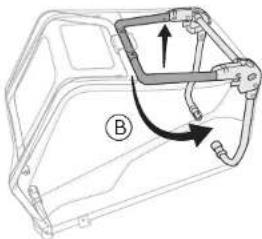
natural_image
Technical line drawing of a mechanical housing component with directional arrows indicating movement (no text or symbols)2
natural_image
Mechanical component diagram showing two curved arms with arrows indicating rotation or movement (no text or symbols)natural_image
Pure mechanical diagram showing a shaft and gear assembly without any text, numbers, or symbols1
natural_image
Hand holding a bicycle wheel with spokes, no text or symbols visible2
natural_image
Illustration of a hand using a tool to adjust or install a mechanical component, with no visible text or symbols.1
natural_image
Hand holding a lever mechanism with a curved arrow indicating motion (no text or symbols)2
natural_image
Mechanical assembly diagram showing a bracket with mounting holes and a labeled component (no text or symbols present)natural_image
Mechanical component diagram showing a bracket and mounting bracket with an arrow indicating direction (no text or symbols)natural_image
Mechanical component diagram showing a bracket with a highlighted part and directional arrow (no text or symbols)natural_image
Diagram of a car door handle with arrows indicating movement or force (no text or symbols)natural_image
Technical illustration of a mechanical clamp or bracket assembly with two cross symbols indicating inspection or failure (no text or labels present)natural_image
Mechanical assembly diagram showing a lever mechanism with an arrow indicating direction (no text or symbols present)text_image
Technical diagram showing mechanical assembly with labeled parts A and B, including directional arrows and a numbered marker.natural_image
Mechanical diagram showing two bicycle wheel assembly steps with rotation arrows (no text or labels)1
natural_image
Diagram of a golf club handle with a circular arrow pointing to the tip, no text or symbols presentnatural_image
Illustration of a hand holding a tool with a curved tube inserted, showing mechanical components (no text or symbols)
BARK RANGER & BARK RANGER XL

natural_image
Mechanical diagram showing a wheel and gear assembly with no visible text or symbols1
natural_image
Diagram of a mechanical assembly with gears and rods, no visible text or symbols2
text_image
Technical diagram of a mechanical linkage or clamping device with numbered components and labeled partsnatural_image
Diagram of a bicycle seatbelt with a belt and control panel (no text or symbols)3
natural_image
Mechanical assembly diagram showing a linkage mechanism with no visible text or symbols1
natural_image
Mechanical assembly diagram showing gear and motor components (no text or labels)2
natural_image
Technical line drawing of a mechanical component with an inset showing a hand holding a tool (no text or symbols present)1
natural_image
Technical line drawing of a mechanical device with no visible text or symbols2
natural_image
Technical line drawing of a mechanical device with labeled component (C), no readable text or symbols present3
natural_image
Technical line drawing of a mechanical device with labeled component (C), no readable text or symbols present.4
natural_image
Diagram of a device casing with an arrow indicating direction (no text or symbols present)1
natural_image
Mechanical assembly diagram showing a lever mechanism with a labeled component (A), no text or symbols present.2
1500 Westec Drive | Eugene, OR 97402 USA
P. 541.687.1644 or 800.423.8445 | F. 541.687.0436
burley@burley.com | Burley.com
©2024 Burley Design LLC
"Burley" is a registered trademark of Burley Design LLC | MAN-00001_01