MF 2503CEI - Fan Melchioni - Free user manual and instructions
Find the device manual for free MF 2503CEI Melchioni in PDF.


| Product type | Ceiling fan with LED lighting |
| Brand | Melchioni |
| Model | MF 2503CEI |
| Dimensions (L x H x D) | 102 x 46 x 102 cm |
| Weight | 6.5 kg |
| Power supply | 220-240 V AC, 50 Hz |
| Maximum power | 65 W |
| Rotation speeds | 6 adjustable speeds |
| Main functions | Natural ventilation, reverse rotation, programmable delayed shutdown (1-8 h), LED lighting with variable color temperature (warm, neutral, cool) |
| Minimum installation height | 230 cm from the floor (bottom edge of blades) |
| Distance from walls | At least 50 cm on each side of the blades |
| Control | Radio remote control (range not specified) |
| Remote control batteries | Not supplied, replace periodically |
| Cleaning | Damp cloth, no abrasive cleaners; disconnect power before |
| Maintenance | Replacement of remote control batteries; dynamic balancing possible |
| Material | Not specified in the manual (presumably metal and plastic) |
| Warranty | 2 years conventional, covers manufacturing defects |
| Repairability | Do not repair yourself; contact a qualified technician |
| Spare parts | Contact the dealer for missing or damaged parts |
| Safety | Do not use outdoors, near water or heat sources; keep out of reach of children under 8 years |
| Standards | Compliant with directives 2014/30/EU, 2014/35/EU, 2009/125/EC, 2011/65/EU |
| Intended use | Domestic, indoor only |
Frequently Asked Questions - MF 2503CEI Melchioni
User questions about MF 2503CEI Melchioni
0 question about this device. Answer the ones you know or ask your own.
Ask a new question about this device
Download the instructions for your Fan in PDF format for free! Find your manual MF 2503CEI - Melchioni and take your electronic device back in hand. On this page are published all the documents necessary for the use of your device. MF 2503CEI by Melchioni.
USER MANUAL MF 2503CEI Melchioni
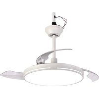
Ceiling stirrer with LED light
natural_image
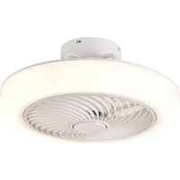
Modern white overhead fan with three blades and a circular base (no text or symbols)IT Manuale d'uso 1
EN User manual 15
natural_image
Technical line drawings of various household appliances and fixtures (no text or symbols)natural_image
Line drawings of five different tools: a cylindrical pipe, a wrench, screwdriver, a pliers, and a triangular ruler (no text or symbols present)FISSAGGIO A SOFFITTO IN LEGNO:

natural_image
Technical line drawing of a mechanical assembly with mounting holes and mounting fasteners (no text or symbols)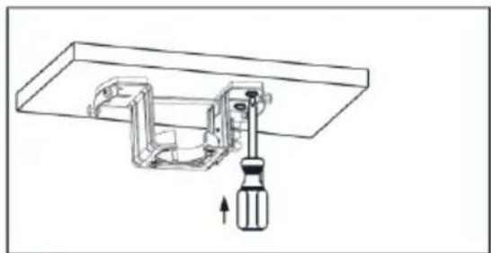
natural_image
Technical line drawing of a mechanical assembly with a screwdriver inserted into a housing (no text or symbols)natural_image
Technical line drawing of a mechanical assembly with mounting holes and internal components (no text or symbols)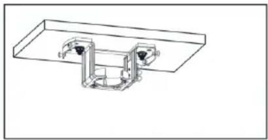
natural_image
Technical line drawing of a mechanical assembly with two mounting brackets (no text or symbols)natural_image
Diagram of a mechanical device with a funnel and base, showing directional arrows indicating movement or force (no text or symbols present)natural_image
Technical line drawing of a mechanical assembly with a component and a close-up inset showing internal components (no text or symbols)text_image
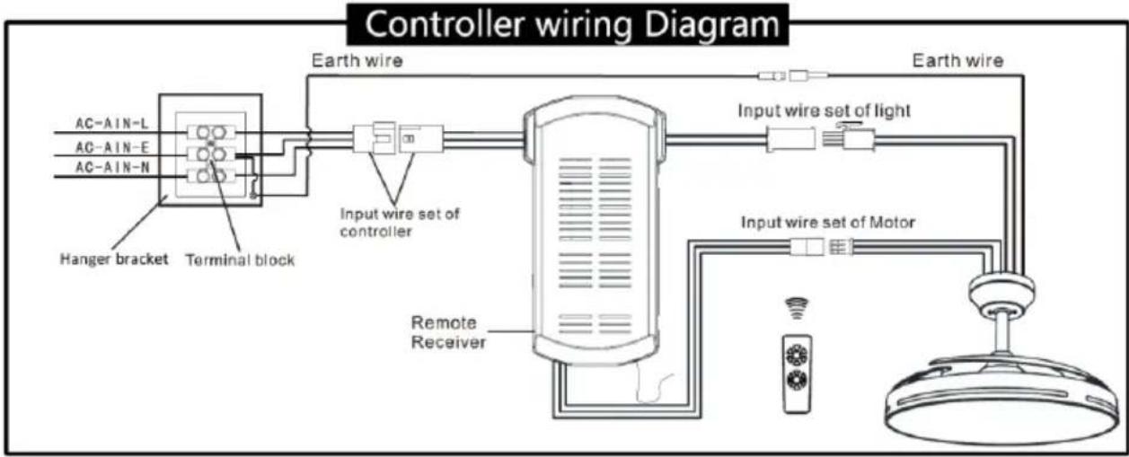
Controller wiring Diagram AC-AIN-L AC-AIN-E AC-AIN-N Hanger bracket Terminal block Earth wire Input wire set of controller Remote Receiver Input wire set of light Input wire set of MotorRemote receiver = Centralina
AC-A IN-L = Fase
AC-A IN-E = Terra
AC-A IN-N = Neutro
natural_image
Technical line drawing of a mechanical component with no visible text or symbols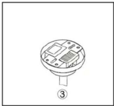
natural_image
Technical line drawing of a mechanical component with labeled part (3), no text or symbols presenttext_image
Technical diagram showing a ceiling structure with an arrow indicating rotation and a detailed interior layout below.natural_image
Technical line drawing of a ceiling-mounted device with internal components and an upward arrow indicating motion (no text or symbols)natural_image
Line drawing of a fan with blades and a funnel, showing mechanical components (no text or symbols)Melchioni S.p.a., owner of the Melchioni Family brand, thanks you for purchasing this appliance. It is the result of a careful selection of features and the meticulous refinement of details, with the aim of offering a complete, versatile, reliable and high-performance solution for both the occasional and the most demanding users.
This manual contains important information both for the correct use of the appliance and for its safe operation. It is essential to read and understand its contents before performing any operations in order to obtain the best performance from the appliance. Keep this manual even after reading it, as you may need to refer to it in the future.
The Melchioni Family team is at your disposal for any advice, instructions or suggestions.
2. IMPORTANT INFORMATION FOR CORRECT, SAFE USE OF THE APPLIANCE
The following instructions must be read, understood and complied with before commissioning the appliance. They are especially useful for the protection of the safety, physical conditions and security of the operator and persons nearby, as well as for providing valuable information for preventing faults and malfunctions, for prolonging the service life, for reducing energy consumption and for environmental protection.
- The appliance is designed for household and non-intensive use. Any professional use compromises the safety requirement and is a condition for inapplicability of the warranty.
- The product is not designed for operation in industrial environments, large commercial areas, large public or community areas, basements, garages, garrets, pergolas, porches or other locations where it may be exposed to the elements.
- The appliance is intended for indoor use and protected from inclement weather: use in an outdoor environment compromises the safety requirement and constitutes a potential hazard for the safety of the operator and persons nearby.
- The appliance must not be used if it shows deformations, bulges, cracks in the casing, missing parts or other structural anomalies. If these conditions occur, disconnect the power supply and contact qualified technical personnel.
- The appliance must not be used if it emits unusual noises, foul odours, smoke, vapours or any other type of exhalation not related to its normal use. If these conditions occur, disconnect the power supply and contact qualified technical personnel.
- The appliance must not be stored or used in excessively humid or dusty environments, in the presence of atmospheres saturated with gas, fumes, in excessive or low temperatures or under direct solar radiation.
- The appliance must not be used in explosive atmospheres, near explosive, combustible, detonating or flammable material (e.g. petrol pumps, gas cylinders, etc.). Such use constitutes a serious risk to the safety of the operator and persons nearby and may cause fires or deflagrations.
- Make sure that each part of the appliance is placed at a proper distance from heat sources (e.g. electric or gas cookers), both during use and when not in use.
- During start-up and during use, the appliance must be constantly supervised: do not use it in the absence of operators or persons who can constantly check its correct operation.
- During use, the appliance must be placed at a minimum distance of 10 cm from surrounding objects on each side: this precaution prevents parts from overheating and improves performance.
- Use only the original accessories supplied. The use of non-original accessories could constitute a danger of damage to the appliance as well as a potential health hazard.
- Do not use the appliance if one or more of the parts listed in the following chapter are missing or damaged: contact your dealer for repair.
- Periodically check the conditions of the parts making up the appliance: if any anomalies are found, refrain from using the appliance and contact qualified technical personnel.
- Do not use abrasive sponges or aggressive detergents for cleaning operations: refer to the following chapter for complete requirements.
- Before cleaning, check that the appliance has been switched off for at least 15 minutes and that the electrical switch upstream of the appliance is disabled.
- Use a damp cloth to clean the product and avoid any abrasive or aggressive cleaning agents; wait for the product to fully dry before operating it again.
- Do not install or use the appliance under direct sunlight or within the operating range of other ventilation devices.
- Do not use in the vicinity of open flames, such as burners, fireplaces, pellet stoves, gas cookers and the like, especially if extinguishing such flames would result in gas leakage.
- Do not use the product to extinguish flames.
- Ensure the appliance is connected to a compliant, state-of-the-art installation fitted with a residual current device and thermal magnetic circuit breaker. The electrical system must have a power rating equal to or greater than that of the appliance and must be earthed.
- Before making the electrical connections, make sure that the voltage of your household installation corresponds to the voltage indicated on the appliance.
- Before proceeding with installation, check that the electrical mains has been deactivated via the power switch on the electrical panel. Never start or operate the appliance in any way until assembly and installation are complete.
- The product must be installed on a surface located at a height such that the bottom edge is at least 230 cm off the ground.
- The product must be installed on a surface that provides tensile strength equal to or greater than the weight of the appliance. Do not install on suspended ceilings, panelling, cladding and the like, unless the respective strength has been verified.
- Ensure a clearance between the edge of the blade rotation surface and the surrounding walls of at least 50 cm on each side.
- The product must not be placed in the path of opening doors or windows, shutters, blinds, louvres, movable partitions or the like.
- Once unpacked, do not leave the relative materials unsupervised, in particular the plastic bags, as these may be a source of danger for children or persons with motor and cognitive impairments.
- Do not remove or tamper with the safety devices fitted to the product.
- Never submerge any part of the appliance in water or other liquids: do not spray any substances in the vicinity of the appliance or directly thereon, especially if operating.
- Do not use the product after a fall: have it checked by qualified technical personnel.
- Do not place limbs or other body parts within the operating range of the appliance while in use: the operating range is defined as the area covered by the blades during rotation.
- Do not connect the appliance to extension cords, power strips, multi-socket strips, timers, controlled sockets or other devices that can start it up independently.
- The appliance must be kept out of the reach of children under 8 years of age; in any case make sure that it is not used for play.
- If the appliance is used by children, even if they are over 8 years old, or by persons with reduced cognitive, sensory or motor skills, they must be instructed about the dangers of incorrect use of the appliance and it must be guaranteed that the information has been correctly and fully understood. Adequate supervision must however be ensured.
- Do not use the appliance in the vicinity of liquid accumulations or sources, such as tanks, tubs, showers, sinks, other sanitary fixtures, faucets, pipes, sprinklers, bottles, storage vessels, expansion vessels, watercourses, flowerpots and similar. Do not place containers holding liquids on top of the appliance; make sure that the power cord or electrical plug is never submerged.
- There is no reason to disassemble the appliance, not even after it has been decommissioned. It is composed of parts that could be swallowed by children or persons with reduced cognitive ability.
- Do not carry out any repairs yourself; in the event of a fault, have the appliance inspected by a qualified technician.
- None of the parts of the appliance must be modified under any circumstances: doing so normally constitutes a serious impairment of the safety requirement, a condition for immediate forfeiture of the warranty and does not lead to any increase in performance.
- Do not subject the power cord to excessive bending or kinking: any internal damage to the cable which cannot be detected constitute a serious safety hazard.
- Place the appliance at an adequate distance from moving parts such as curtains, door and window sashes, hatches or similar in order to avoid accidental contact.
- Place the appliance on a flat, stable surface and ensure that the appliance cannot move independently due to gravity or external forces.
- Wait until the blade has exhausted its rotation due to inertia before restarting the appliance following a stop.
- During use, it is not advisable to remain in close proximity to the appliance for an extended period, especially in the direction of the airflow.
- Use the appliance only for the intended purposes as illustrated in this instruction manual.
- Keep this manual for future reference.
3. IDENTIFICATION OF PARTS
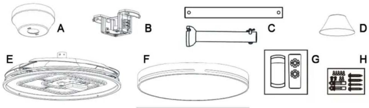
The product packaging should include the following components:
natural_image
Technical line drawings of various household appliances and fixtures (no text or symbols)A. Cup, B. Bracket, C. Long and short shaft, D. Cover, E. Appliance body, F. Ceiling light, G. Remote control, H. Wall plugs and hardware
If one or more parts are damaged or missing, contact your retailer to request replacement parts.
4. INSTALLATION AND FIRST START-UP
Unpack the appliance and check the integrity and completeness of the components, as specified in the previous chapter. Keep the packaging for 15 days in case it needs to be returned to the retailer; after this period, dispose of it in accordance with the recycling instructions indicated thereon. Carefully read this instruction booklet in its entirety, paying particular attention to the safety instructions, and carefully remove any materials used to secure the parts, including those inside the appliance.
Required tools:

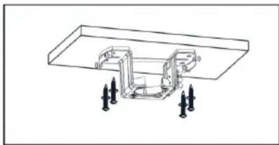
INSTALLATION IN WOOD CEILING:
natural_image
Technical line drawing of a mechanical assembly with mounting holes and mounting brackets (no text or symbols)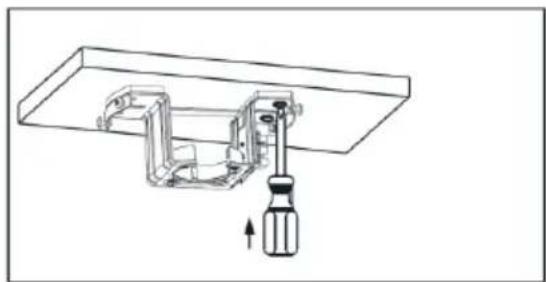
natural_image
Technical line drawing of a mechanical assembly with a screwdriver inserted, showing no text or symbolsPlace the bracket against the ceiling as shown in the figure, ensuring the surface is smooth and level. Perforate the surface with self-tapping screws and fully tighten them using a screwdriver with the corresponding head. After this procedure, carefully check that the holes are not stripped and that the material's density does not cause the screws to be pulled out once the appliance is installed.
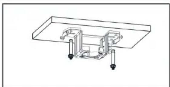
INSTALLATION IN MASONRY CEILING:
natural_image
Technical line drawing of a mechanical assembly with mounting flanges and housing (no text or symbols)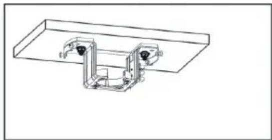
natural_image
Technical line drawing of a mechanical assembly with mounting brackets and housing (no text or symbols)Place the bracket against the ceiling as shown in the figure, ensuring the surface is smooth and level. Mark the points corresponding to the bracket holes, then drill the ceiling with an 8 mm bit suitable for M6 screws. Fully insert the wall plugs into the holes, then position the bracket again and fully tighten the screws.
Once the bracket is installed, always check, by applying manual force, that the fastening is sufficiently secure to prevent accidental detachment of the appliance over time. The bracket should remain immobile under a pull force of at least 60 kg. Additional safety measures for installation are outlined in Chapter 2.
natural_image
Technical line drawing of a mechanical device with arrows indicating motion or force (no text or symbols)POSITIONING THE APPLIANCE
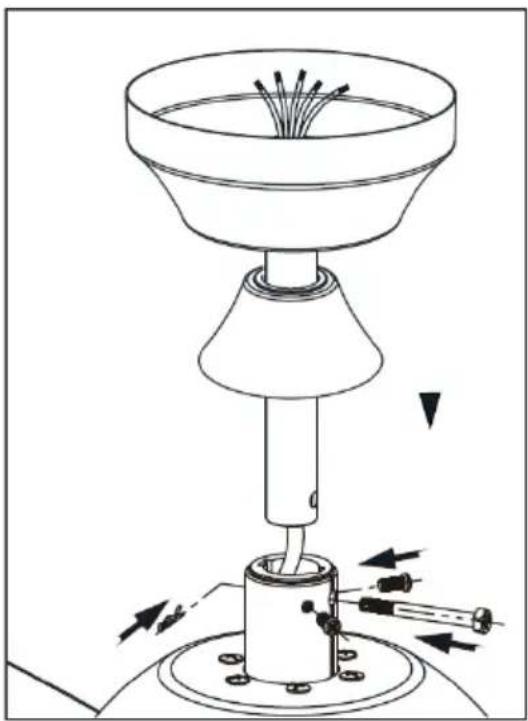
Remove the clip shown on the left in the image and extract the cross pin. Select the shaft length best suited to the ceiling height and pass the cable through it. Re-insert the cross pin, making sure the holes in the shaft align with those on the appliance, then re-insert the clip and tighten the screws to secure the shaft-appliance body connection in place.
natural_image
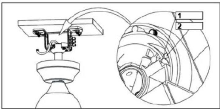
Technical line drawing of a mechanical assembly with two views (top and side), no visible text or symbolsHang the shaft-motor assembly in the hollow spherical groove of the bracket, then rotate the shaft until the notch on the bracket aligns with the slot along the sphere, as illustrated.
1=groove
2=notch
ELECTRICAL CONNECTIONS:
Connection diagram
text_image
Controller wiring Diagram AC-AIN-L AC-AIN-E AC-AIN-N Hanger bracket Terminal block Earth wire Input wire set of controller Remote Receiver Input wire set of light Input wire set of MotorThe wall switch can be used for general power control: once power has been supplied to the appliance, all its functions can be controlled via the supplied remote control. No additional wiring is required if the appliance is installed in place of a previously installed chandelier.
Before making the electrical connections, ensure the power is disconnected via the corresponding switch on the electrical panel.
Connect each plug to its corresponding socket, then connect the ground wire to terminal E, the neutral wire to terminal N, and the live wire to terminal L. Once the connections have been made, reactivate the switch on the electrical panel.
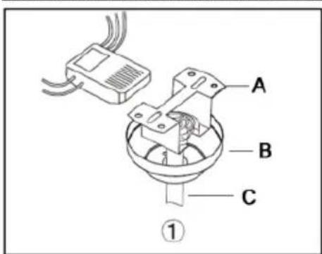
CORRECT POSITIONING OF THE CONTROL UNIT:
text_image
A B C ①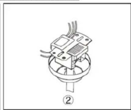
natural_image
Technical line drawing of a mechanical component with no visible text or symbols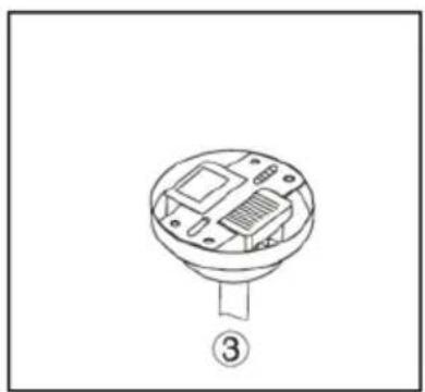
natural_image
Diagram of a circular electronic component with internal circuitry and labeled part (3), no text or symbols present.A = Bracket | B = Cup | C = Shaft
SECURING THE CUP:
text_image
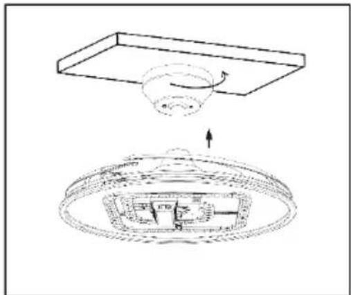
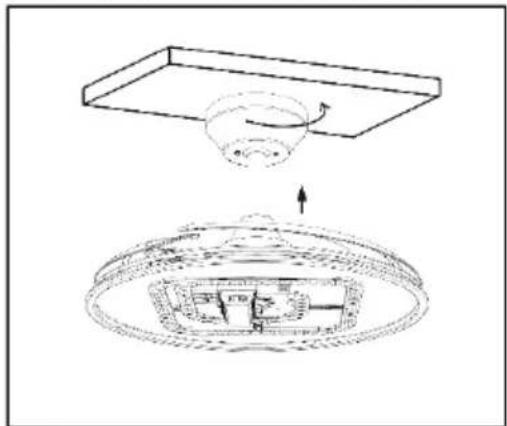
Technical diagram showing a ceiling structure with an arrow indicating rotation and a detailed interior layout below.Place the cup against the ceiling and rotate it slightly in the direction of the arrow shown in the figure, so that the holes align with the screw slots in the bracket. Insert the screws and tighten them securely.
INSTALLING THE CEILING LIGHT:

natural_image
Technical line drawing of a ceiling-mounted device with internal components and an upward arrow indicating motion (no text or symbols)Align the notches on the inner edge of the ceiling light with the grooves along the outer edge of the appliance. Push the ceiling light firmly upwards, then rotate it slightly clockwise until it is fully secured.
DYNAMIC BALANCING OF THE BLADES:
During operation, the appliance may produce
vibrations and sway, primarily due to improper assembly or, to a lesser extent, asymmetry of its components. In such cases, always check first and foremost for correct assembly, that the screws are properly tightened, that the parts are installed in the right direction and that there are no foreign bodies attached to the blades (e.g. pieces of adhesive tape, etc.). It may also be helpful to measure the distance from several points along the upper edge of the motor body, which should always be the same.
Only after ruling out issues caused by improper assembly can dynamic balancing of the blades be performed, as described below:
natural_image
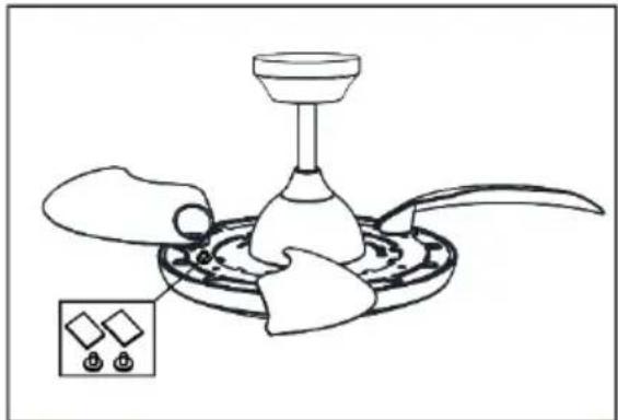
Line drawing of a mechanical device with a funnel and base, showing internal components (no text or symbols)1) Turn the fan on at the lowest speed and gradually increase it to determine at which speed the issue is most noticeable.
2) Stop the rotation and place a magnet to the side of the base of one of the blades, as shown in the figure. Restart the fan and observe whether the issue has lessened or worsened.
3) Perform successive tests by moving one or
more magnets along the edge of the blade until the position where the problem is least noticeable is identified.
4) Replace the magnets with one of the adhesive weights provided, attaching it in the same position. The weights can be cut into smaller pieces to urther refine the balance. 5) If necessary, repeat the same procedure near the other blades to determine the possibility of further refining the balance.
5. USING THE APPLIANCE
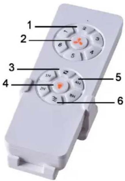
The appliance can only be controlled using the remote control. The commands are transmitted via radio, such that no specific orientation is required when pressing the buttons. The functions of each button are described below:
text_image
1 2 3 4 5 61) Rotation speed selector (1=slow, 6=fast)
2) Start/stop rotation button
3) Reverse rotation button
4) Light on/off button*
5) Delayed stop selector (1-8 hours)
6) Natural ventilation button
*The colour temperature changes with each activation, cycling through warm, natural and cool light, then back to warm, and so on. For the colour temperature to be the same the next time the light is turned on, it must remain on for at least 45 seconds.
Delayed stop:
Buttons (5) activate the automatic shutdown timer as soon as they are pressed. Note that pressing any other button will deactivate the timer, which will then need to be reset by pressing one of buttons (5) again. When the timer countdown is over (which is not visually indicated), the appliance will automatically stop fan rotation and turn off the light without any action being required on the user's part.
Natural ventilation:
This function involves a sequence of automatic speed variations to make the airflow uneven, mimicking natural outdoor breezes, which can prove beneficial to the health of people located within the appliance's direct operating range. Pressing the button activates the sequence, whereas pressing any speed selection button (1) stops the natural ventilation, reverting the airflow to a steady speed as selected.
6. CLEANING AND MAINTENANCE
The product requires no maintenance apart from the periodic replacement of the remote control batteries, which should always be removed during long periods of non-use. To replace the remote control batteries, slide the back cover outwards, then remove the batteries and dispose of them in compliance with current environmental protection regulations. Insert new batteries, ensuring the correct polarity, then reattach the back cover by sliding it back into place in the opposite direction.
For cleaning, disconnect the power supply from the switch on the electrical panel and wipe the surfaces with a damp cloth, avoiding aggressive or abrasive cleaning agents.
Wait for the appliance to fully dry before reconnecting the power supply at the electrical panel.
7. TROUBLESHOOTING
| Problem | Possible cause | Probable solution |
| Neither the fan nor the light turns on, but the LED on the remote control lights up when a button is pressed | A switch on the power line is in the open position | Flip the switch to the closed position |
| The mains power supply is interrupted | Check the electrical panel or wait for the power supply to be restored, notifying technical support if necessary | |
| Neither the fan nor the light turns on, nor does the LED on the remote control light up when a button is pressed | The remote control batteries are flat. | Replace the remote control batteries |
| Fan rotation causes swaying and/or vibrations | The blades are misaligned | Perform the dynamic balancing procedure as outlined in Chap. 4 |
Should any malfunctions other than those listed above occur, a self-sufficient solution is not feasible and the product must be inspected by a qualified technician.
8. TECHNICAL DATA
Power supply voltage : 220 - 240 V AC 50 Hz
Maximum power : 65 Watts
External dimensions (L x H x D) : maximum 102 x 46 x 102 cm
Weigh t: 6.5 Kg
9. PRODUCT COMPLIANCE
The producer Melchioni Spa declares that the product Ceiling stirrer with LED light Mod. MF2503CEI (cod. 118620074) is in compliance with Directive 2014/30/EU of the European Parliament and of the Council, of 26 february 2014, on the harmonisation of the laws of the Member States relating to electromagnetic compatibility.
The producer Melchioni Spa declares that the product Ceiling stirrer with LED light Mod. MF2503CEI (cod. 118620074) is in compliance with Directive 2014/35/EU of the European Parliament and of the Council, of 26 february 2014, on the harmonisation of the laws of the Member States relating to the making available on the market of electrical equipment designed for use within certain voltage limits.
The producer Melchioni Spa declares that the product Ceiling stirrer with LED light Mod. MF2503CEI (cod. 118620074) is in compliance with Directive 2009/125/EC of the European Parliament and of the Council, of 21 october 2009, establishing a framework for the setting of ecodesign requirements for energy-related products.
The producer Melchioni Spa declares that the product Ceiling stirrer with LED light Mod. MF2503CEI (cod. 118620074) is in compliance with Directive 2011/65/EU of the European Parliament and of the Council, of 8 June 2011 and subsequent Commission Delegated Directive 2015/863, on the restriction of the use of certain hazardous substances in electrical and electronic equipment.
According to Directive 2012/19/EU of the European Parliament and of the Council, of 4 July 2012, on waste electrical and electronic equipment (WEEE), the presence of the crossed-out bin symbol indicates that this appliance is not to be considered as urban waste: its disposal must therefore be carried out by separate
collection. Disposal in a non-separate manner may constitute a potential harm to the environment and health. This product can be returned to the distributor when purchasing a new device. Improper disposal of the appliance constitutes misconduct and is subject to sanctions by the Public Security Authority. For further information, contact the local administration responsible for environmental matters.
10. PRODUCT WARRANTY
Melchioni Spa, based in Milan (Italy), via Colletta 37, recognizes a conventional guarantee on the product for a period of two years from the date of the first purchase by the consumer. This guarantee does not affect the validity of the legislation in force concerning consumer goods (Legislative Decree 6 September 2005 n. 206 art. 128 and following), of which the consumer remains the owner. This guarantee applies to the entire territory of the European Union.
The components or parts that are found to be defective for ascertained manufacturing causes will be repaired or replaced free of charge through the dealer, during the above warranty period. Melchioni Spa reserves the right to make a complete replacement of the device, if repairability is impossible or excessively expensive, with another device of similar characteristics (Legislative Decree 6 September 2005 no. 206 art. 130) during the warranty period. In this case, the validity of the warranty remains that of the original purchase: the service provided under warranty does not extend the warranty period.
In any case, this appliance will not be considered defective in terms of materials or manufacture should it be adapted, changed or adjusted, in order to comply with national or local safety and / or technical standards, in force in a country other than that for which it is was originally designed and manufactured. This appliance has been designed and built for domestic use only: any other use will invalidate the benefits of the guarantee.
The warranty does not cover:
- parts subject to wear or tear, nor those parts that require periodic replacement and / or maintenance
• professional use of the product - malfunctions or any defects due to incorrect installation, configuration, software / BIOS / firmware update not performed by authorized Melchioni Spa
- repairs or interventions carried out by persons not authorized by Melchioni Spa
• manipulation of assembly components or, where applicable, of the software - defects caused by fall or transport, lightning, voltage fluctuations, liquid infiltration, opening of the appliance, bad weather, fire, public disturbances, inadequate ventilation or incorrect power supply
- any accessories, for example: boxes, bags, batteries, etc. used with this product
• home interventions for convenience checks or presumed defects
The recognition of the guarantee by Melchioni Spa is subject to the presentation of a tax document that proves the actual date of purchase. The same must not show any tampering or deletions, in the presence of which Melchioni Spa reserves the right to refuse the provision of treatment under warranty.
The warranty will not be recognized if the serial number or model of the appliance is non-existent, abraded or modified.
This warranty does not include any right to compensation for direct or indirect damage, of any nature, to people or things, caused by any inefficiency of the appliance. Any extensions, promises or services in this regard, insured by the retailer, will be borne by the latter.
1. NOTA INTRODUCTORIA
natural_image
Technical line drawings of household appliances and fixtures (no text or symbols)natural_image
Line drawings of five different tools: a rolled tube, wrench, screwdriver, pliers, and angle (no text or symbols)natural_image
Technical line drawing of a mechanical assembly with mounting holes and a central bracket (no text or symbols)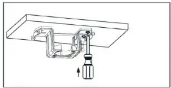
natural_image
Technical line drawing of a mechanical assembly with a screwdriver inserted into a housing (no text or symbols)natural_image
Technical line drawing of a mechanical assembly with mounting holes and internal components (no text or symbols)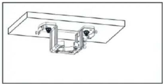
natural_image
Technical line drawing of a mechanical assembly with mounting brackets and housing (no text or symbols)natural_image
Diagram of a mechanical device with a funnel and base, showing directional arrows indicating movement or force (no text or symbols present)POSICIONAMIENTO DEL APARATO
natural_image
Technical line drawing of a mechanical assembly with labeled components (no text or symbols present)text_image
Controller wiring Diagram AC-AIN-L AC-AIN-E AC-AIN-N Hanger bracket Terminal block Earth wire Input wire set of controller Remote Receiver Input wire set of light Input wire set of MotorInput wire set of light = Conector de luz
Input wire set of motor = Conector de motor
Remote receiver = Unidad de controlCentralina
AC-A IN-L = Fase
natural_image
Technical line drawing of a mechanical component with no visible text or symbols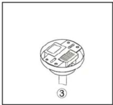
natural_image
Technical line drawing of a mechanical component with labeled part (3), no text or symbols presenttext_image
Technical diagram showing a mechanical assembly with labeled components and directional arrows indicating motion or flow.natural_image
Technical line drawing of a mechanical component with an upward arrow indicating motion (no text or symbols)natural_image
Line drawing of a mechanical device with a funnel and base, showing internal components (no text or symbols)natural_image
Technical line drawings of household appliances and fixtures (no text or symbols)natural_image
Line drawings of five different tools: a pipe fitting, wrench, screwdriver, pliers, and drafting lines (no text or symbols)natural_image
Technical line drawing of a mechanical assembly with mounting holes and mounting brackets (no text or symbols)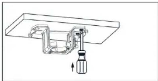
natural_image
Technical line drawing of a mechanical assembly with a screwdriver inserted into a housing (no text or symbols)natural_image
Technical line drawing of a mechanical assembly with mounting holes and internal components (no text or symbols)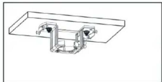
natural_image
Technical line drawing of a mechanical assembly with two components mounted on a flat base (no text or symbols)natural_image
Diagram of a mechanical device with a funnel and base, showing directional arrows indicating movement or force (no text or symbols present)POSITIONNEMENT DE L'APPAREIL
natural_image
Technical line drawing of a mechanical assembly with two labeled components (1 and 2), showing internal components and wiring (no text or symbols beyond labels)2=dent
text_image
AC-AIN-L AC-AIN-E AC-AIN-N Hanger bracket Terminal block Earth wire Input wire set of controller Remote Receiver Input wire set of light Input wire set of Motor Earth wireHanger bracket = Support de suspension
Terminal block = Bornier
natural_image
Technical line drawing of a mechanical component with no visible text or symbols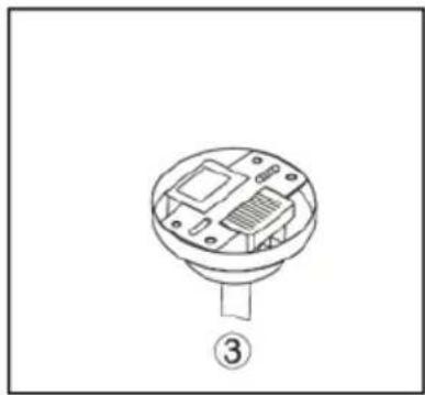
natural_image
Technical line drawing of a mechanical component with labeled part (3), no text or symbols presentA = support | B = Coupelle | C = Arbre
FIXATION DE LA COUPELLE :
text_image
Technical diagram showing a mechanical assembly with labeled components and directional arrows indicating motion or flow.natural_image
Technical line drawing of a ceiling-mounted device with internal components and an upward arrow indicating motion (no text or symbols)MONTAGE DU PLAFONNIER :
natural_image
Line drawing of a mechanical device with a funnel and base, showing internal components (no text or symbols)9. CONFORMITÉ DES PRODUITS
10. GARANTIE DU PRODUIT
natural_image
Technical line drawings of household appliances and fixtures (no text or symbols)natural_image
Line drawings of five different tools: a rolled tube, wrench, screwdriver, flat/plates, and pliers (no text or symbols)natural_image
Technical line drawing of a mechanical assembly with mounting holes and mounting brackets (no text or symbols)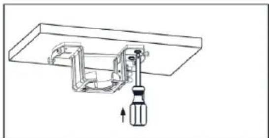
natural_image
Technical line drawing of a mechanical assembly with a screwdriver inserted into a housing (no text or symbols)natural_image
Technical line drawing of a mechanical assembly with mounting flanges and support posts (no text or symbols)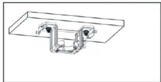
natural_image
Technical line drawing of a mechanical assembly with mounting brackets and housing (no text or symbols)natural_image
Technical line drawing of a mechanical device with arrows indicating motion or assembly (no text or symbols)natural_image
Technical line drawing of a mechanical assembly with labeled components (no text or symbols present)text_image
AC-AIN-L AC-AIN-E AC-AIN-N Hanger bracket Terminal block Earth wire Input wire set of controller Remote Receiver Input wire set of light Input wire set of Motor Earth wireTerminal block = Klemmenblock
Input wire set of motor = Motorstecker
Remote receiver = Steuereinheit
AC-A IN-L = Phase
AC-A IN-E = Erde
AC-A IN-N = Neutral
natural_image
Technical line drawing of a mechanical component with no visible text or symbols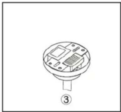
natural_image
Technical line drawing of a mechanical component with labeled part (3), no text or symbols presentA = Halterung | B = Becher | C = Welle