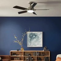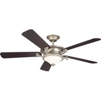
Rise - Fan Kichler - Free user manual and instructions
Find the device manual for free Rise Kichler in PDF.


| Product Type | Ceiling Fan |
| Brand | Kichler |
| Model | Rise |
| Blade Span | 60 inches (152.4 cm) |
| Net Weight | 10.70 kg |
| Gross Weight | 12 kg |
| Power Supply | 120 V, 60 Hz |
| Number of Blades | 5 |
| Motor Type | DC Motor (sensorless) |
| Reverse Function | Yes, for summer/winter airflow |
| Control | Wall control with dimmer |
| Light Kit Included | Yes, LED with glass shade |
| Light Dimmer | Integrated, compatible with wall control |
| Minimum Ceiling Height | 2.1 m (7 ft) from blades to floor |
| Maximum Ceiling Angle | 22° (requires downrod ≥ 12 in) |
| Maximum Outlet Box Weight | 15.9 kg (35 lb) |
| Certifications | cULus for fan support |
| Maintenance | Dry or slightly damp cloth; do not use water or detergents |
| Warranty | See Kichler website |
| Package Contents | Motor assembly, blades, light kit, wall control, receiver, mounting hardware |
Frequently Asked Questions - Rise Kichler
User questions about Rise Kichler
0 question about this device. Answer the ones you know or ask your own.
Ask a new question about this device
Download the instructions for your Fan in PDF format for free! Find your manual Rise - Kichler and take your electronic device back in hand. On this page are published all the documents necessary for the use of your device. Rise by Kichler.
USER MANUAL Rise Kichler
Product images may vary slightly from actual product.
natural_image
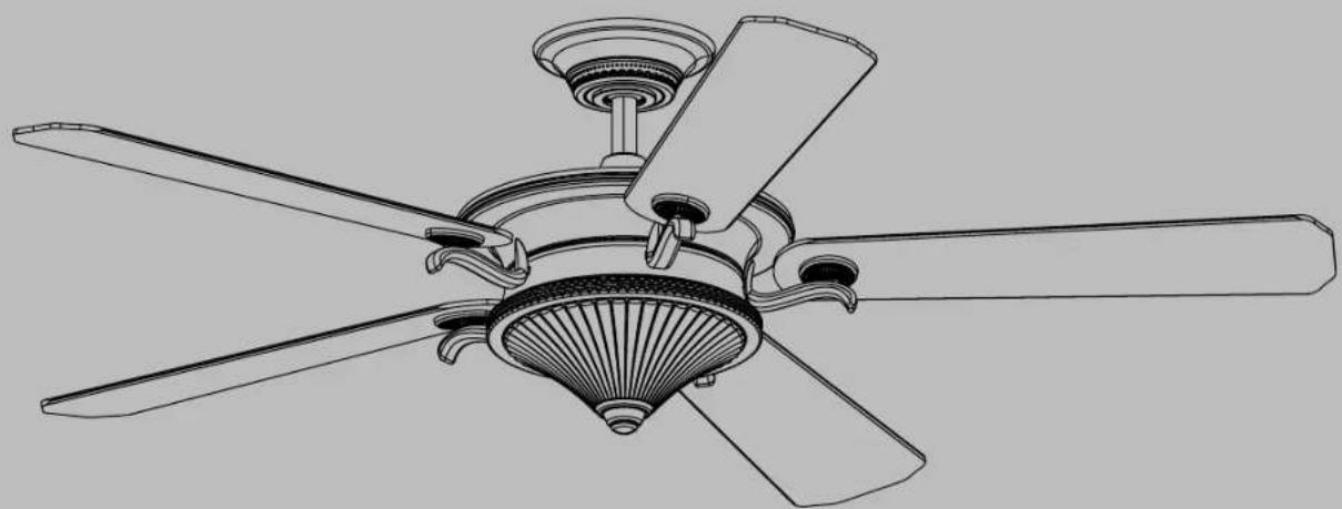
Line drawing of a five-blade ceiling fan with a decorative base (no text or symbols)INSTRUCTION MANUAL
Model# 300370READ
TABLE OF CONTENTS
SAFETY RULES....3
TOOLS REQUIRED....5
PACKAGE CONTENTS 5
MOUNTING OPTIONS ......6
HANGING THE MOTOR ASSEMBLY....7
INSTALLATION OF SAFETY SUPPORT......10
ELECTRICAL CONNECTIONS ......11
INSTALLING THE WALL CONTROL ....13
COMPLETING THE MOTOR INSTALLATION ....14
ATTACHING THE FAN BLADES 15
INSTALLING THE LIGHT PLATE ....16
INSTALLING THE LIGHT KIT AND GLASS SHADE .....17
SENSORLESS DC CONTROL PAIRING PROCEDURES ...18
OPERATING INSTRUCTIONS ....18
FCC INFORMATION 19
TROUBLESHOOTING 20
SAFETY RULES
READ AND SAVE THESE INSTRUCTIONS
WARNING: FOR CANADA, THIS FAN MUST BE SECURED DIRECTLY TO THE BUILDING STRUCTURE / CEILING JOIST. DON'T SECURE THIS FAN TO AN OUTLET BOX.
- CAUTION – RISK OF SHOCK – Disconnect Power at the main circuit breaker panel or main fusebox before starting and during the installation.
- WARNING: This fixture is intended for installation in accordance with the National Electrical Code (NEC) and all local code specifications. If you are not familiar with code requirements, installation by a certified electrician is recommended.
- WARNING: To reduce the risk of fire or electric shock, use only the control provided with the fan.
- WARNING: To reduce the risk of fire, electric shock, or Personal Injury mount to an outlet box marked "Acceptable For Fan Support of up to 15.9 kg (35 lbs)". For outlet box mounting, use mounting screws (and lock washers) provided with the outlet box. Most outlet boxes commonly used for the support of light fixtures are not acceptable for fan support and
may need to be replaced. Due to the complexity of the installation of this fan, a qualified licensed electrician is strongly recommended.
- All wiring must be in accordance with the National Electrical Code ANSI/NFPA 70 and local electrical codes. Electrical installation should be performed by a qualified licensed electrician.
- The outlet box and support structure must be securely mounted and capable of reliably supporting a minimum of 15.9 kg (35 pounds). Use only cULus Listed outlet boxes marked "FOR FAN SUPPORT".
- WARNING: TO REDUCE THE RISK OF FIRE, ELECTRIC SHOCK OR PERSONAL INJURY, MOUNT FAN TO OUTLET BOX MARKED "ACCEPTABLE FOR FAN SUPPORT".
- Avoid placing objects in the path of the blades.
SAFETY RULES
- To avoid personal injury or damage to the fan and other items, be cautious when working around or cleaning the fan.
- Make sure the installation site you choose allows a minimum clearance of 2.1 m (7 feet) from the blades to the floor and at least 30 inches from the ends of the blades to any obstruction.
- To operate the reverse function on this fan, press the reverse button while the fan is running.
- WARNING: make sure the power is disconnected before cleaning your fan.
- Do not use water or detergents when cleaning the fan or fan blades. A dry dust cloth or lightly dampened cloth will be suitable for most cleaning.
-
After making the electrical connections, spliced conductors should be turned upward and pushed carefully up into outlet box. The wires should be spread apart with the grounded conductor and the equipment-grounding conductor on one side of the outlet box and the ungrounded conductor on the other side of the outlet box.
-
Electrical diagrams are for reference only. Light kits that are not packed with the fan must be ETL Listed and marked suitable for use with the model fan you are installing. Switches must be ETL General Use Switches. Refer to the Instructions packaged with the light kits and switches for proper assembly.
- All set screws must be checked, and retightened where necessary, before installation.
- The subject fan 300370 weight information is as below: Net Weight : 10.7 kgs / 23.54 lbs; Gross Weight: 12 kgs / 26.4 lbs.
WARNING
TO REDUCE THE RISK OF PERSONAL INJURY, DO NOT BEND THE BLADE BRACKETS DURING ASSEMBLY OR AFTER INSTALLATION. DO NOT INSERT OBJECTS IN THE PATH OF THE BLADES.
TOOLS AND MATERIALS REQUIRED
• Phillips Screwdriver
- Blade Screwdriver
• 11 mm Wrench
- Step Ladder
- Wire Cutters
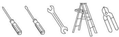
natural_image
Line drawings of five different tools: screwdriver, wrench, ladder, pliers, and flat screw (no text or symbols)PACKAGE CONTENTS
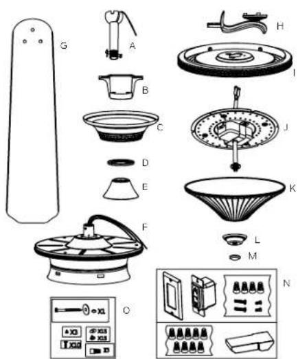
Unpack your fan and check the contents. You should have the following items:
A. Ball/Downrod Assembly
B. Mounting Bracket
C. Canopy
D. Canopy Hole Cover
E. Coupling Cover
F. Motor Assembly
G. Blade (5)
H. Bracket Assembly (5)
1. Light Plate
J. Light Kit
K. Glass Shade
L Finial Cap
M. Finial
N. Wall Control Unit
Face plate (1); Wall control (1); Receiver(1);
Wire Connector (4+9);
Short screw (2); Long screw (2);
O. Package hardware
1.) Safety cable hardware: Wood screw (1); Spring washer (1); Flat washer (1)
2.) Mounting hardware: Wire Connector (3);
3.) Blade attachment hardware: Screw (15); Washer (15)
4.) Light kit attachment hardware: Screw (3)
5.) Blade bracket attachment hardware: Screw (10)
text_image
Exploded view diagram of household appliances with labeled parts and control panelMOUNTING OPTIONS
If there is not an existing UL (cUL for Canadian Installation) listed mounting box, then read the following instructions. Disconnect the power by removing fuses or turning off circuit breakers.
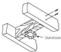
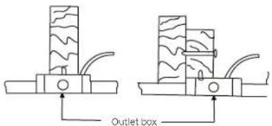
Secure the outlet box directly to the building structure. Use appropriate fasteners and building materials. The outlet box and its support must be able to fully support the full weight of the fan (up to 15.9kg (35 pounds)). Do not use plastic outlet boxes.
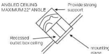
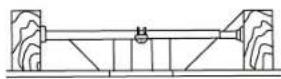
Figures 1, 2 and 3 are examples of different ways to mount the outlet box.
NOTE: If you are installing the ceiling fan on a sloped (vaulted) ceiling, you may need a longer downroot to maintain proper clearance between the tip of the blade and the ceiling. A minimum clearance of 12" is suggested for optimal operation.
NOTE: You must use 12" or longer downrod for 22° slope (max angle 22°). (Fig. 3)
NOTE: Depending on the location you have selected for installation, you may need to purchase and install a joist hanger for the support of the outlet box. Make sure the joist hanger you purchase has been designed for use with ceiling fans. (Fig. 4)
text_image
Outlet boxFig. 1
text_image
Outlet boxFig. 2
text_image
ANGLED CEILING MAXIMUM 22° ANGLE Provide strong support Recessed outlet box ceiling mounting planeFig. 3
Outlet box
Fig. 4
HANGING THE MOTOR ASSEMBLY
REMEMBER to turn off the power before you begin installation. This is necessary for your safety and also the proper programming of the control system.
To properly install your ceiling fan, follow the steps below.
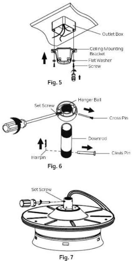
Step 1. Before attaching fan to outlet box (not included), ensure the outlet box is securely fastened to at least two points to a structural ceiling member (a loose box will cause the fan to wobble). Pass the 120 volt supply wires from the ceiling outlet box through the center of the ceiling mounting bracket. Install mounting bracket to outlet box in ceiling using the screws and washers included with the outlet box. (Fig. 5)
Step 2. Remove the hairpin and clevis pin from the downrod assembly, retain for later use. Remove the hanger ball from the downrod assembly by loosening set screw, removing the cross pin, and sliding ball of the rod. (Fig. 6)
NOTE: Make sure to keep loosened hardware separate to avoid confusion during installation.
Step 3. Loosen the two set screws on the motor coupling. (Fig. 7)
HANGING THE MOTOR ASSEMBLY (continued)
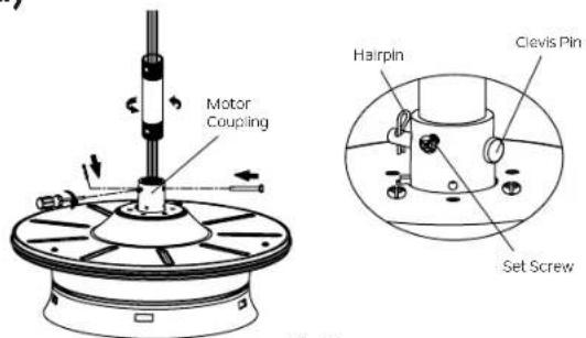
Step 4. Carefully feed fan wires and safety cable up through the downrod. Thread the downrod onto the motor coupling until the clevis pin holes are aligned. Next, replace the clevis pin and hairpin, then tighten both set screws. (Fig. 8)
Step 5. Slip the coupling cover, canopy hole cover and canopy onto the downrod. Carefully reinstall the hanger ball onto the downrod. Make sure the cross pin is in the correct position and the set screw is tight and the wires are not twisted. (Fig. 9)
CAUTION: Ensure all screws are tight before moving to the next step.
text_image
Motor Coupling Hairpin Clevis Pin Set ScrewFig. 8

text_image
Hanger Ball Canopy Canopy Hole Cover Coupling Cover Downrod Cross Pin Set ScrewFig. 9
HANGING THE MOTOR ASSEMBLY (continued)
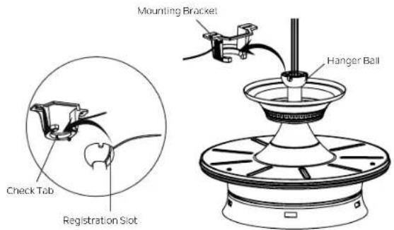
Step 6. Now lift the motor assembly into position and place the hanger ball into the mounting bracket. Rotate until the check tab has dropped into the registration slot and seats firmly. (Fig. 10) The entire motor body should not rotate if this is done correctly.
WARNING: Failure to properly seat the check tab can damage the ceiling fan during operation.
text_image
Mounting Bracket Check Tab Registration Slot Hanger BallFig. 10
INSTALLATION OF SAFETY SUPPORT (required for Canadian installation ONLY)
A safety support cable is provided to help prevent the ceiling fan from falling, please install it as follows.
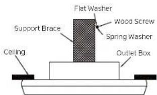
Step 1. Drive a wood screw and washers into the side of the brace that holds the outlet box. Leave 3mm (1/8") of space between the support brace and the washer. (Fig. 11)
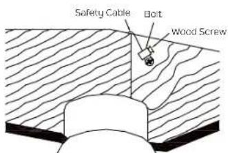
Step 2. Insert the safety cable through the mounting bracket and one of the holes in the outlet box into the ceiling. Adjust the length of the safety cable to reach the screw and washers by pulling the extra cable through the cable clamp until the overall length is correct, put the end of the cable back through the cable clamp, forming a loop at the end of the cable. Tighten the cable clamp securely. Now, put the loop in the end of the safety cable over the wood screw and under the washer. Tighten the wood screw securely. (Fig. 12)
NOTE: Although the safety support cable is required for Canadian installations only, it's a good idea to make the attachment with any installation.
text_image
Flat Washer Wood Screw Spring Washer Support Brace Ceiling Outlet BoxFig. 11
text_image
Safety Cable Bolt Wood ScrewFig. 12
ELECTRICAL CONNECTIONS
WARNING: To avoid possible electrical shock, be sure you have turned off the power at the main circuit panel before wiring.
Follow the steps below to connect the fan to your household wiring. Use the wire connectors supplied with your fan. Secure the connector with electrical tape. Make sure there are no loose wire stands or connections.
WARNING: If your house wires are different colors than referenced in this manual, stop immediately. A professional electrician is recommended to determine proper wiring.
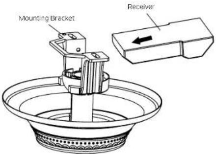
Step 1. Insert the receiver into the mounting bracket, and keep flat in opposition of ceiling. (Fig.13)
Step 2. Connect wires using the connectors as shown in WIRE DIAGRAM. (Fig.14)
WARNING: Check to see that all connections are tight, including ground, and that no bare wire is visible at the wire connections.
Step 3. After connections have been made, put the white and green leads (green or bare copper) to one side and the black leads towards the other side, the connection should be turned upward and carefully push leads into the outlet box. The wires should be spread apart with the grounded conductor and the equipment-grounding conductor on one side of the outlet box and the ungrounded conductor on the other side.
text_image
Mounting Bracket ReceiverFig. 13
WIRE DIAGRAM
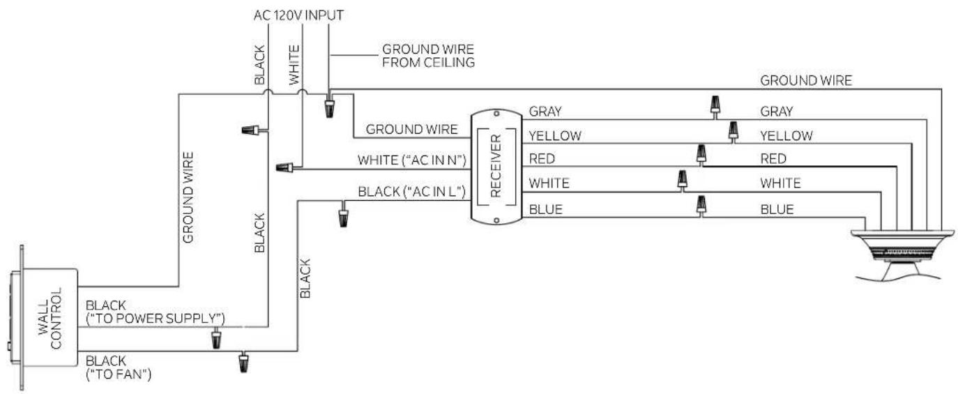
flowchart
graph TD
    A["Wall CONTROL"] -->|BLACK ("TO POWER SUPPLY")| B["Ground WIRE"]
    A -->|BLACK ("TO FAN")| C["Ground WIRE"]
    B --> D["AC 120V INPUT"]
    C --> E["WHITE"]
    D --> F["GROUND WIRE FROM CEILING"]
    E --> F
    F --> G["RECEIVER"]
    G --> H["GRAY"]
    G --> I["YELLOW"]
    G --> J["RED"]
    G --> K["WHITE"]
    G --> L["BLUE"]
    H --> M["GROUND WIRE"]
    I --> N["GREEN"]
    J --> O["RED"]
    K --> P["WHITE"]
    L --> Q["BLUE"]
    M --> R["GROUND WIRE"]
    N --> S["GROUND WIRE"]
    O --> T["GROUND WIRE"]
    P --> U["GROUND WIRE"]
    Q --> V["GROUND WIRE"]
Fig. 14
INSTALLING THE WALL CONTROL
WARNING: All wiring must be in accordance with the National Electrical Code and local electrical codes. Electrical installation should be performed by a qualified licensed electrician.
WARNING: SWITCH INSTALLATION MUST COMPLY WITH ALL LOCAL AND NATIONAL ELECTRIC CODES.
WARNING: Shut off main power at the circuit breaker or fuse panel before continuing.
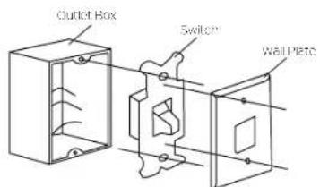
Step 1. Remove the existing wall plate and switch from the wall outlet box. Disconnect wires from existing switch. (Fig. 15)
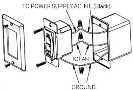
Step 2. Install the wall control to the outlet box, connecting the wires with wire connectors provided. (Fig. 16)
*Connect the black wire from the outlet box that supplies power to the wall control to black wire marked "TO POWER SUPPLY" from wall control.
*Connect the black wire from the outlet box that goes to the fan to black wire marked "TO FAN" from wall control.
*Connect the bare copper ground wire from the outlet box to bare copper ground wire from wall control.
*Connect the two white neutral wires in the outlet box together (if not already connected).
Step 3. Secure the wire connectors and make sure there are no loose strands or connections. Carefully tuck wire connections back inside outlet box and secure the wall control to outlet box with screws provided. Secure face plate to wall control using the screws provided.
text_image
Outlet Box Switch Wall PlateFig. 15
text_image
TO POWER SUPPLY AC IN L (Black) TO FAN GROUNDFig. 16
COMPLETING THE MOTOR INSTALLATION
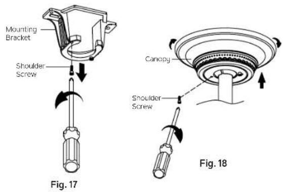
Step 1. Remove one of the two shoulder screws in the mounting bracket. Loosen the second shoulder screw without fully removing it. (Fig. 17)
Step 2. Assemble canopy by rotating key slot in canopy over shoulder screw in mounting bracket. Reinstall the shoulder screw that was previously removed, then retighten two shoulder screws securely. (Fig. 18)
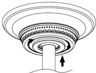
Step 3. Securely attach and tighten the canopy hole cover over the shoulder screws in the mounting bracket utilizing the keyslot twist-lock feature.(Fig.19)
natural_image
Diagram of a circular mechanical component with concentric rings and a central shaft, showing directional arrows (no text or symbols)Fig. 19
ATTACHING THE FAN BLADES
CAUTION: To Reduce The Risk Of Electric Shock, Disconnect The Electrical Supply Circuit To The Fan Before Installing Fan Blades.
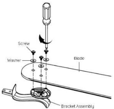
Step 1. Attach the blades to the bracket assemblies as shown, securely tighten with screws and washers from the hardware pack. (Fig. 20)
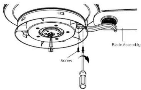
Step 2. Slide the blade assemblies into the holes on the flywheel and securely tighten the with the screws from the hardware pack as shown. (Fig.21)
text_image
Screw Washer Blade Bracket AssemblyFig. 20
text_image
Screw Blade AssemblyFig. 21
INSTALLING THE LIGHT PLATE
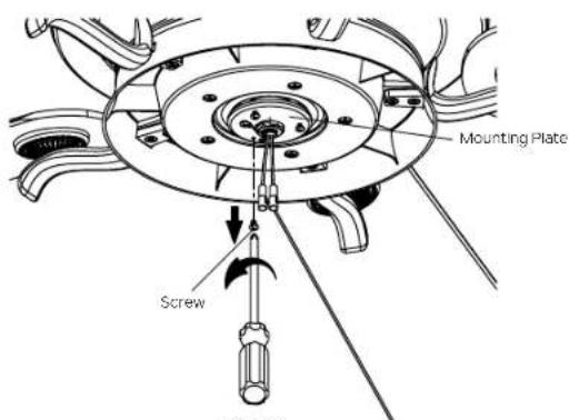
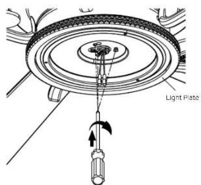
Step 1. Remove the screw marked with a brown dot label on the mounting plate and keep for later use. Loosen the other two (do not remove).(Fig.22)
Step 2. Place the two slot holes on the light plate over the 2 screws previously loosened from the mounting plate. Rotate the light plate until it locks in place at the narrow end of the key holes. Secure by tightening the 2 screws previously loosened and the one previously removed. (Fig. 23)
text_image
Mounting Plate Screw Fig. 4-1Fig. 22
text_image
Light PlateFig. 23
INSTALLING THE LIGHT KIT AND GLASS SHADE
CAUTION: To Reduce The Risk Of Electric Shock, Disconnect The Electrical Supply Circuit To The Fan Before Installing Light Kit.
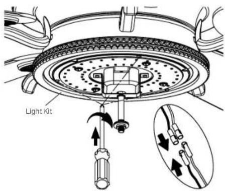
Step 1. Hold the LED light kit to light plate, then connect the 2 single pin connectors from the light kit to the 2 single pin connectors from the motor assembly. Connect the black wire to the black wire, and white wire to the white wire. Attach the light kit to the light plate and securely tighten with three (3) screws from the screw pack (Fig. 24)
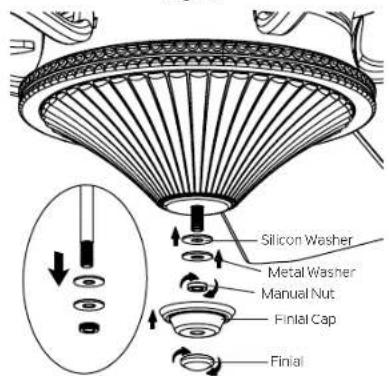
Step 2. Remove and retain the manual nut, metal washer and silicone washer from the threaded rod on the light kit. (Fig. 25)
Step 3. Lift the glass shade up to the light kit, allowing the threaded rod to go through the center hole in the bottom of the glass shade. Place the silicon washer and metal washer over the threaded rod, then screw the manual nut onto the threaded rod until tight. DO NOT OVER-TIGHTEN. (Fig. 25)
Step 4. Install the finial cap and finial onto the threaded rod and tighten securely. (Fig. 25)
text_image
Light KitFig. 24
text_image
Silicon Washer Metal Washer Manual Nut Finial Cap FinalFig. 25
SENSORLESS DC CONTROL PAIRING PROCEDURES
IMPORTANT: Ceiling fan blades MUST be installed before pairing procedure can begin.
Step 1. Press the power button "💡" to turn off the wall control (the button will be up). Restore electricity to the ceiling fan branch circuit at the circuit breaker or fuse box. Within 60 seconds of turning on the power, press the "💡" power button to turn on the wall control (the button will be down) and then press the "💡" reverse button for 3 to 5 seconds. The light will flash twice, and at the same time, the fan will run for a while and then stop. The remote will now be programmed to your fan and ready for use.
IMPORTANT: Do not press any buttons on the remote until after the pairing process is complete. Wait until after the fan has come to a complete stop.
Step 2. Try different speed settings on the wall control to ensure the fan is now fully functional. If programming is unsuccessful, retry the process starting from step 1 again.
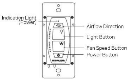
Press the power button "💡" once to turn ON (or OFF) the fan. (Fig. 26)
To set the desired fan speed, press and hold the "button to decrease and increase the speed. (Fig. 26)
To turn the light on and off, press and release the light " 🔊" button. To set the light intensity, press and hold the light button. The light will turn on at the light intensity previously selected. (Fig. 26)
text_image
Indication Light (Power) Airflow Direction Light Button Fan Speed Button Power ButtonFig.26
REVERSE FUNCTION
To operate the reverse function on this fan, press the "reverse button while fan is running. Speed setting for warm or cool weather depends on factors such as the room size, ceiling height, number of fans and so on."
Warm Weather Operation: Forward (counter clockwise). A downward airflow creates a cooling effect (Fig.27). This allows you to set your air conditioner on a warmer setting without affecting your general comfort.
Cool Weather Operation: Reverse (clockwise). An upward airflow moves warm air off of the ceiling (Fig. 28). This allows you to set your heating unit on a cooler setting without affecting your general comfort.
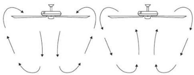
flowchart
graph TD
    A["Top Vessel"] --> B["Left Vessel"]
    B --> C["Right Vessel"]
    C --> D["Bottom Vessel"]
    D --> E["Left Vessel"]
    E --> F["Right Vessel"]
    F --> G["Bottom Vessel"]
    G --> H["Left Vessel"]
    H --> I["Right Vessel"]
    I --> J["Bottom Vessel"]
    J --> K["Left Vessel"]
    K --> L["Right Vessel"]
    L --> M["Bottom Vessel"]
    M --> N["Left Vessel"]
    N --> O["Right Vessel"]
    O --> P["Bottom Vessel"]
    P --> Q["Left Vessel"]
    Q --> R["Right Vessel"]
    R --> S["Bottom Vessel"]
    S --> T["Left Vessel"]
    T --> U["Right Vessel"]
    U --> V["Bottom Vessel"]
Fig. 27 Fig. 28
FCC Information
This device complies with part 15 of the FCC Rules. Operation is subject to the following two conditions:
1.) This device may not cause harmful interference, and
2.) This device must accept any interference received, including interference that may cause undesired operation.
Note: This equipment has been tested and found to comply with the limits for a Class B digital device, pursuant to part 15 of the FCC Rules. These limits are designed to provide reasonable protection against harmful interference in a residential installation. This equipment generates, uses and can radiate radio frequency energy and, if not installed and used in accordance with the instructions, may cause harmful interference to radio communications. However, there is no guarantee that interference will not occur in a particular installation. If this equipment does cause harmful interference to radio or television reception, which can be determined by turning the equipment off and on, the user is encouraged to try to correct the interference by one or more of the following measures:
• Reorient or relocate the receiving antenna.
- Increase the separation between the equipment and receiver.
- Connect the equipment into an outlet on a circuit different from that to which the receiver is connected.
- Consult the dealer or an experienced radio/TV technician or help.
TROUBLESHOOTING
ProblemProblem SolutionSolution
Fan will not start. Fan will not start circuit fuses or breakers.1. Check circuit fuses or breakers.
- Check all electrical connections to ensure proper contact.
CAUTION: Make sure the main power is OFF when checking any electrical connection.
Fan sounds noisy. Fan so. Makes sure all motor housing screws are snug.
-
Make sure the screws that attach the fan blade brackets to the motor are tight.
-
Make sure wire nut connections are not rubbing against each other or the interior wall of the switch housing.
CAUTION: Make sure main power is off. CAUTION: Make sure main power is off.
-
Allow a 24-hour "breaking-in" period. Most noise associated with a new fan disappears during this time.
-
If using an optional light kit, make sure the screws securing the glassware are tight. Make sure the light bulbs are not touching any other component.
-
Do not connect this fan to a wall mounted variable speed control(s). They are not compatible with ceiling fan motors or remote controls.
-
Make sure the upper canopy has a short distance from the ceiling. It should not touch the ceiling.
Fan wobble.Fan wobble1. Check that all blade and blade arm screws are secure.
-
Most fan wobbling problems are caused when blade levels are unequal. Check this level by selecting a point on the ceiling above the tip of one of the blades. Measure this distance. Rotate the fan until the next blade is positioned for measurement. Repeat for each blade. The distance deviation should be equal within 1/8".
-
If the blade wobble is still noticeable, interchanging two adjacent (side by side) blades can redistribute the weight and possibly result in smoother operation.
Remote control Remot4.CeilingFans with remote control systems CAN NOT be operated in conjunction with any other control system EXCEPT a malfunction.malfunctionbasic On/off wall switch, if desired.
KICHLER®
www.kichler.com
KICHLER LIGHTING LLC
7711 EAST PLEASANT VALLEY ROAD
CLEVELAND, OHIO 44131
CUSTOMER SERVICE 866.558.5706
8:00 AM TO 5:00 PM EST, MONDAY - FRIDAY
REV. 04-MAR-2022
© Kichler Lighting LLC. All Rights Reserved.
KICHLER®
Rise 152,40 cm (60 po)
natural_image
Line drawing of a five-blade ceiling fan with a decorative base (no text or symbols)LISEZ ET CONSERVEZ CES INSTRUCTIONS
MANUEL D'INSTRUCTIONS
Modèle n° 300370
TABLE DES MATIÈRES
RÈGLES DE SÉCURITÉ ....3
OUTILS NÉCESSAIRES....5
CONTENU DU COLIS ....5
OPTIONS DE MONTAGE 6
SUSPENDRE L'ENSEMBLE MOTEUR ....7
INSTALLATION DU SUPPORT DE SÉCURITÉ....10
CONNEXIONS ÉLECTRIQUES ......11
INSTALLATION DE LA COMMANDE
MURALE 13
TERMINER L'INSTALLATION DU MOTEUR ....14
FIXATION DES PALES DU VENTILATEUR .....15
INSTALLATION DE LA PLAQUE D'ÉCLAIRAGE ......6
INSTALLATION DU KIT D'ÉCLAIRAGE ET DU VERRE ... 17
PROCÉDURES D'APPARIEMENT DE LA
COMMANDE CC SANS CAPTEUR ....18
MODE D'EMPLOI ....18
INFORMATIONS CFC 19
DÉPANNAGE 20
RÈGLES DE SÉCURITÉ
LISEZ ET CONSERVEZ CES INSTRUCTIONS
AVERTISSEMENT : POUR LE CANADA, CE VENTILATEUR DOIT ÊTRE FIXÉ DIRECTEMENT À LA STRUCTURE DU BÂTIMENT OU À LA SOLIVE DE PLAFOND. NE PAS FIXER CE VENTILATEUR À UNE BOÎTE DE SORTIE.
natural_image
Line drawings of five different tools: screwdriver, wrench, ladder, pliers, and flat screw (no text or symbols)CONTENU DU COLIS
H. Ensemble de support (5)
text_image
Exploded diagram of household appliances and fixtures with labeled parts and control panelOPTIONS DE MONTAGE
natural_image
Diagram of concentric circular layers with arrows indicating direction, labeled Fig. 19 (no text or symbols on the diagram itself)FIXATION DES PALES DU VENTILATEUR
CLEVELAND, OHIO 44131
SERVICE À LA CLIENTÈLE 866.558.5706
natural_image
Line drawing of a five-blade ceiling fan with a decorative base (no text or symbols)natural_image
Line drawings of five different types of screwdrivers and pliers, no text or symbols presenttext_image
Exploded view diagram of household appliances with labeled parts and control panelOPCIONES DE MONTAJE
natural_image
Diagram of a circular mechanical component with concentric rings and directional arrows indicating motion (no text or symbols)Figura 19
CLEVELAND, OHIO 44131
SERVICIO AL CLIENTE 866.558.5706
8:00 AM A 5:00 PM EST, DE LUNES A VIERNES
REV. 04-MAR-2022