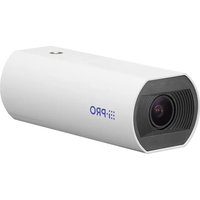
WV-U11350-V3 - Surveillance Camera i-PRO - Free user manual and instructions
Find the device manual for free WV-U11350-V3 i-PRO in PDF.


| Product Type | Indoor AI Network Camera with Varifocal Lens |
| Brand | i-PRO |
| Model | WV-U11350-V3 |
| Resolution | 2 Megapixels (AI Model) |
| Dimensions (L x H x D) | 59 mm x 49 mm x 142 mm |
| Weight | Approx. 290 g |
| Power Supply | PoE (IEEE 802.3af), 48 V DC, 140 mA / 6.7 W |
| Operating Temperature | -10 °C to +50 °C |
| Operating Humidity | 10 % to 90 % (non-condensing) |
| Housing Material | PC resin, i-PRO white |
| Main Functions | Built-in AI, varifocal lens, built-in microphone, microSD card (up to 512 GB), audio output, LINK/ACT indicators, motorized zoom |
| Network Connectivity | RJ45 10BASE-T/100BASE-TX |
| Installation | Ceiling or wall, requires mounting bracket WV-QCL102-W (optional), M6 screws (4x) |
| Security | Included security cable, fixing screws with minimum tensile strength 562 N, professional installation recommended |
| Maintenance and Cleaning | Disconnect power before maintenance; periodic inspections to verify fastening and rust |
| Spare Parts and Repairability | Optional accessories available (see i-PRO website); included security cable and washers |
| General Information | Indoor use only, professional use, not intended for children |
Frequently Asked Questions - WV-U11350-V3 i-PRO
User questions about WV-U11350-V3 i-PRO
0 question about this device. Answer the ones you know or ask your own.
Ask a new question about this device
Download the instructions for your Surveillance Camera in PDF format for free! Find your manual WV-U11350-V3 - i-PRO and take your electronic device back in hand. On this page are published all the documents necessary for the use of your device. WV-U11350-V3 by i-PRO.
USER MANUAL WV-U11350-V3 i-PRO
Included Installation Instructions
Network Camera
For professional use only
Indoor use
| Model No. | WV-U11550-V3 |
| WV-U11350-V3 | |
| WV-U11501-V3 | |
| WV-U11301-V3 | |
| WV-U11301-F3 |
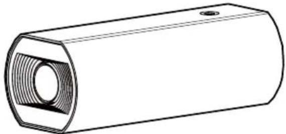
natural_image
Technical line drawing of a cylindrical mechanical part with a recessed hexagonal opening and internal threading (no text or symbols)WV-U11550-V3
About the user manuals
Product documentation is composed of the following documents.
- Installation Guide (this document): Provides information about "Precautions", "Precautions for installation" and the installation method.
- Web Guide (Refer to the link on the following product information website): Includes installation videos, basic functions, and basic operation methods for this device.
- User manual (Refer to the link on the following product information website): This section describes the software operating instructions common to each model. https://i-pro.com/products_and_solutions/en/surveillance/documentation-database
"
(https://i-pro.com/products_and_solutions/en/surveillance/learning-and-support/knowledge-base/technical-information) and will guide you to the right information.
- Before attempting to connect or operate this product, please read these instructions carefully and save Important Safety Instructions leaflet for future use.
- microSDXC/ microSDHC/ microSD memory card is described as microSD memory card.
- The external appearance and other parts shown in this manual may differ from the actual product within the scope that will not interfere with normal use due to improvement of the product.
i-PRO Co., Ltd.
Tokyo, Japan
https://www.i-pro.com/
Authorised Representative in EU: i-PRO EMEA B.V.
Laarderhoogtweg 25, 1101 EB Amsterdam, Netherlands
i-PRO EMEA B.V. UK Branch 1010 Cambourne Business Park, Cambridgeshire CB23 6DP


About notations and model number explanation
U11550 : WV-U11550-V3 (5MP AI vari-focal model)
U11350 : WV-U11350-V3 (2MP AI vari-focal model)
U11501 : WV-U11501-V3 (5MP Non-AI vari-focal model)
U11301 : WV-U11301-V3 (2MP Non-AI vari-focal model)
U11301F : WV-U11301-F3 (2MP Non-AI fixed focus model)
Trademarks and registered trademarks
- SD, microSD and microSDXC Logos are trademarks of SD-3C, LLC.
- All other trademarks identified herein are the property of their respective owners.
Disposal of Old Equipment and Batteries
Only for European Union and countries with recycling systems
These symbols on the products, packaging, and/or accompanying documents mean that used electrical and electronic products and batteries must not be mixed with general household waste. For proper treatment, recovery and recycling of old products and used batteries, please take them to applicable collection points in accordance with your national legislation.
By disposing of them correctly, you will help to save valuable resources and prevent any potential negative effects on human health and the environment.
For more information about collection and recycling, please contact your local authority.
Penalties may be applicable for incorrect disposal of this waste, in accordance with national legislation.

Note for the battery symbol (bottom symbol)
This symbol might be used in combination with a chemical symbol. In this case it complies with the requirement set by the Directive for the chemical involved.
For U.S.A.
NOTE: This equipment has been tested and found to comply with the limits for a Class A digital device, pursuant to Part 15 of the FCC Rules. These limits are designed to provide reasonable protection against harmful interference when the equipment is operated in a commercial environment. This equipment generates, uses, and can radiate radio frequency energy and, if not installed and used in accordance with the instruction manual, may cause harmful interference to radio communications.
Operation of this equipment in a residential area is likely to cause harmful interference in which case the user will be required to correct the interference at his own expense.
FCC CAUTION: Changes or modifications not expressly approved by the party responsible for compliance could void the user's authority to operate the equipment.
Supplier's Declaration of conformity
Trade name : i-PRO
Model No.: WV-U11550-V3, WV-U11501-V3
WV-U11350-V3, WV-U11301-V3
WV-U11301-F3

Responsible Party :
i-PRO Americas Inc.
8550 Fallbrook Drive, Suite 200 Houston,
Texas 77064
Support Contact: 1-800-513-5417
For U.S.A.
The model number and serial number of this product may be found on the surface of the unit.
You should note the model number and serial number of this unit in the space provided and retain this book as a permanent record of your purchase to aid identification in the event of theft.
Model No. ____
Serial No. ____
For U.S.A.
This device complies with part 15 of the FCC Rules.
Operation is subject to the following two conditions: (1) This device may not cause harmful interference, and (2) this device must accept any interference received, including interference that may cause undesired operation.
For Canada
CAN ICES-3(A)/NMB-3(A)
- Operation of this product in a residential environment could cause radio interference.
Caution: Notice:
- The DC power supply connected to the camera must be in the same building.
- The network camera is only intended for a connection to an ethernet or PoE network without routing to the outside plant.
- This product has no power switch. Be sure to install disconnect devices such as a circuit breaker to shut down the main power of power supplying equipment to this product.
-
Before attempting to connect or operate this product, please read these instructions carefully.
-
This product is not suitable for use in locations where children are likely to be present.
- Do not install this product in locations where ordinary persons can easily reach.
- This product is a professional equipment.
- For information about screws and other parts required for installation, refer to the corresponding section of this document.

: Direct current symbol
Precautions
In order to prevent harm to people and damage to property, it explains what must be observed without fail. The safety statements common to all i-PRO network camera models are posted on the website linked from the two dimensional barcode on the right. Please be sure to confirm it.
https://i-pro.com/products_and_solutions/en/surveillance/learning-and-support/knowledge-base/safety-instructions
■ Do not install this product in a restricted or prohibited environment.
Failure to observe this may result in injury, accident, or malfunction due to falling.
Please check the safety precautions common to all models on the website above and the installation precautions in the Installation Guide.
■ Refer installation work to the dealer.
Installation work requires technique and experience. Failure to observe this may cause fire, electric shock, injury, or damage to the product. Be sure to consult the dealer.
■ Install the product accurately and securely on an installation area in accordance with the installation instructions.
Failure to observe this may cause injury or accidents.
■ Take measures of protection against this product falling.
Failure to observe this may cause a drop resulting in injury.
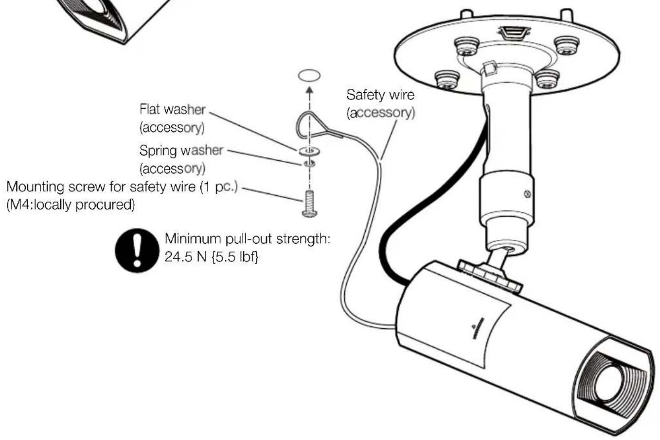
Securely fix the product to the installation surface using screws or anchors. If the fall prevention wire is included, be sure to install it.
■ Stop the operation immediately when something is wrong with this product.
When smoke goes up from the product, the smell of smoke comes from the product, or the exterior of the product has deteriorated, continued use will cause a fire or fall of the product resulting in injury, or damage to property.
In this case, turn the power off immediately and contact qualified service personnel for service.
■ Conduct periodic inspections.
Rust on the metal parts or screws may cause a fall of the product resulting in injury or accidents.
Consult the dealer for the inspections.
Be sure to turn off the power before inspection or maintenance.
Precautions for installation
i-PRO Co., Ltd. assumes no responsibility for injuries or property damage resulting from failures arising out of improper installation or operation inconsistent with this documentation.
In order to prevent injury, the product must be securely mounted to an installation surface according to Installation Guide.
■ Installation area for this product
Select an appropriate place for the installation area (such as a strong installation surface) in your particular environment.
- Make sure that the installation area is strong enough to hold this product, such as a concrete ceiling.
• Install the camera in the foundation area of the architecture or where sufficient strength is assured. - Do not mount the product on a plaster board or a wooden section because they are too weak. If the product is unavoidably mounted on such a section, the section shall be sufficiently reinforced.
■ This camera is designed to be used indoors
This product is not operable outdoors. Do not expose this camera to direct sunlight for hours and do not install the product near a heater or an air conditioner. Otherwise, it may cause deformation, discoloration and malfunction. Keep this camera away from water and moisture.
■ Do not place this product in the following places
- Locations where a chemical agent is used such as a swimming pool
- Locations subject to moisture or oil smoke such as a kitchen
- Locations that have a specific environment that is subject to an inflammable atmosphere or solvents
- Locations where a radiation, an X-ray, a strong radio wave or a strong magnetic field is generated
- Locations near coasts directly subjected to sea breezes, or locations subject to corrosive gases such as from hot springs, volcanic regions, etc.
- Locations where the temperature is not within the specified range
- Locations subject to vibrations, such as on vehicles, marine vessels, or above product lines (This product is not designed for on-vehicle use.)
- Locations near rubber products containing sulfur (packing, rubber feet, etc.)
- Locations where it may get directly wet from rain or water splash (including under the eaves, etc.)
- Locations subject to moisture or dust
- Locations subject to sudden changes in temperature such as near air discharge vents of air conditioners or air circulation inlet doors
■ Screw tightening
Do not use an impact driver. Use of an impact driver may damage the screws or cause tightening excessively.
■ About reflection of light from outside or IR light
A ghost may appear on the screen depending on the incident angle of external light.
- Refer to our technical information website
■ Take notice of humidity
Install this product when the humidity is low. If installation is performed when it is raining or in very humid conditions, the inside may be affected by humidity, causing mist-over inside the lens.
■ Protection from lightning
When cables are used outdoors, there is a chance that they may be affected by lightning. In such a case, install a lightning arrestor close to the camera, and make the length of the network cable between the camera and lightning arrestor as short as possible to prevent the camera from being affected by lightning. Refer to our technical information website
■ When noise disturbance may happen
Noise may appear in video or audio near a strong electric field from a TV or radio antenna, motors and transformers, or a strong electric field/magnetic field from a power line (lamp line) of AC100 V or more. Conduct the power distribution work to keep 1 m {3.28 feet} away from them or conduct the electric conduit work using metal pipes. (Be sure to make ground connection of the metal pipes.)
■ Equipment classification and power source indication label
Refer to the indication label on the top side of this unit for the equipment classification, power source, and other information.
■ About static electricity
Before installing or removing this product, be sure to touch metal objects to discharge static electricity from your body.
| Specifications | |
| Power source *1: PoE (IEEE802.3af | compliant) |
| Power consumption *1: PoE 48 V DC: 140 mA / Approx. 6.7 W (Class 0 device) | |
| Operating environmentAmbient operating temperature: Ambient operating humidity: | -10 °C to +50 °C {14 °F to 122 °F}10 % to 90 % (no condensation) |
| Storage environmentStorage temperature: Storage humidity: | -30 °C to +60 °C {-22 °F to +140 °F}10 % to 95 % (no condensation) |
| Built-in microphone: Nondirectional U11501 U11301 U11301F | electret condenser microphone |
| Dimensions: 59 mm (W) × 49 mm | (H) × 142 mm (D){2-5/16 inches (W) × 1-15/16 inches (H) × 5-19/32 inches (D)}(excluding projection parts) |
| Mass: Approx. 290 g {0.64 lbs} | U11550U11350U11501U11301Approx. 250 g {0.55 lbs} U11301F |
| Finish: PC resin, i-PRO white | |
*1 Refer to our technical information website
Standard accessories
Important Safety Instructions .... 1 pc.
| Safety wire ×1 Spring washer ×1 Flat washer ×1 |
Other items that are needed (not included)
- Mounting screws
| Installation method | Recommended screw*1 | Minimum pull-out strength*2 |
| When mounting with WV-QCL102-WMount bracket: Approx. 240 g {0.53 lbs}Camera: Approx. 290 g {0.64 lbs} | M6 × 16 mm*3{5/8 inches} x 4 pcs. | 562 N {126 lbf} |
| Screw required to secure the safety wire | M4 × 16 mm*3{5/8 inches} x 1 pc. | 24.5 N {5.5 lbf} |
*1 Select screws according to the material of the location that the camera will be mounted to. In this case, wood screws and nails should not be used.
*2 This value indicates the minimum pull-out strength required value per screw. For information about the minimum pull-out strength, refer to our technical information website
*3 The screw length is an example when installing the camera on a robust installation surface with a thickness of 20 mm {25/32 inches} or more.
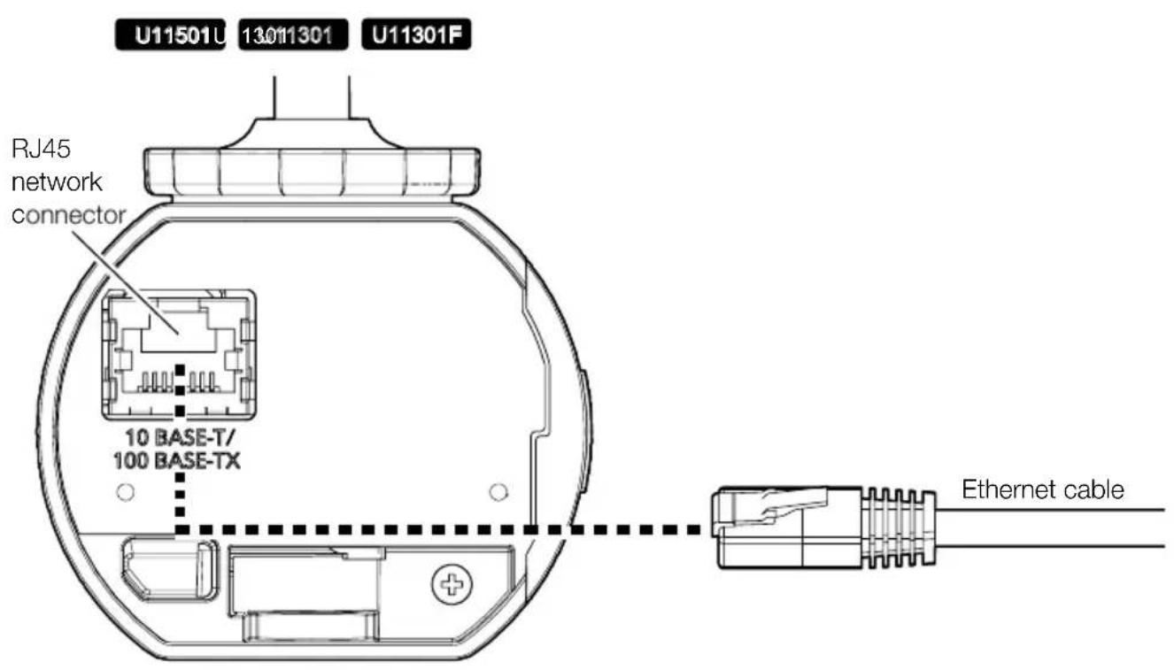
Ethernet cable with RJ45 plug (category 5e or better, straight, all 4 pairs (8 pins), less than 100m {328 feet})
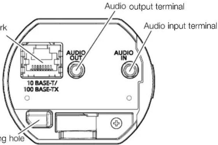
A necessary, audio input cable, audio output cable U11550 U11350
Hexagonal wrench (3 mm {1/8 inches})
Optional accessories

The latest information → Technical information website "Accessory Selector"
Troubleshooting
Before requesting service, refer to "Troubleshooting" of Web Guide. Then, confirm the trouble.
Installation Procedure
Technical Support Video
Parts and functions
U11550U
13501350
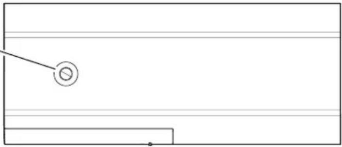
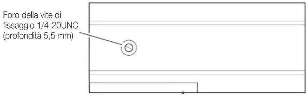
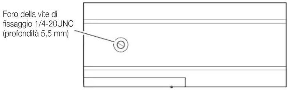
1/4-20UNC
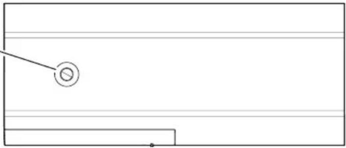
fixing screw hole
(depth 5.5 mm
{7/32 inches})
natural_image
Pure geometric diagram with horizontal lines and a circle, no text or symbols present
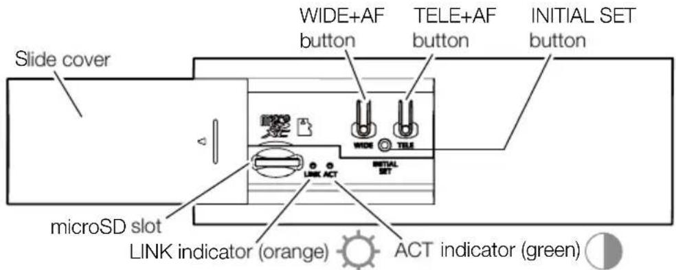
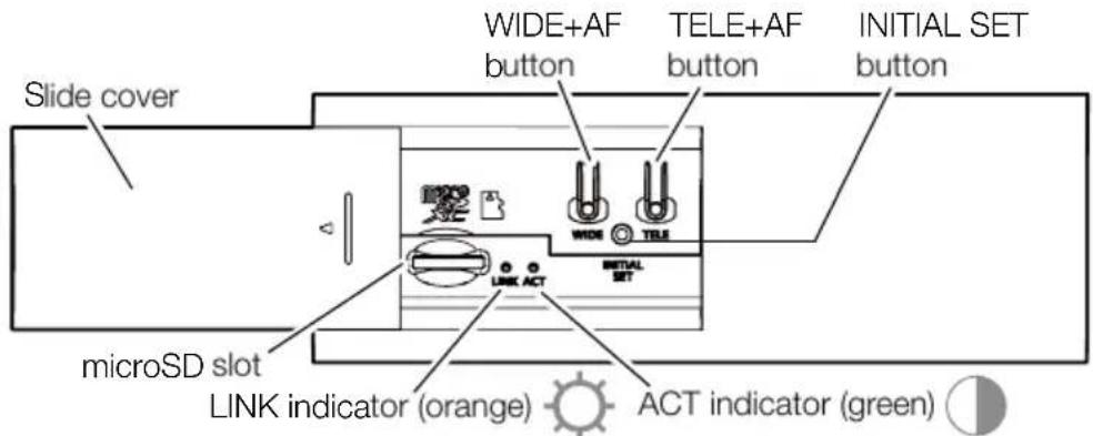
- All LEDs turn off ⇒User manual [Indicator]

: Lights

: Blinks

: Lights off
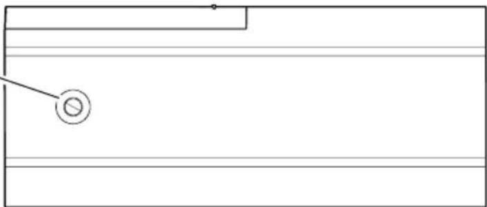
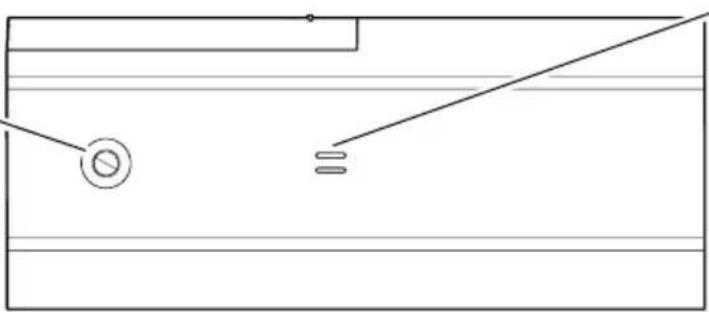
1/4-20UNC fixing screw hole (depth 5.5 mm {7/32 inches})
natural_image
Pure electrical circuit lines without any symbols
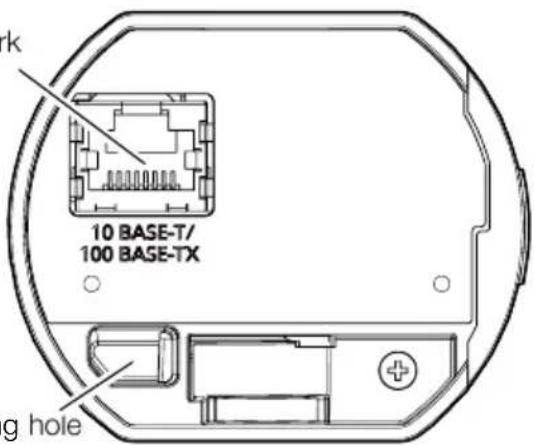
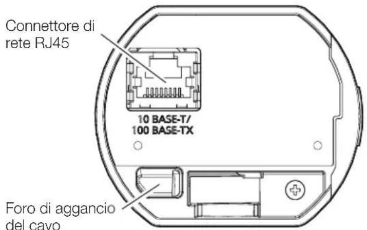
RJ45 network connector
Installation Procedure
Technical Support Video
Parts and functions
U11501U
13011301
1/4-20UNC
fixing screw hole
(depth 5.5 mm
{7/32 inches})
natural_image
Pure geometric diagram with horizontal lines and a circle, no text or symbols present
- All LEDs turn off ⇒User manual [Indicator]

: Lights

: Blinks

: Lights off
1/4-20UNC fixing screw hole (depth 5.5 mm {7/32 inches})
natural_image
Pure electrical circuit lines without any symbolsBuilt-in microphone hole
RJ45 network connector
Wire engaging hole
Installation Procedure
Technical Support Video
Parts and functions
U11301F
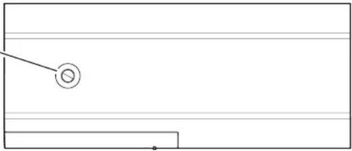
1/4-20UNC
fixing screw hole
(depth 5.5 mm
{7/32 inches})
natural_image
Pure technical line drawing of a rectangular block with a circular hole and a small protrusion (no text or symbols)
- All LEDs turn off ⇒User manual [Indicator]

: Lights

: Blinks

: Lights off
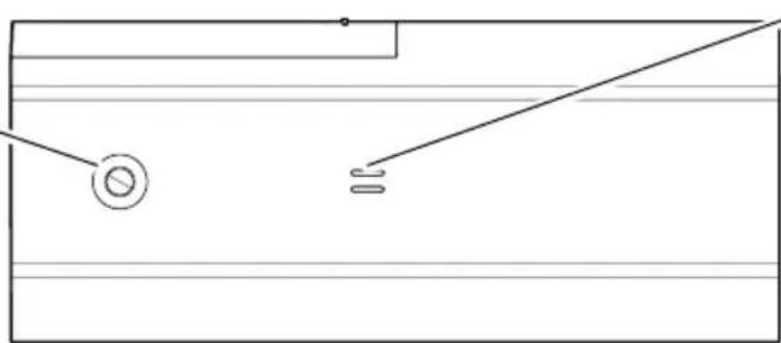
1/4-20UNC
fixing screw hole
(depth 5.5 mm
{7/32 inches})
natural_image
Pure electrical circuit lines without any symbolsBuilt-in microphone hole
RJ45 network connector
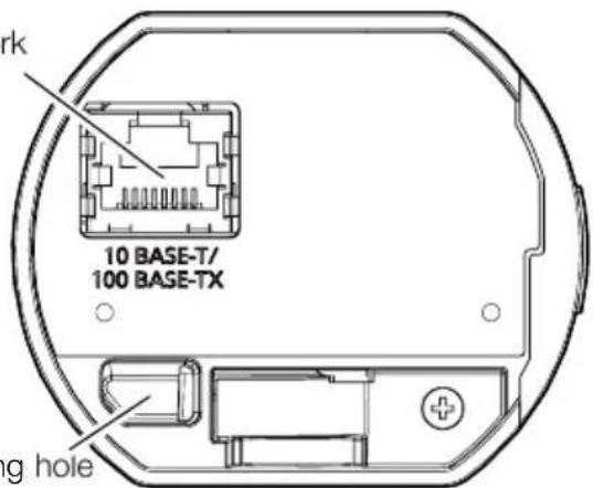
Wire engaging hole
Installation method
For installing on a wall
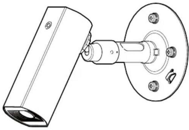
natural_image
Technical line drawing of a mechanical assembly with a cylindrical component and flanged housing (no text or symbols)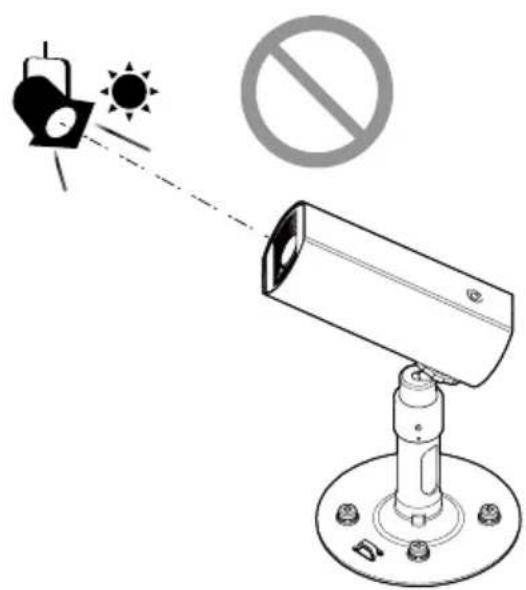
For installing on a ceiling
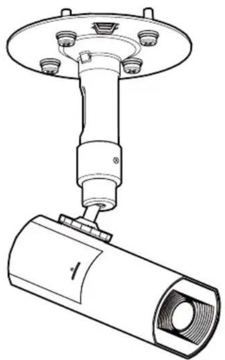
natural_image
Technical line drawing of a mechanical assembly with a cylindrical component and flanged top (no text or symbols)
Example of explanation for installation
For stationary
installation
natural_image
Technical line drawing of a mechanical device with a cylindrical component and mounting base (no text or symbols)
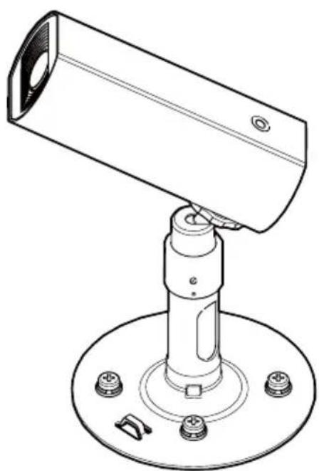
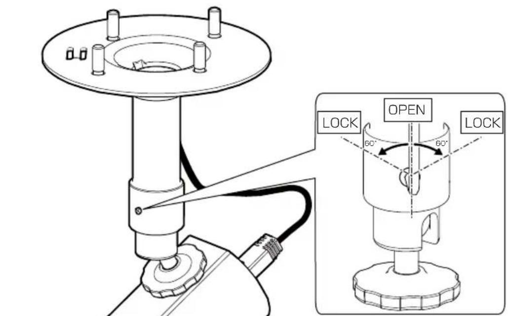
- This manual explains how to install this product on the ceiling using WV-QCL102-W (Universal camera mounting bracket).
Refer to our technical information website
Step 1 Preparations
*The following illustrations use the WV-U11550-V3 as an example.
■ Attach the safety wire (accessory).

Step 1 Preparations (Continued)
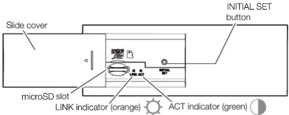
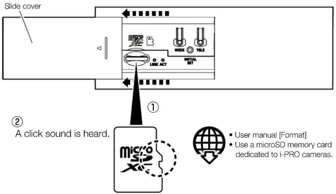
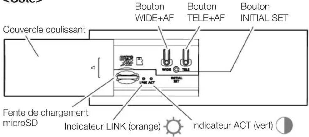
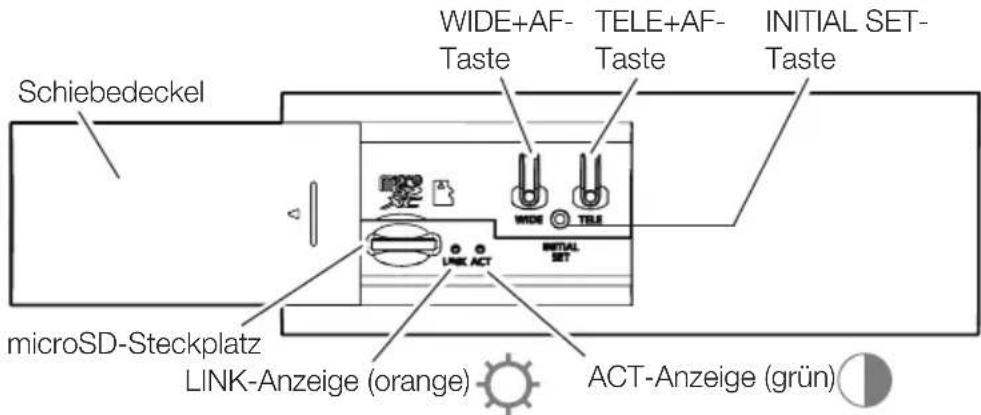
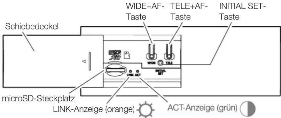
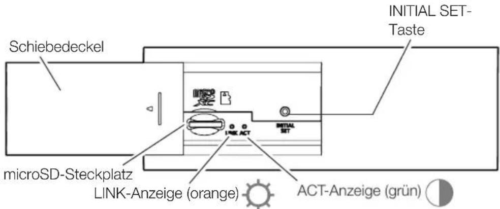
If necessary, insert a microSD memory card.
flowchart
graph TD
    A["Slide cover"] --> B["MicroSD Device"]
    B --> C["Link ACT"]
    C --> D["INITIAL SET"]
    D --> E["WIDE"]
    E --> F["TELE"]
    style A fill:#f9f,stroke:#333
    style B fill:#ccf,stroke:#333
    style C fill:#cfc,stroke:#333
    style D fill:#fcc,stroke:#333
    style E fill:#ffc,stroke:#333
    note right of B: A click sound is heard.
    note right of B: User_manual["Format"]
    note right of B: Use a microSD memory card dedicated to i-PRO cameras.
Step 2
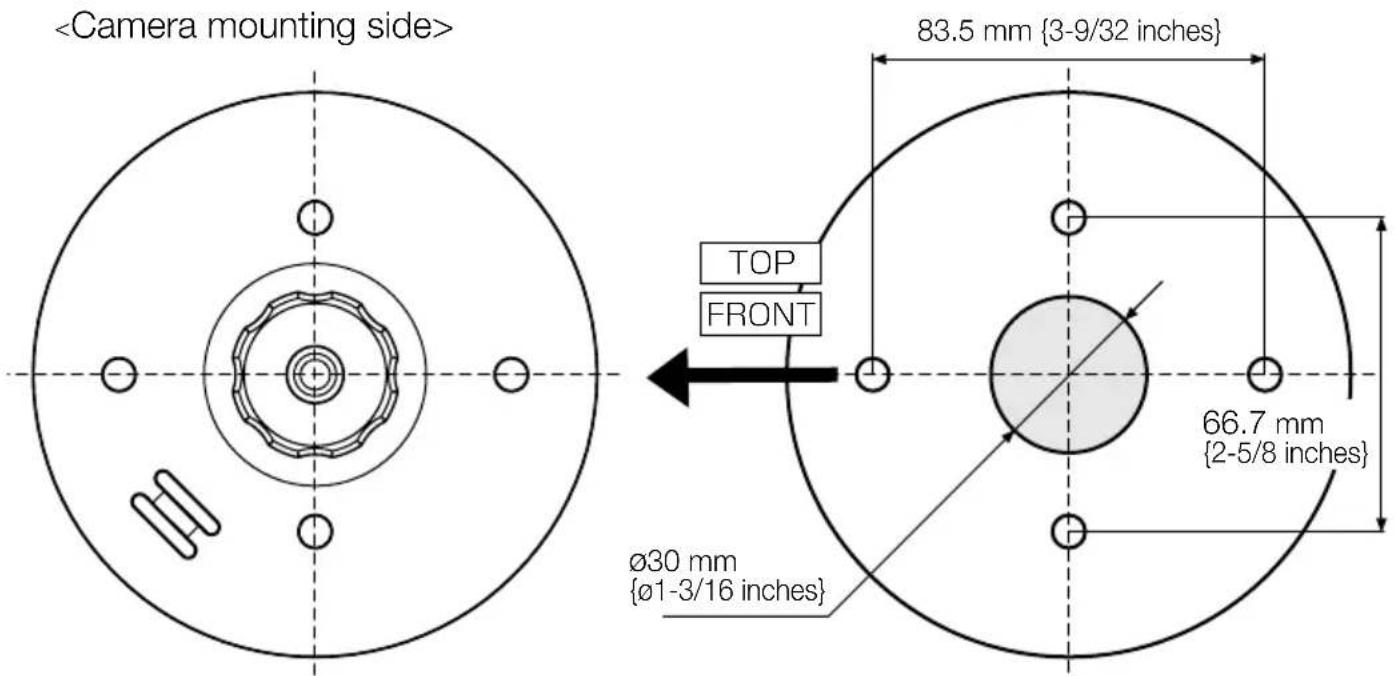
*Drill a hole in the center for wiring if necessary.
Step 3
■When wiring from above the ceiling
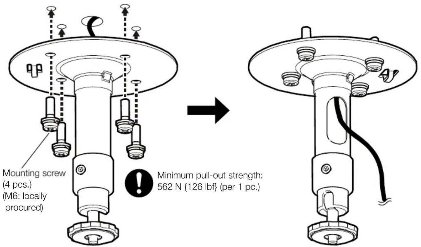

- Determine the mounting height of the camera so that the lowest part of the camera or the camera mounting bracket after the installation is 2 m 80 cm {110 inches} or higher from the floor.
Step 4
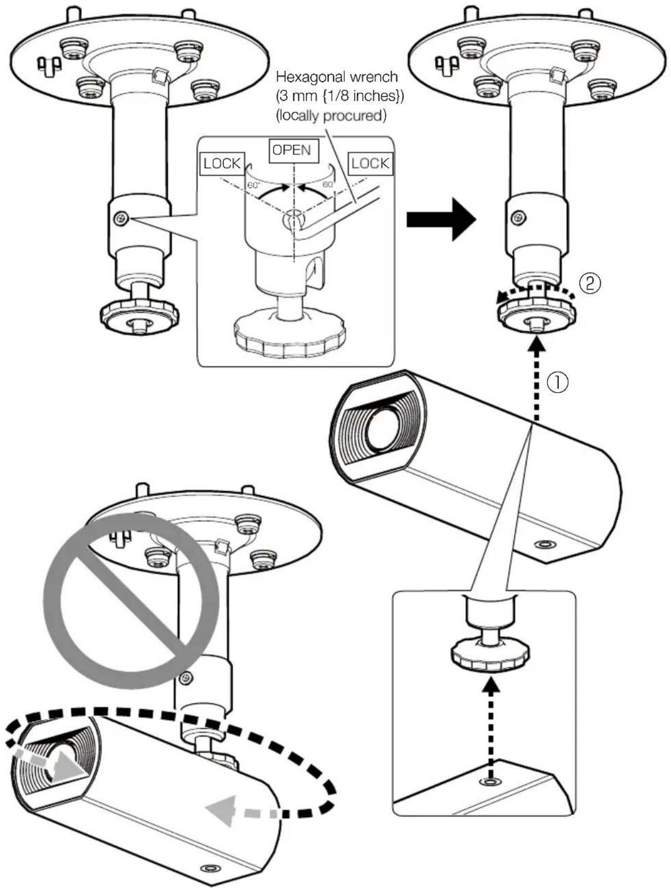
Step 5
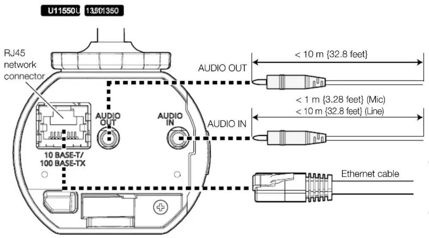
Step 6
→ Turn the power on (PoE).
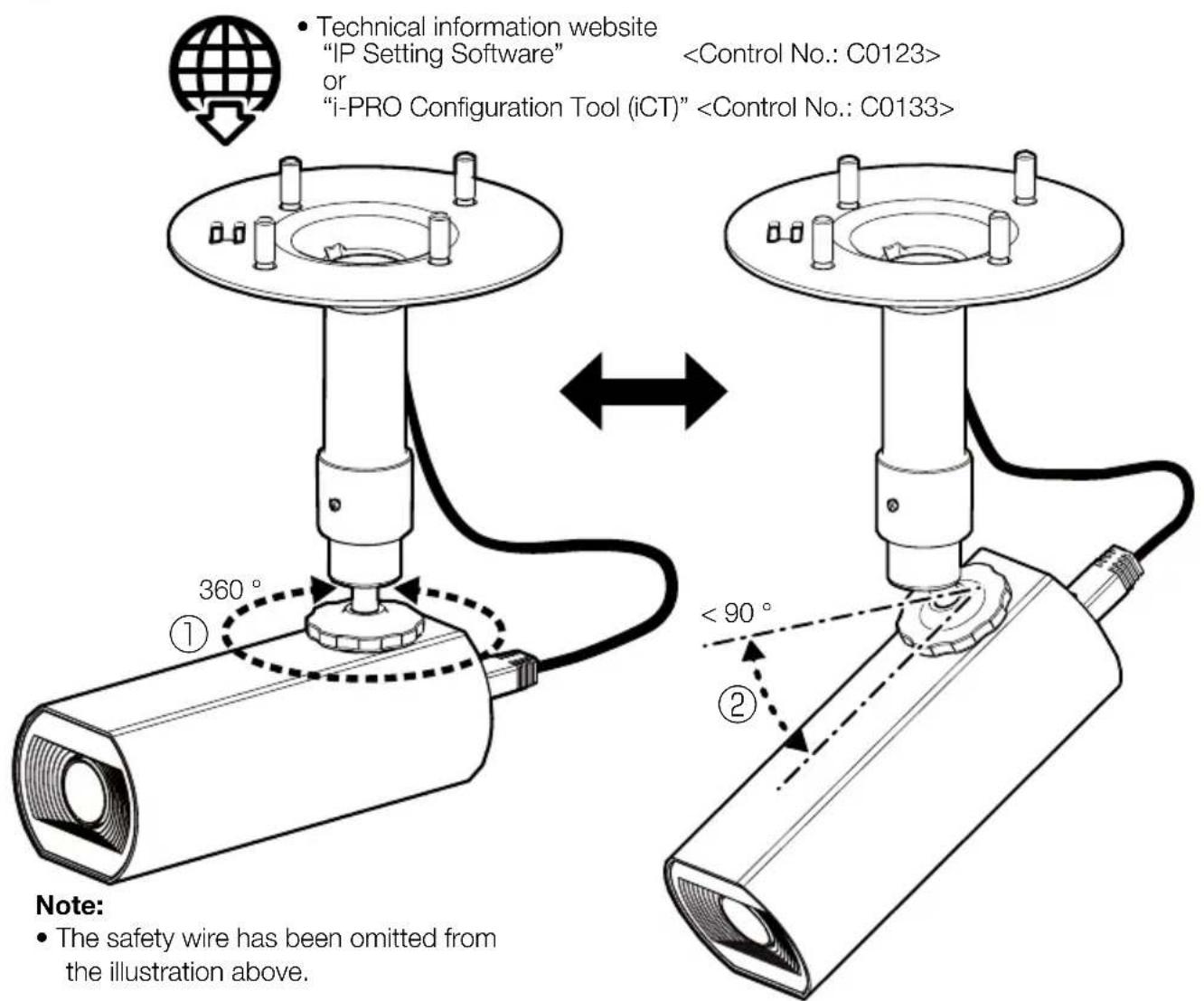
Step 7

Recommended tightening torque:
1.97 N·m {1.45 lbf·ft}
(Max. 2.95 N·m {2.17 lbf·ft})
natural_image
Technical line drawing of a hollow cylindrical mechanical part with a recessed inner cavity (no text or symbols)WV-U11550-V3
i-PRO Co., Ltd.
Tokyo, Japan
https://www.i-pro.com/
Authorised Representative in EU: i-PRO EMEA B.V.
Laarderhoogtweg 25, 1101 EB Amsterdam, Netherlands
i-PRO EMEA B.V. UK Branch 1010 Cambourne Business Park, Cambridgeshire CB23 6DP
CE
UK CA
8550 Fallbrook Drive, Suite 200 Houston,
Texas 77064
Contact support: 1-800-513-5417
Pour U.S.A.
Attention: Remarque:
https://i-pro.com/products_and_solutions/en/surveillance/learning-and-support/knowledge-base/safety-instructions

Technical Support Video
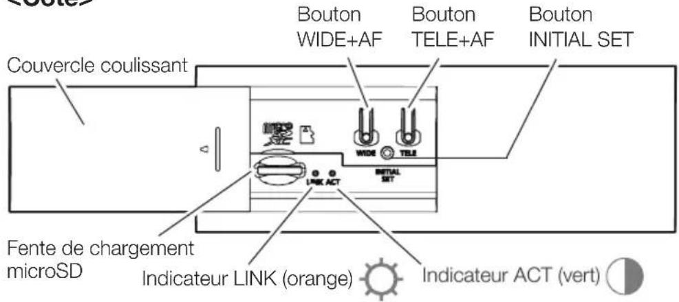
Pièces et fonctions
U11550U
13501350
natural_image
Pure geometric diagram with horizontal lines and a circle, no text or symbols present
natural_image
Pure technical diagram with horizontal lines and a circular symbol, no text or labels presentTechnical Support Video
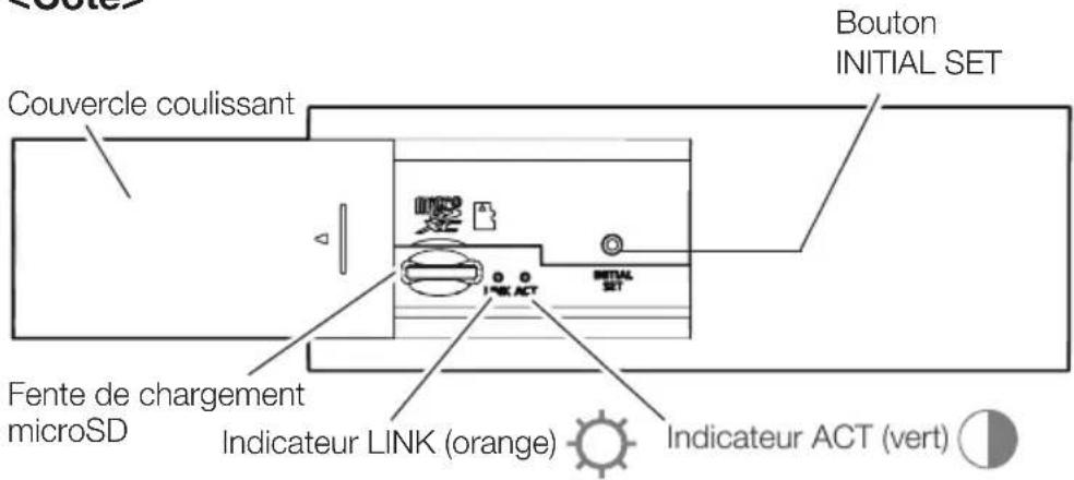
Pièces et fonctions
U11501
U11301
natural_image
Pure geometric diagram with horizontal lines and a small circle, no text or symbols present
natural_image
Pure electrical circuit lines without any symbolsTrou de microphone incorporé
Technical Support Video
Pièces et fonctions
U11301F
natural_image
Pure geometric diagram with horizontal lines and a small circle, no text or symbols present
natural_image
Pure electrical circuit lines without any symbolsTrou de microphone incorporé
natural_image
Technical line drawing of a mechanical assembly with a cylindrical component and flanged housing (no text or symbols)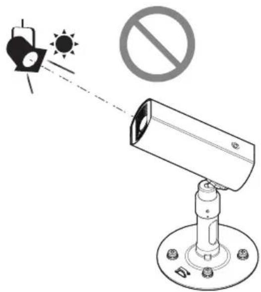
natural_image
Technical diagram of a mechanical assembly with a cylindrical component and a base, showing a downward arrow (no text or symbols present)natural_image
Technical line drawing of a mechanical device with a cylindrical component and mounting base (no text or symbols)Installationshandbuch
natural_image
Technical line drawing of a hollow cylindrical mechanical part with a recessed inner cavity (no text or symbols)WV-U11550-V3
Bedienerhandbücher
https://www.i-pro.com/
Authorised Representative in EU: i-PRO EMEA B.V.
Laarderhoogtweg 25, 1101 EB Amsterdam, Netherlands
i-PRO EMEA B.V. UK Branch 1010 Cambourne Business Park, Cambridgeshire CB23 6DP

https://i-pro.com/products_and_solutions/en/surveillance/learning-and-support/knowledge-base/safety-instructions
Important Safety Instructions .... 1 St.
Technical Support Video
natural_image
Pure geometric diagram with horizontal lines and a small circle, no text or symbols present
Technical Support Video
natural_image
Pure geometric diagram with horizontal lines and a circle, no text or symbols present
natural_image
Pure electrical circuit lines without any symbolsTechnical Support Video
natural_image
Pure geometric diagram with horizontal lines and a circle, no text or symbols present
natural_image
Pure electrical circuit lines without any symbolsnatural_image
Technical line drawing of a mechanical assembly with a cylindrical component and flanged housing (no text or symbols)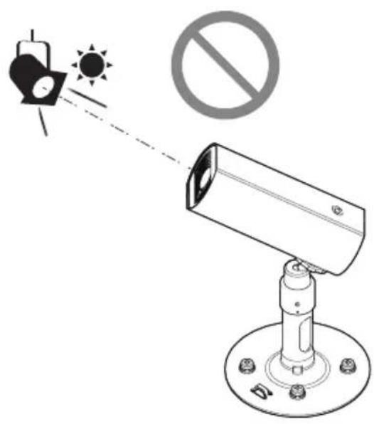
natural_image
Technical line drawing of a mechanical assembly with a cylindrical component and mounting flange (no text or symbols)natural_image
Technical line drawing of a mechanical device with a cylindrical component and mounting base (no text or symbols)natural_image
Technical line drawing of a hollow cylindrical mechanical part with a recessed inner cavity (no text or symbols)WV-U11550-V3
https://www.i-pro.com/
Authorised Representative in EU: i-PRO EMEA B.V.
Laarderhoogtweg 25, 1101 EB Amsterdam, Netherlands
i-PRO EMEA B.V. UK Branch 1010 Cambourne Business Park, Cambridgeshire CB23 6DP

https://i-pro.com/products_and_solutions/en/surveillance/learning-and-support/knowledge-base/safety-instructions
Technical Support Video
Parti e funzioni
U11550U
13501350
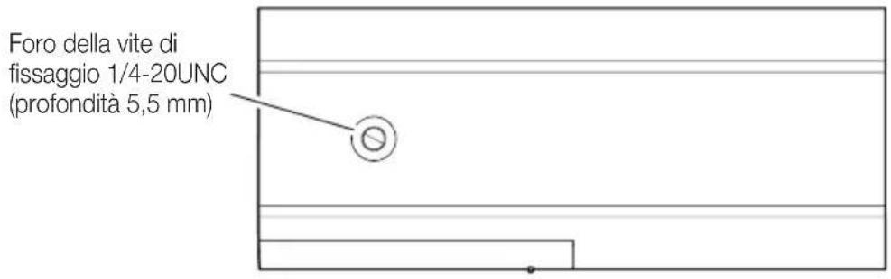
Technical Support Video
Parti e funzioni
U11501U
13011301
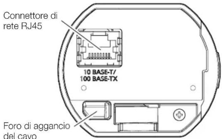
Built-in microphone hole
Technical Support Video
Parti e funzioni
U11301F
Built-in microphone hole
natural_image
Technical line drawing of a mechanical assembly with a cylindrical component and flanged housing (no text or symbols)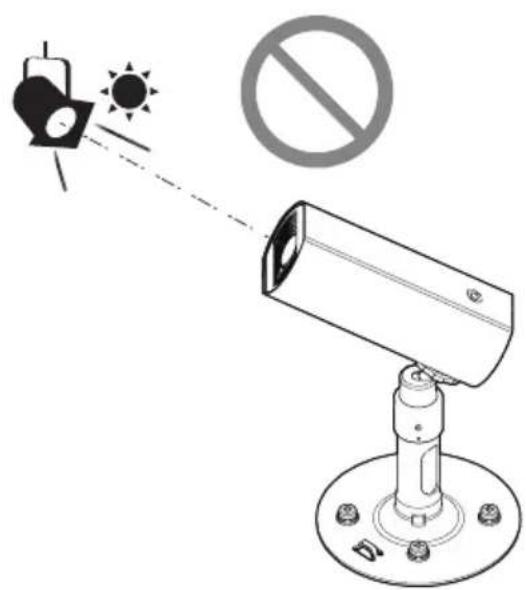
natural_image
Technical line drawing of a mechanical assembly with a cylindrical component and mounting flange (no text or symbols)natural_image
Technical line drawing of a mechanical device with a cylindrical component and mounting base (no text or symbols)natural_image
Technical line drawing of a hollow cylindrical mechanical part with a recessed hexagonal hole (no text or symbols)WV-U11550-V3
https://www.i-pro.com/
Authorised Representative in EU: i-PRO EMEA B.V.
Laarderhoogtweg 25, 1101 EB Amsterdam, Netherlands
i-PRO EMEA B.V. UK Branch 1010 Cambourne Business Park, Cambridgeshire CB23 6DP

https://i-pro.com/products_and_solutions/en/surveillance/learning-and-support/knowledge-base/safety-instructions
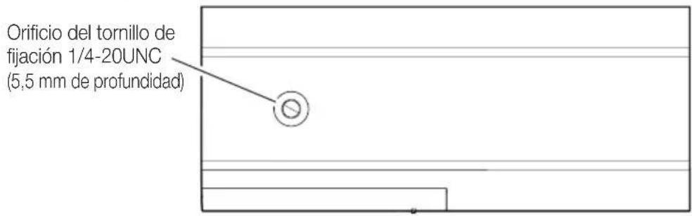
Technical Support Video
Partes y funciones
U11550L
13501350
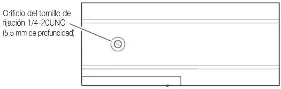
Technical Support Video
Partes y funciones
U11501U
13011301
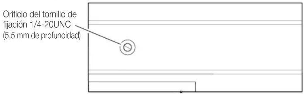
natural_image
Pure electrical circuit lines without any symbolsTechnical Support Video
Partes y funciones
U11301F
natural_image
Pure electrical circuit lines without any symbolsnatural_image
Technical line drawing of a mechanical assembly with a cylindrical component and flanged housing (no text or symbols)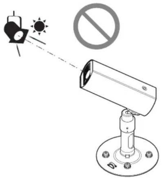
natural_image
Technical line drawing of a mechanical assembly with a cylindrical component and mounting flange (no text or symbols)natural_image
Technical line drawing of a mechanical device with a cylindrical component and mounting base (no text or symbols)natural_image
Technical line drawing of a cylindrical mechanical part with a recessed hole and a small protrusion (no text or symbols)WV-U11550-V3
https://www.i-pro.com/
Authorised Representative in EU: i-PRO EMEA B.V.
Amsterdam, Netherlands
i-PRO EMEA B.V. UK Branch
1010 Cambourne Business Park,
Cambridgeshire CB23 6DP


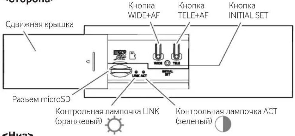
Technical Support Video
Части и функции
U11550U
13501350
natural_image
Pure geometric diagram with horizontal lines and a circle, no text or symbols present<Сторона>
Technical Support Video
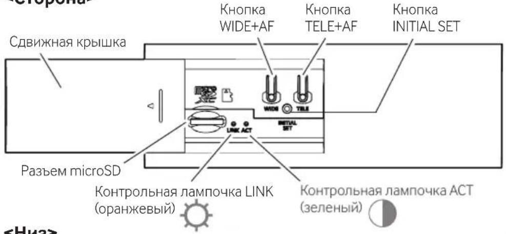
Части и функции
U11501U
13011301
natural_image
Pure geometric diagram with horizontal lines and a small circle, no text or symbols present
<Сторона>
natural_image
Pure electrical circuit lines without any symbolsTechnical Support Video
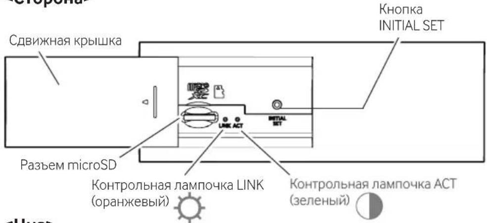
Части и функции
U11301F
natural_image
Pure geometric diagram with horizontal lines and a circle, no text or symbols present
<Сторона>
natural_image
Pure electrical circuit lines without any symbolsnatural_image
Technical line drawing of a mechanical assembly with a cylindrical component and flanged housing (no text or symbols)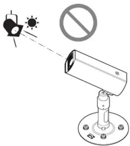
natural_image
Technical line drawing of a mechanical assembly with a cylindrical component and mounting flange (no text or symbols)natural_image
Technical line drawing of a mechanical device with a cylindrical component and mounting base (no text or symbols)


- Network Camera
- About the user manuals
- i-PRO Co., Ltd.
- About notations and model number explanation
- Trademarks and registered trademarks
- Disposal of Old Equipment and Batteries
- Only for European Union and countries with recycling systems
- Note for the battery symbol (bottom symbol)
- For U.S.A.
- Supplier's Declaration of conformity
- For Canada
- Caution: Notice:
- Precautions
- Precautions for installation
- ■ About static electricity
- Standard accessories
- Other items that are needed (not included)
- Optional accessories
- Troubleshooting
- Installation Procedure
- Parts and functions
- Installation method
- Step 1 Preparations
- Step 1 Preparations (Continued)
- If necessary, insert a microSD memory card.
- Step 2
- Step 3
- Step 4
- Step 5
- Step 6
- → Turn the power on (PoE).
- Step 7
- Pour U.S.A.
- Attention: Remarque:
- Pièces et fonctions
- Installationshandbuch
- Bedienerhandbücher
- Parti e funzioni
- Partes y funciones
- Части и функции
Brand : i-PRO
Model : WV-U11350-V3
Category : Surveillance Camera