Smart Lock S230 - Smart Home eufy - Free user manual and instructions
Find the device manual for free Smart Lock S230 eufy in PDF.

| Product Type | Smart Lock |
| Brand | Eufy |
| Model | Smart Lock S230 |
| Use | Interior/Exterior door |
| Power Supply | Rechargeable lithium-ion battery (charges via micro USB port) |
| Charging Time | Approximately 6 hours |
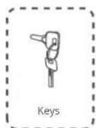
| Unlocking Methods | Fingerprint, touch keypad, physical key, eufy Security mobile app |
| Connectivity | Bluetooth |
| Compatibility | eufy Security app (iOS/Android) |
| Display | Touch screen for code entry, status LED (blue: unlocked, orange: locked, red: anomaly) |
| Operating Temperature | -10°C to 50°C (charging: 0°C to 40°C) |
| Certification | FCC, IC, Industry Canada CNR |
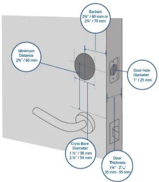
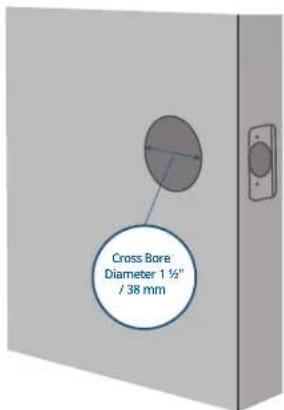
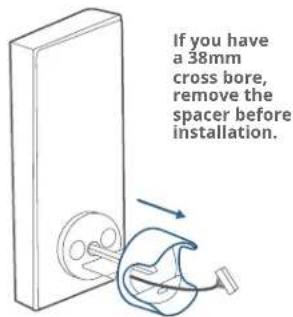
| Installation | Requires standard drilling (door hole 1" / 25mm, cross bore 1.5" / 38mm, door thickness 1.75" - 2.5" / 35 - 55mm) |
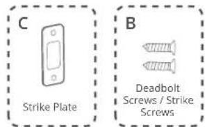
| Box Contents | Deadbolt, strike plate, mounting plates, screws, battery, cable, silicone plug |
| Maintenance | Clean with a soft dry cloth. Avoid extreme temperatures and humidity. |
| Security | Auto-lock, burglary attempt alert (via app) |
| Recycling | Do not dispose of with household waste. Deposit at an approved recycling point. |
Frequently Asked Questions - Smart Lock S230 eufy
User questions about Smart Lock S230 eufy
0 question about this device. Answer the ones you know or ask your own.
Ask a new question about this device
Download the instructions for your Smart Home in PDF format for free! Find your manual Smart Lock S230 - eufy and take your electronic device back in hand. On this page are published all the documents necessary for the use of your device. Smart Lock S230 by eufy.
USER MANUAL Smart Lock S230 eufy
Anker Innovations Limited. All rights reserved, euly Security and euly Security Logo are
trademarks of Anker Innovations Limited, registered in the United States and other
countries. All other trademarks are the property of their respective owners.
PAP 22
Raccolta Carta
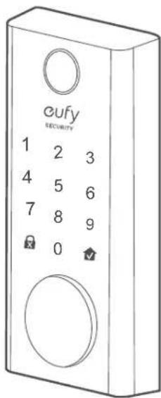
① One-touch Locking Button
② Status Light
• Blue: Door unlocked
• Orange: Door locked
• Red: Abnormal state
③ Reboot Button
④ Micro USB Port
⑤ Fingerprint LED
⑥ Fingerprint Button
⑦ Touchscreen
⑧ Cylinder
⑨ Cylinder Cover
Rear View
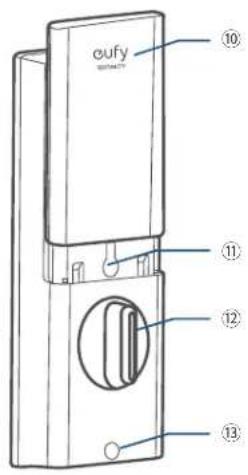

⑩ Battery Cover
⑪ Setup Button
⑫ Thumbturn
⑬ Screw Hole
⑭ QR Code
⑮ Serial Number
01 EN EN
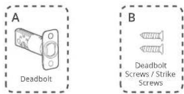
WHAT'S INCLUDED
For Smart Lock Installation
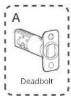
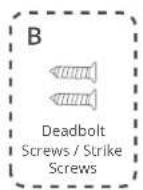
Step 2. Deadbolt Installation Set

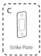
Step 3. Strike Plate Installation Set
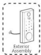
Step 4. Exterior Assembly
03 EN EN
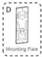
Step 5. Mounting Plate Installation Set
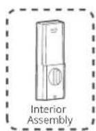
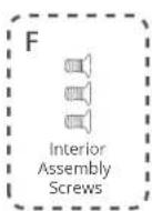
Step 6. Interior Assembly Installation Set

Make sure to use eufy deadbolt and screw fittings, otherwise it may cause usage problems.
INSTALLATION
Step 1. Prepare the Door
- Remove the existing lock and check your door.
- Check if your door has holes like the one below. Standard US doors are already compatible.
- If not, follow the template to drill holes on your door.
05 EN EN
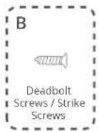
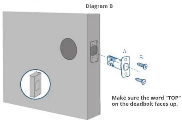
Step 2. Install Deadbolt
- Check your door to see if the deadbolt requires adjustment.
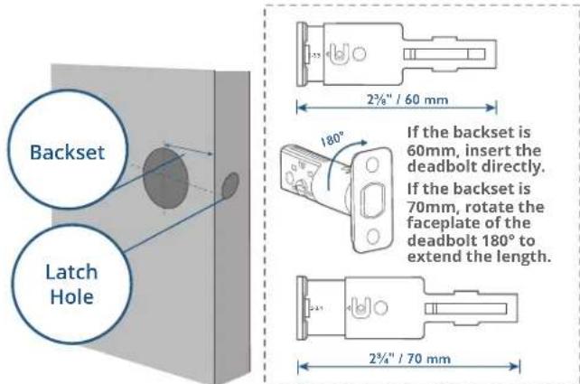
- Insert and screw the deadbolt into the doorframe.
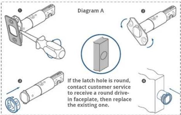
*Check the latch hole before inserting the deadbolt. If the latch hole is round, refer to Diagram A. If the latch hole is rectangular, refer to Diagram B.
07 EN EN
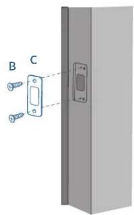
Step 3. Install the Strike Plate
If you have an existing strike plate installed, skip this step. To install the strike plate:
-
Align the strike plate with the center hole of the deadbolt.
-
Secure the strike plate with strike screws. Make sure the plate is placed in the correct direction.
Step 4. Install Exterior Assembly
09 EN EN
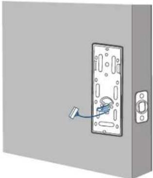
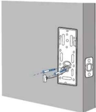
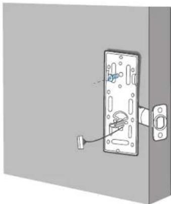
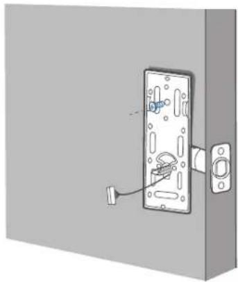
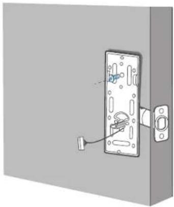
Step 5. Install the Mounting Plate
- Route the cable through the mounting plate.
natural_image
Illustration of a door lock mechanism with a blue tool inserted, no text or symbols present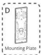
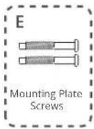
- Tightly fasten the screws in place. Set the screws with your hands, then use a screwdriver to secure them.
natural_image
Diagram of a door with a tool inserted into the lock, showing no text or symbols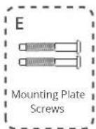
natural_image
Diagram of a door lock assembly with a handle and socket (no text or symbols)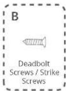
Optional: If the mounting plate is not fastened tightly to the door, use an additional screw (B).
11 EN EN
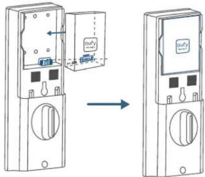
Step 6. Install the Interior Assembly
To install the Interior Assembly:
- Remove the battery cover.
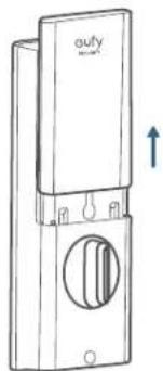
natural_image
Line drawing of a door switch with a circular vent and handle, no text or symbols present- Match the wire connector from the circuit board with the one from the interior assembly as illustrated. The wire connector can only be plugged into the socket in one way. Make sure you match the dot on the connector with the pin on the circuit board correctly.
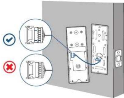
Note: Check carefully whether the wire is stuck or tangled. If the wire is stuck, re-install the Interior Assembly.
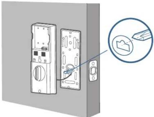
- Align the tailpiece with the key cylinder.
natural_image
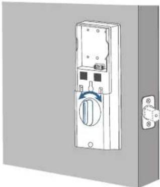
Diagram of a door lock mechanism with a magnified inset showing a close-up of the lock (no text or symbols present)- Turn the thumbturn to check whether the deadbolt is retracted. If the deadbolt does not work smoothly, adjust the screws and install the mounting plate again.
natural_image
Illustration of a wall-mounted electrical switch with a circular button and mounting bracket (no text or symbols)13 EN EN
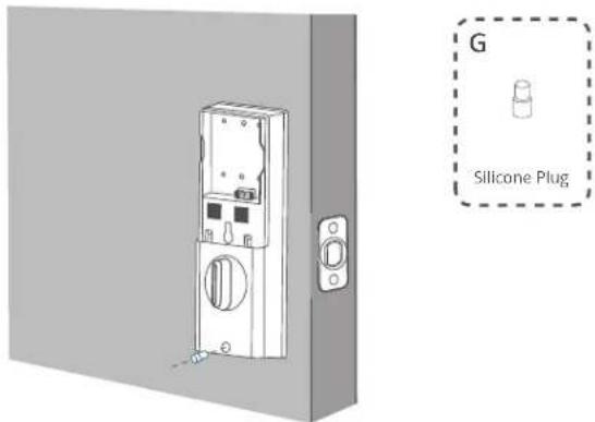
- Secure the provided screws into the interior assembly.
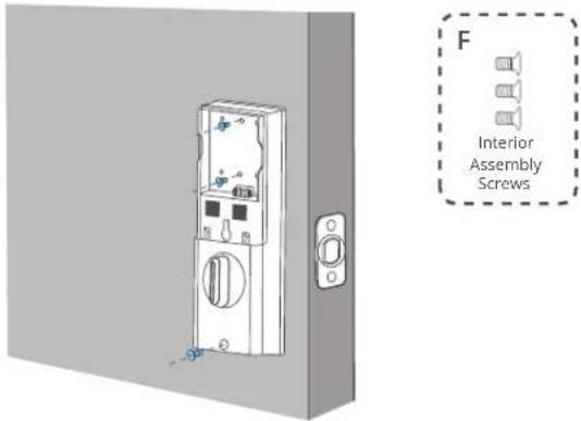
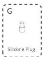
- Use the plug to cover the screw hole at the bottom of the Smart Lock.
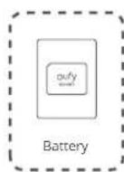
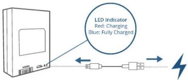
Step 7. Install the Battery
- Fully charge the battery before first use. It might take about 6 hours.
- Align the pin connector on the battery with the pin as illustrated below and slide the battery into the battery compartment.
15 EN EN
SETTING UP THE SYSTEM
- Download and install the eufy Security app, then sign up for an account.


- Follow the in-app instructions to add the S230 / S231 Smart Lock to your device list.
- Please visit https://support.eufylife.com/s/ or scan the QR code for more information.

NOTICE
Do not use the Device in the environment at too high or too low temperature, never expose the Device under strong sunshine or too wet environment.
The suitable temperature for the product and accessories is -10^ to 50^ (Charging temperature: 0^ to 40^ ).
When supplying, please place the device in an environment that has a normal room temperature and good ventilation.
It is recommended to supply the device in an environment with a temperature that ranges from 5^ C - 25^ C ( 41^ F - 77^ F).
The equipment is only suitable for mounting at heights ≤ 2 m.
Do not use the product in any way other than described herein in order to avoid personal injury or property damage.
User should comply with the laws and regulations of the corresponding countries and regions where the equipment is located (used), abide by professional ethics, pay attention to safety obligations, and strictly prohibit the use of our products or equipment for any illegal purposes. Our company will not be responsible for any violators' legal liability under any circumstances.

This product is designed and manufactured with high quality materials and components, which can be recycled and reused.

This symbol means the product must not be discarded as household waste, and should be delivered to an appropriate collection facility for recycling. Proper disposal and recycling helps protect natural resources, human health and the environment. For more information on disposal and recycling of this product, contact your local municipality, disposal service, or the shop where you bought this product.
Warning:
- replacement of a battery with an incorrect type that can defeat a safeguard;
- disposal of a battery into fire or a hot oven, or mechanically crushing or cutting of a battery, that can result in an explosion;
– leaving a battery in an extremely high temperature surrounding environment that can result in an explosion or the leakage of flammable liquid or gas; and - a battery subjected to extremely low air pressure that may result in an explosion or the leakage of flammable liquid or gas.
Attention:
CAUTION RISK OF EXPLOSION IF BATTERY IS REPLACED BY AN INCORRECT TYPE. DISPOSE OF USED BATTERIES ACCORDING TO THE INSTRUCTIONS

ATTENTION RISQUE D'EXPLOSION SI LA BATTERIE EST REMPLACÉE PAR UN TYPE INCORRECT. ÉLIMINER LES BATTERIES USÉES SELON LES INSTRUCTIONS
FCC Statement
This device complies with Part 15 of the FCC Rules. Operation is subject to the following two conditions: (1) this device may not cause harmful interference, and (2) this device must accept any interference received, including interference that may cause undesired operation.
Warning: Changes or modifications not expressly approved by the party responsible for compliance could void the user's authority to operate the equipment.
Note: This equipment has been tested and found to comply with the limits for a Class B digital device, pursuant to Part 15 of the FCC Rules. These limits are designed to provide reasonable protection against harmful interference in a residential installation.
This equipment generates uses and can radiate radio frequency energy and, if not installed and used in accordance with the instructions, may cause harmful interference to radio communications. However, there is no guarantee that interference will not occur in a particular installation. If this equipment does cause harmful interference to radio or television reception, which can be determined by turning the equipment off and on, the user is encouraged to try to correct the interference by one or more of the following measures: (1) Reorient or relocate the receiving antenna. (2) Increase the separation between the equipment and receiver. (3) Connect the equipment into an outlet on a circuit different from that to which the receiver is connected. (4) Consult the dealer or an experienced radio/TV technician for help.
FCC Radio Frequency Exposure Statement
The device has been evaluated to meet general RF exposure requirements. The device can be used in fixed/mobile exposure condition. The min separation distance is 20cm.
Notice: Shielded cables
All connections to other computing devices must be made using shielded cables to maintain compliance with FCC regulations.
The following importer is the responsible party
Company Name: POWER MOBILE LIFE, LLC
Address: 10900 NE 8th St, Ste 501, Bellevue WA 98004
Telephone:1-800-988-7973
IC Statement
This device complies with Industry Canada licence-exempt RSS standard(s).
Operation is subject to the following two conditions:
(1) this device may not cause interference, and
(2) this device must accept any interference, including interference that may cause undesired operation of the device.
This Class B digital apparatus complies with Canadian ICES-003.
When using the product, maintain a distance of 20cm from the body to ensure compliance with RF exposure requirements.
Contenido
Para instalar la cerradura inteligente
natural_image
3D illustration of a door with a lock and handle, no text or symbols present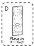
natural_image
Diagram of a door lock with a tool inserted, showing no text or symbols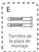
natural_image
Diagram of a door lock mechanism with a handle and mounting bracket (no text or symbols)natural_image
Line drawing of a door switch with a circular vent and an upward arrow indicator (no text or symbols)natural_image
Diagram of a door lock mechanism with a magnified inset showing a tool interacting with a component (no text or symbols present)natural_image
3D diagram of a wall-mounted electrical switch with a rotary knob and mounting bracket (no text or symbols)natural_image
Illustration of a door-mounted electrical switch with a mounted panel and side button (no text or symbols)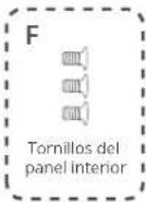
natural_image
Illustration of a door-mounted electrical switch with mounting bracket (no text or symbols)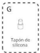
33 ES ES
CONFIGURACIÓN
35 ES ES
AVISO
The device has been evaluated to meet general RF exposure requirements. The device can be used in fixed/mobile exposure condition. The min separation distance is 20cm.
Notice: Shielded cables
All connections to other computing devices must be made using shielded cables to maintain compliance with FCC regulations.
The following importer is the responsible party
natural_image
Illustration of a door lock mechanism with a blue tool inserted (no text or symbols)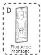
natural_image
Diagram of a door with a tool inserted into the lock, showing no text or symbols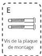
natural_image
Diagram of a door lock mechanism with a handle and socket, showing no text or symbols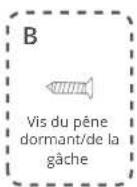
natural_image
Line drawing of a door switch with a circular vent and handle, showing no text or symbolsnatural_image
Diagram of a door lock system with a magnified inset showing a tool interacting with a folder (no text or symbols present)natural_image
Diagram of a door switch with a blue circular knob and mounting bracket (no text or symbols)51 FR FR
53 FR FR
Mise
AVIS
Adresse: 10900 NE 8th St, Ste 501, Bellevue WA 98004
Telephone: 1-800-988-7973
Déclaration IC
(US) +1 (800) 988-7973
(UK) +44 (0) 1604 936200
(DE) +49 (0) 69 9579 7960
(中国)+86 400 0550 036
(日本)+81 03 4455 7823
(AU) +61 3 8331 4800
(Egypt) +20 8000000826
(UAE) +971 8000320817
(Kuwait) +965 22069086
(Saudi Arabia) +966 8008500030
(Middle East & Africa) +971 520750842

support@eufy.com
Anker Innovations Limited
Room 1318-19, Hollywood Plaza, 610 Nathan Road, Mongkok, Kowloon, Hong Kong

@EufyOfficial @EufyOfficial @EufyOfficial
For tutorial videos, FAQs, manuals, and more information, please visit: https://support.anker.com Or scan the QR code below: