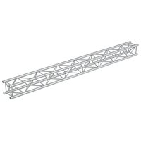
P30 - Modular stage structure BeamZ - Free user manual and instructions
Find the device manual for free P30 BeamZ in PDF.


| Product Type | Modular stage structure (aluminum truss) |
| Brand | BeamZ |
| Model | P30 |
| Material | Aluminum (alloy compliant with EN 1999) |
| Intended Use | Temporary or permanent assemblies to support loads (lifting accessory or construction product) |
| Assembly System | Conical couplers, conical end fittings, safety pins (BeamZ patented system) |
| Approximate Dimensions | Square section 30 cm, modular lengths (up to 3 meters standard) |
| Indicative Weight | Approximately 5 kg per linear meter (depending on configuration) |
| Maximum Load | Varies according to setup; must be calculated by a structural engineer (refer to the provided structural report) |
| Applicable Standards | Machinery Directive 2006/42/EC, Construction Regulation 305/2011/EC, EN 1999, EN 1090 |
| Maintenance | Visual inspection before each use, annual periodic inspection by a competent person |
| Cleaning | Regular cleaning with non-aggressive products; sandblasting or shot blasting prohibited |
| Safety | Use PPE (helmet, gloves, safety shoes); climbing without fall protection prohibited; do not exceed load limits |
| Storage | Away from acids, aggressive materials, extreme temperatures; on suitable carts |
| Transport | Protect against shocks, slips, and falls; use PPE |
| Compatible Accessories | Hooks, clamps, dedicated BeamZ lifting systems |
| Spare Parts and Repairability | Conical couplers, conical end fittings, safety pins, springs; replace only with original parts; discard if damaged |
| General Information | Instruction manual available in several languages; warranty void if instructions not followed |
Frequently Asked Questions - P30 BeamZ
User questions about P30 BeamZ
0 question about this device. Answer the ones you know or ask your own.
Ask a new question about this device
Download the instructions for your Modular stage structure in PDF format for free! Find your manual P30 - BeamZ and take your electronic device back in hand. On this page are published all the documents necessary for the use of your device. P30 by BeamZ.
USER MANUAL P30 BeamZ
SAFETY INSTRUCTIONS 4
TRANSPORT AND STORAGE 4
TRUSS ACCESSORIES 4
COATINGS....4
ASSEMBLY 5
DISASSEMBLY 5
SLINGING OF TRUSS 6
ATTACHING LOADS....6
INSPECTION OF TRUSS 6
REJECTION CRITERIA 7
DO'S AND DON'T 9
DISCLAIMER....9
NEDERLANDS
INLEIDING 10
TOEPASSING 10
IDENTIFICATIE TRUSS....10
BEPERKING VAN HET GEBRUIK....10
RECUBRIMIENTOS....22
MONTAJE 23
DESMONTAJE 23
COLGAR EL TRUSS....24
This trussing left our factory in perfect condition. If transport damages should be present, do not use this product and contact your specialized dealer.
Beamz trusses are used for event and production purpose. Before installing and operating a P30/P32/P33 truss, read this manual carefully and pay attention to all provided information. Use this manual to get familiar with the products, how to properly use the truss and follow all safety regulations. Manuals should be available at all times for all users and employees.
The warranty claim expires with damage, which is caused by neglect of the instructions. The manufacturer does not assume any liability for the damages resulting from it.
SCOPE
P30/P32/P33 trusses are designed to be repeatedly assembled and disassembled in order to carry loads in temporary or permanent installations. Depending on the application P30/P32/P33 trusses can be judged as lifting accessories or construction products. If used as lifting accessories, trusses are subjected to the European Machine Directive 2006/42/EC. If trusses are used as construction products in a temporary or permanent construction they are subjected to the European Construction Regulation 305/2011/EC.
It shall be noted that it is the sole responsibility of the client to check with local authorities if the legislation used by BEAMZ is acceptable in the country of use.
IDENTIFICATION TRUSS
The P30/P32/P33 Truss has a sticker with marked type of truss and date of production.
LIMITATION OF USE
The P30/P32/P33 Truss should be used according to the limits specified in the structural report and the provided declarations. All other structures that are made of truss elements need to have dedicated structural reports. The legal compliance of an construction made from different brands is the sole responsibility of the user and has to be always certified by a structural engineer. Beamz cannot take over the responsibility for products manufactured by other producers. Our design and certification is made in accordance to latest European standards EN-1999 and EN-1090.
P30/P32/P33 truss is not designed for lifting people in general.
Safety precaution and load reduction should be taken into account when lifting people. Temperatures below 0degrees can cause damage to the truss. In an aggressive environment special attention is needed. Following situation should be avoided:
- Direct contact with concrete
- Direct contact with salty water
• While coating or anodizing the structure no salt water should get in contact with the material
SAFETY INSTRUCTIONS
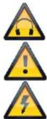
Adequate Personal Protection Equipment is required during assembly, disassembly, maintenance and transportation of truss. Hard heads, gloves, sound protection and safety shoes should be always used!
Do not use any damaged or malfunctioning truss.
The client has ensure that the truss systems are incorporated in a common potential equalisation system which should be connected to the earth wire of the electrical power supply system. Grounding the truss is very important in order to avoid getting in direct contact of people with the electrically charged suspended fixtures.
TRANSPORT AND STORAGE
Trusses must be protected against all mechanical damages or affecting external influences like acid or any aggressive materials or temperatures. Storage of trusses has to be done properly in order to protect all material from harming influences or situations.
It is not allowed to drop, drag or throw the truss. During transportation trusses have to be secured against any bumping, sliding or falling down. Use always the PPE as described in "SAFETY INSTRUCTIONS".
TRUSS ACCESSORIES
Pay always special attention while connecting accessories with the truss like hooks and clamps that they are dedicated to the used truss type and do not harm the truss.
COATINGS
Chemical removal of coatings and surface finishes shall be carried out only after consulting with the chemical manufacturer to ensure that the chemical will not affect the mechanical properties of the aluminium. Abrasion blasting and sanding of P30/P32/P33 trusses is not allowed.
ASSEMBLY
Beamz truss are designed user friendly and offer a convenient assembly. Nevertheless working with a truss construction requires a certain professional knowledge. Please do not attempt to work with truss if lack knowledge; contact a rigging specialist for assistance.
- Check the truss, conical couplers, conical spigots and safety springs for any damages. If any piece is damaged, do not use it and have it examined by a specialist or replace it with an original Beamz product.
- Align the truss on an even surface.
- Check that you have all the necessary parts, including conical couplers, conical spigots, safety springs.
- Insert a conical half-way into a main chord and check that the drillings in the conical are aligned with the drilling in the main chord. The larger hole in the conical must face outwards.
- Insert now a conical spigot with the narrow side down and push it through. For a tolerance free connection, use a copper hammer to drive the pin completely in the cone of main chord.

WARNING: Do not use a steel hammer as this may damage the conical spigots and truss. Avoid using unnecessary force when tapping on conical spigots; this can also lead to damage! Joggling the end up and down and from side to side is more effective.
- Push a safety spring through the small hole of the conical spigot. This secures the pin so that it cannot fall out.
- Repeat this step for each main chord. You might have to turn the truss to insert all conical spigots and safety springs.
- Insert now the truss with the conical side into the next truss you want to add and secure the main chord of the second truss as well with all conical spigots and safety springs.
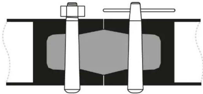
Noted: If you are using a Beamz conical spigot with thread system (e.g. 182.383) then you can use the same methods as described above. Make sure the nut is fixed on the screw, but not too tight, as it may damage your truss.
natural_image
Pure mechanical assembly diagram showing two vertical cylindrical components with flanges and a central hexagonal component (no text or symbols)DISASSEMBLY
- Remove all the safety springs.
- Push truss pins from the inside to the outside and remove them. (If you use a copper hammer to drive the pin out, be careful as the truss pin might fly off when you knock hard with the hammer)
- Loosen the connection and pull the truss apart.
- Collect and store all conical couplers, conical spigots, safety springs.
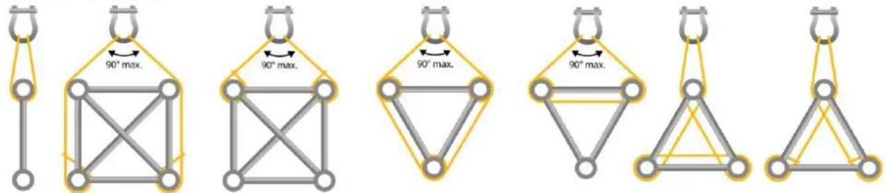
SLINGING OF TRUSS
Slinging should be done properly and with soft surface and fire retardant slings. Minimum 2 main chords should be wrapped around.
ADVICED SLINGING METHODS
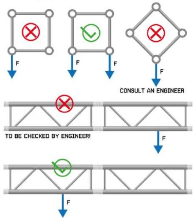
ATTACHING LOADS
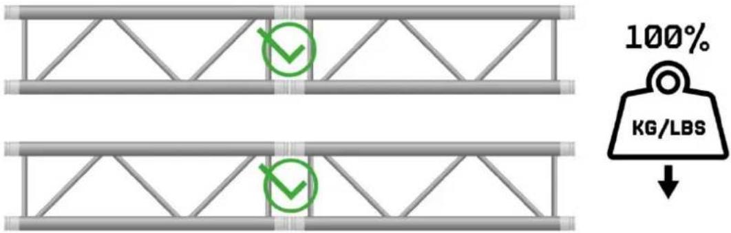
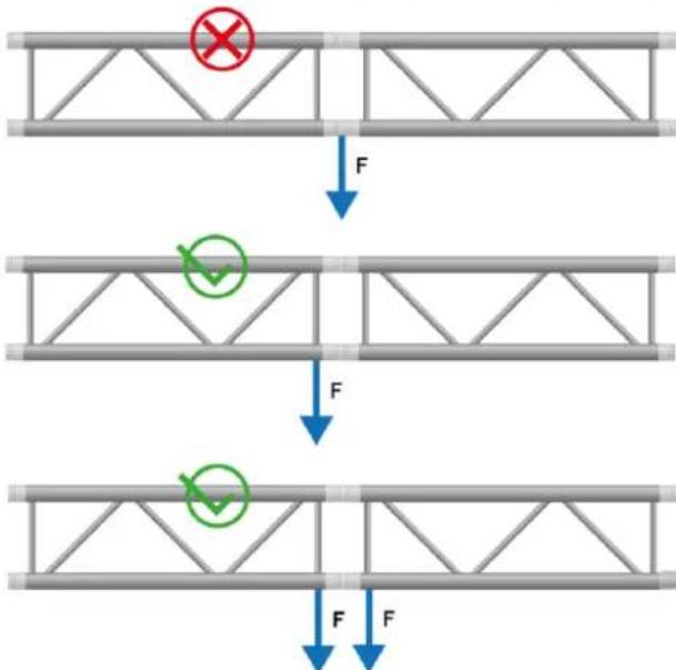
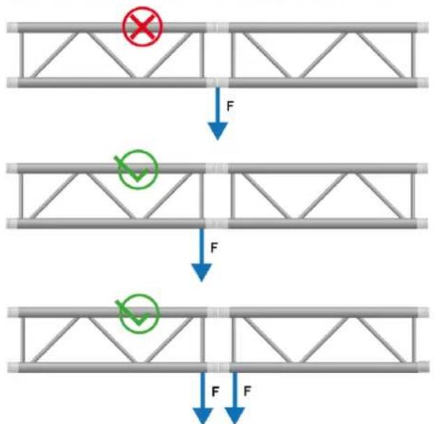
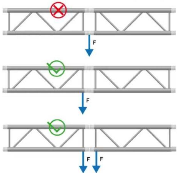
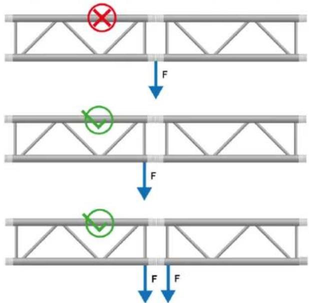
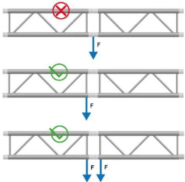
Loads must be equally distributed over the main chords. Loading a truss on one chord leads to internal torsional forces that are not included in the data and calculations provided.
flowchart
graph TD
    A["Start"] --> B{Check}
    B -->|F| C["To be checked by engineer!"]
    B -->|✓| D["Check to check"]
    D --> E["Consult an engineer"]
    E --> F["End"]
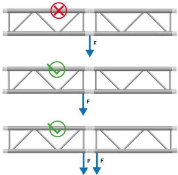
ANY LOADS NEAR THE CONNECTOR SHOULD BE DONE AS SHOWN BELOW:
flowchart
graph TD
    A["Start"] --> B{Checkmark}
    B -->|F| C["Step 1"]
    C --> D{Checkmark}
    D -->|F| E["Step 2"]
    E --> F["End"]
INSPECTION OF TRUSS
A documented inspection by a competent person should be done at least once a year or more often if required by any other circumstances.
The inspection should be done according machine directive EC 2006/42 and local legal rules for truss used as lifting equipment.
For permanent structures the inspection should be done according to EC 2011/305 directive. As often as it is required the inspections should be made according to all local legal and building rules. The P30/P32/P33 truss have to be checked visually for any damage that can have an impact on the safety, each time before use!
The user is predominantly responsible for safe use of truss elements. Before EACH assembly it is necessary to check the truss elements, connection parts and all other accessories.

IT IS FORBIDDEN TO USE DAMAGED TRUSS, CONICAL COUPLERS, SPIGOTS AND/OR SAFETY SPRINGS!
Initial inspection of any new or acquired used truss:
• the elements should be inspected and a record should be done.
Regular visual inspections:
- should be done by a competent person before each use
Periodic inspection:
- should be done by a competent person at least once a year.

NOTE: Truss that were used in an accident have to be inspected to the requirements of the periodic inspections.
| Inspection level | Items to be inspected | |||||||||
| Part | Initial | Regular | Periodic | Chords | Diagonals | Connectors | Welds | Fasteners | Geometry | ID-TAG |
| Missing parts | √ | √ | √ | √ | ||||||
| Dents | √ | √ | √ | √ | √ | |||||
| Bends | √ | √ | √ | √ | √ | |||||
| Holes (1) | √ | √ | √ | √ | √ | √ | √ | √ | ||
| Incorrect repair | √ | √ | √ | √ | √ | √ | √ | √ | ||
| Abrasion | √ | √ | √ | √ | √ | √ | ||||
| Corrosion | √ | √ | √ | |||||||
| Missing members | √ | √ | √ | √ | √ | √ | √ | |||
| Flatness (2) | √ | √ | √ | √ | ||||||
| Deformation | √ | √ | √ | √ | √ | |||||
| Excessive wear | √ | √ | √ | √ | √ | √ | ||||
| Cracks | √ | √ | √ | √ | ||||||
| Correct grading (3) | √ | √ | √ | √ | ||||||
| Twisting | √ | √ | √ | √ | ||||||
| Squareness | √ | √ | √ | √ | ||||||
| Bending | √ | √ | √ | √ | ||||||
| Sweep | √ | √ | ||||||||
| Camber | √ | √ | ||||||||
(1) not to be part of the construction; (2) particular for trusses with connecting plates; minimum 8.8 grade
FREQUENCY OF INSPECTION
• Truss that are used regularly should be inspected according to regular and periodic inspections.
• All truss and truss constructions that are installed stationary and permanently should be inspected according periodic inspections.
• Permanently installed but moving truss constructions should be inspected once per 3 years.
RECORDS OF INSPECTIONS
The client should keep a register of initial inspections and periodic inspections for each truss element, with written date and signature by the person who made the inspection.
REJECTION CRITERIA
Beside the fact that it is required to use the truss properly during assembly, disassembly, transport storage etc. regular inspections are very important. A detailed visual check of each element before each use should be done. The regular inspections and written records should be done at least once a year by a competent person. However if the truss is used very often the inspection should be done more frequently.
If there any deficiencies during the inspection of the truss it has to be taken out of service and recycled. The criteria to discard the truss should be implemented into the inspection process.
Due to it's nature, The aluminium truss can have some dimensional deviation comparing to original dimensions within the limits given in EN 1090-3.
If any of the below criteria below occur the truss should be taken out of service. In case of any doubt please contact the manufacturer/distributor.
• Missing sticker with truss types, manufacturer info and production date.
- Any deformation of the truss exceeding the allowable limits.
• More than 10% reduction of the raised level of the welding seam by mechanical wear.
• More than 10% reduced cross-sectional area of the truss due to excessive corrosion.

NOTE: Any damaged part should be clearly marked and taken out of service.
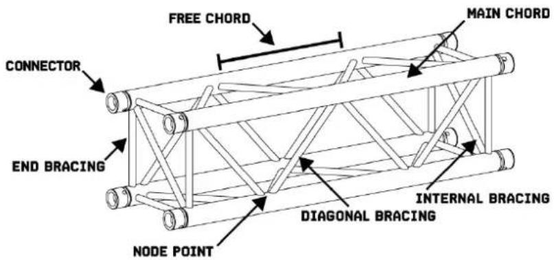
MAIN CHORD
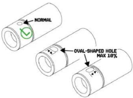
If any cracks or breaks on the main chord occur or if it is rolled more than 10% of the original diameter the truss should be marked and taken out of service. Also, the end section of the truss, where the truss is connected, should not be in such a condition that it can only be connected with much higher force.
Further signs of a discard condition are:
• Any scratches, cuts etc on the main chord that causes reduction of the cross-sectional area of the main chord over 10%.
• Any indentations that are more than 1mm deep and 10mm long.
• Any holes appearing after use of the truss.
• Any deformation from the original shape to an oval shape or indentation by more than 10%.
BRACING
Any brace (diagonal, cross or end brace) is broken or is not there, the truss is not usable anymore.
Further signs of a discard condition are:
• Any scratches, cuts etc on the brace that causes reduction of the cross-sectional area of the brace over 10%.
- Any indentations that are more than 0.5mm deep and 10mm long.
• Any holes appearing after use of the truss.
• Any deformation from the original shape to an oval shape or indentation by more than 10%.
CONNECTOR
Discard conditions:
• Any cracks or breaks on the welding seam between the connector and main pipe.
• Oval signs of wear higher than 10% of the original diameter in the drill holes.
• More than 2 degreed rotational displacement of the drill holes in a connector or 2 adjoining connectors.
• More than 5degrees deflection of the main chords with the connector, make the truss hard to assemble.
- Any signs of use causing reduction of the cross-sectional area of the connector higher 10%.
- Any deformations in the main chord next to the connector welds.
• Too high tensile force may cause domination of the main chord by the welds.
• Buckling caused by overloading with excessive force.
• Any damage, scratch or cut in dentation more than 2mm deep and 10mm long
- Corrosion
CONICAL SPIGOTS
Conical spigots are used very frequently. If any deformations occur they this indicates massive overload. Such bolts cannot be used anymore. Other conditions for discard:
- Any cuts indentations, scratches on the conical spigot surface.
• Any protruding, pointed or sharp edges on the narrow end of the conical spigot. - Deformation cause by hammering.
- Corrosion.
DO'S AND DON'T
DO
• Clean, check and maintain your truss on a regular basis, as this will improve ease of assembly and its lifetime.
- Throw away damaged or deformed truss.
• Make a structural calculation for each construction you build.
• Store and transport your truss on proper dollies.
• Use copper hammers for assembling, as this will reduce damage to the truss.
- Attach loads in node points solely.
- Check how loads are attached to the truss before lifting.
DON'T!
• Mix type truss and/or use multiple suppliers in one construction.
- Exceed the maximum loading and given structural data.
- Drill holes in truss.
- Use damaged truss.
• Climb on truss while attaching yourself to a truss without taking specific measures to bear loads caused by fall arrest equipment.
- Attach loads to the truss diagonal bracing.
DISCLAIMER
Beamz has made every effort to ensure the accuracy of this manual but accepts no liability for any errors. Beamz reserves the right to change or modify its products or manuals without prior notice.
INLEIDING
natural_image
Pure structural truss diagram with green checkmark symbol (no text or labels)

natural_image
Pure structural truss diagram with green checkmark symbol (no text or labels)natural_image
Pure mechanical assembly diagram showing two vertical components with bolts and a central hexagonal component (no text or symbols)DEMONTEREN
flowchart
graph TD
    A["Start"] --> B{Check}
    B -->|F| C["To be checked by engineer!"]
    B -->|✓| D["Check to check"]
    D --> E["Consult an engineer"]
ANY LOADS NEAR THE CONNECTOR SHOULD BE DONE AS SHOWN BELOW:
flowchart
graph TD
    A["Truss Frame"] -->|F| B{Checkmark}
    B -->|F| C["Truss Frame"]
    C -->|F| D{Checkmark}
    D -->|F| E["Truss Frame"]
INSPECTIE VAN TRUSS
| Inspection level | Items to be inspected | |||||||||
| Part | Initial | Regular | Periodic | Chords | Diagonals | Connectors | Welds | Fasteners | Geometry | ID-TAG |
| Missing parts | √ | √ | √ | √ | ||||||
| Dents | √ | √ | √ | √ | √ | |||||
| Bends | √ | √ | √ | √ | √ | |||||
| Holes (1) | √ | √ | √ | √ | √ | √ | √ | √ | ||
| Incorrect repair | √ | √ | √ | √ | √ | √ | √ | √ | ||
| Abrasion | √ | √ | √ | √ | √ | √ | ||||
| Corrosion | √ | √ | √ | |||||||
| Missing members | √ | √ | √ | √ | √ | √ | √ | |||
| Flatness (2) | √ | √ | √ | √ | ||||||
| Deformation | √ | √ | √ | √ | √ | |||||
| Excessive wear | √ | √ | √ | √ | √ | √ | ||||
| Cracks | √ | √ | √ | √ | ||||||
| Correct grading (3) | √ | √ | √ | √ | ||||||
| Twisting | √ | √ | √ | √ | ||||||
| Squareness | √ | √ | √ | √ | ||||||
| Bending | √ | √ | √ | √ | ||||||
| Sweep | √ | √ | ||||||||
| Camber | √ | √ | ||||||||
CONICAL SPIGOT
Trusses must be protected against all mechanical damages or affecting external influences like acid or any aggressive materials or temperatures. Storage of trusses has to be done properly in order to protect all material from harming influences or situations.
It is not allowed to drop, drag or throw the truss. During transportation trusses have to be secured against any bumping, sliding or falling down. Use always the PPE as described in "SAFETY INSTRUCTIONS".
natural_image
Pure mechanical assembly diagram showing two vertical components with bolts and a central hexagonal component (no text or symbols)DEMONTAGE
flowchart
graph TD
    A["Start"] --> B{Check}
    B -->|F| C["Consult: Engineer"]
    B -->|✓| D["Check: Engineer"]
    C --> E["To be checked by engineer!"]
    D --> E
    E --> F["End"]
ANY LOADS NEAR THE CONNECTOR SHOULD BE DONE AS SHOWN BELOW:
flowchart
graph TD
    A["Truss Structure"] -->|F| B{Checkmark}
    B -->|F| C["Final Force"]
    C -->|F| D["Final Force"]
INSPEKTION DER TRAVERSE
| Inspection level | Items to be inspected | |||||||||
| Part | Initial | Regular | Periodic | Chords | Diagonals | Connectors | Welds | Fasteners | Geometry | ID-TAG |
| Missing parts | √ | √ | √ | √ | ||||||
| Dents | √ | √ | √ | √ | √ | |||||
| Bends | √ | √ | √ | √ | √ | |||||
| Holes (1) | √ | √ | √ | √ | √ | √ | √ | √ | ||
| Incorrect repair | √ | √ | √ | √ | √ | √ | √ | √ | ||
| Abrasion | √ | √ | √ | √ | √ | √ | ||||
| Corrosion | √ | √ | √ | |||||||
| Missing members | √ | √ | √ | √ | √ | √ | √ | |||
| Flatness (2) | √ | √ | √ | √ | ||||||
| Deformation | √ | √ | √ | √ | √ | |||||
| Excessive wear | √ | √ | √ | √ | √ | √ | ||||
| Cracks | √ | √ | √ | √ | ||||||
| Correct grading (3) | √ | √ | √ | √ | ||||||
| Twisting | √ | √ | √ | √ | ||||||
| Squareness | √ | √ | √ | √ | ||||||
| Bending | √ | √ | √ | √ | ||||||
| Sweep | √ | √ | ||||||||
| Camber | √ | √ | ||||||||
CONICAL SPIGOTS
natural_image
Pure structural truss diagram with a green checkmark symbol (no text or labels)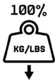

natural_image
Pure structural truss diagram with a green checkmark symbol (no text or labels)natural_image
Pure mechanical assembly diagram showing two vertical components with bolts and a hexagonal base (no text or symbols)DESMONTAJE
flowchart
graph TD
    A["Start"] --> B{Check}
    B -->|F| C["To be checked by engineer!"]
    B -->|✓| D["Check to check"]
    D --> E["Consult an engineer"]
    E --> F["End"]
ANY LOADS NEAR THE CONNECTOR SHOULD BE DONE AS SHOWN BELOW:
flowchart
graph TD
    A["Start"] --> B{Checkmark}
    B -->|F| C["Step 1"]
    C --> D{Checkmark}
    D -->|F| E["Step 2"]
    E --> F{Checkmark}
    F -->|F| G["Step 3"]
| Inspection level | Items to be inspected | |||||||||
| Part | Initial | Regular | Periodic | Chords | Diagonals | Connectors | Welds | Fasteners | Geometry | ID-TAG |
| Missing parts | √ | √ | √ | √ | ||||||
| Dents | √ | √ | √ | √ | √ | |||||
| Bends | √ | √ | √ | √ | √ | |||||
| Holes (1) | √ | √ | √ | √ | √ | √ | √ | √ | ||
| Incorrect repair | √ | √ | √ | √ | √ | √ | √ | √ | ||
| Abrasion | √ | √ | √ | √ | √ | √ | ||||
| Corrosion | √ | √ | √ | |||||||
| Missing members | √ | √ | √ | √ | √ | √ | √ | |||
| Flatness (2) | √ | √ | √ | √ | ||||||
| Deformation | √ | √ | √ | √ | √ | |||||
| Excessive wear | √ | √ | √ | √ | √ | √ | ||||
| Cracks | √ | √ | √ | √ | ||||||
| Correct grading (3) | √ | √ | √ | √ | ||||||
| Twisting | √ | √ | √ | √ | ||||||
| Squareness | √ | √ | √ | √ | ||||||
| Bending | √ | √ | √ | √ | ||||||
| Sweep | √ | √ | ||||||||
| Camber | √ | √ | ||||||||
The client should keep a register of initial inspections and periodic inspections for each truss element, with written date and signature by the person who made the inspection.
CRITERIOS DE RECHAZO
QUE HACER Y QUE NO HACER
HACER
natural_image
Pure structural truss diagram with a green checkmark symbol (no text or labels)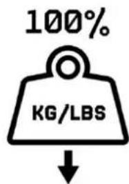

natural_image
Pure structural truss diagram with green checkmark symbol (no text or labels)natural_image
Pure mechanical assembly diagram showing two vertical cylindrical components with fasteners and a central hexagonal component (no text or symbols)DEMONTAGE
flowchart
graph TD
    A["Start"] --> B{Check}
    B -->|F| C["To be checked by engineer!"]
    B -->|✓| D["Check to check"]
    D --> E{Check}
    E -->|F| F["Consult an engineer"]
    E -->|✓| G["End"]
ANY LOADS NEAR THE CONNECTOR SHOULD BE DONE AS SHOWN BELOW:
flowchart
graph TD
    A["Start"] --> B{Checkmark}
    B -->|F| C["Step 1"]
    C --> D{Checkmark}
    D -->|F| E["Step 2"]
    E --> F{Checkmark}
    F -->|F| G["End"]
INSPECTION DES STRUCTURES
| Inspection level | Items to be inspected | |||||||||
| Part | Initial | Regular | Periodic | Chords | Diagonals | Connectors | Welds | Fasteners | Geometry | ID-TAG |
| Missing parts | √ | √ | √ | √ | ||||||
| Dents | √ | √ | √ | √ | √ | |||||
| Bends | √ | √ | √ | √ | √ | |||||
| Holes (1) | √ | √ | √ | √ | √ | √ | √ | √ | ||
| Incorrect repair | √ | √ | √ | √ | √ | √ | √ | √ | ||
| Abrasion | √ | √ | √ | √ | √ | √ | ||||
| Corrosion | √ | √ | √ | |||||||
| Missing members | √ | √ | √ | √ | √ | √ | √ | |||
| Flatness (2) | √ | √ | √ | √ | ||||||
| Deformation | √ | √ | √ | √ | √ | |||||
| Excessive wear | √ | √ | √ | √ | √ | √ | ||||
| Cracks | √ | √ | √ | √ | ||||||
| Correct grading (3) | √ | √ | √ | √ | ||||||
| Twisting | √ | √ | √ | √ | ||||||
| Squareness | √ | √ | √ | √ | ||||||
| Bending | √ | √ | √ | √ | ||||||
| Sweep | √ | √ | ||||||||
| Camber | √ | √ | ||||||||
A FAIRE ET A NE PAS FAIRE
A FAIRE
natural_image
Pure mechanical assembly diagram showing two vertical rods inserted into a housing with a central hexagonal component (no text or symbols)DEMONTAZ
flowchart
graph TD
    A["Start"] --> B{Check}
    B -->|F| C["To be checked by engineer!"]
    B -->|✓| D["Check to check"]
    D --> E["Consult an engineer"]
    E --> F["End"]
ANY LOADS NEAR THE CONNECTOR SHOULD BE DONE AS SHOWN BELOW:
flowchart
graph TD
    A["Start"] --> B{Checkmark}
    B -->|F| C["Step 1"]
    C --> D{Checkmark}
    D -->|F| E["Step 2"]
    E --> F{Checkmark}
    F -->|F| G["Step 3"]
KONTROLA KRATOWNICY
| Inspection level | Items to be inspected | |||||||||
| Part | Initial | Regular | Periodic | Chords | Diagonals | Connectors | Welds | Fasteners | Geometry | ID-TAG |
| Missing parts | √ | √ | √ | √ | ||||||
| Dents | √ | √ | √ | √ | √ | |||||
| Bends | √ | √ | √ | √ | √ | |||||
| Holes (1) | √ | √ | √ | √ | √ | √ | √ | √ | ||
| Incorrect repair | √ | √ | √ | √ | √ | √ | √ | √ | ||
| Abrasion | √ | √ | √ | √ | √ | √ | ||||
| Corrosion | √ | √ | √ | |||||||
| Missing members | √ | √ | √ | √ | √ | √ | √ | |||
| Flatness (2) | √ | √ | √ | √ | ||||||
| Deformation | √ | √ | √ | √ | √ | |||||
| Excessive wear | √ | √ | √ | √ | √ | √ | ||||
| Cracks | √ | √ | √ | √ | ||||||
| Correct grading (3) | √ | √ | √ | √ | ||||||
| Twisting | √ | √ | √ | √ | ||||||
| Squareness | √ | √ | √ | √ | ||||||
| Bending | √ | √ | √ | √ | ||||||
| Sweep | √ | √ | ||||||||
| Camber | √ | √ | ||||||||
CONICAL SPIGOT
- Tüv certification only valid for loading table above.
• The values are characteristic according to Eurocode (European standards). Partial safety factors (1,35/1,5) are considered.
- Interaction of internal forces at connector are considered.
• The table data have no limitation of deflection.
• The loads are only valid for static loads. The system is perfect and secured against lateral bucking.
• All static systems, other than single spans, need an individual structural calculation. Please contact a structural engineer.
• The self-weight of the truss system is considered.
- Loading figures are only valid for single spans with supports at both ends.
• The deflection is calculated for a single truss spann.
- Load application occurs directly in the nodes and both framework sides are loaded equally.
• The values are only valid for the single span girders analysed here. Complex structures are not covered by this!
- Read the manual before assembling, using and loading the truss.
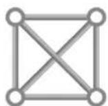
SPECIFICATIONS
CHORDS∅50x2mm
BRACES ∅16x2mm
DIMENSIONS 290x290mm
P32 TRUSS LOADING CHART
The following table applies provided that the truss is secured against lateral buckling every 1.0 m. The load may only be applied on the bottom chord!
| Span width | Uniformly distributed load UDL | Deflection | Centre point load CPL | Deflection | Third point load TPL | Quarter point load QPL | Fifth point load FPL | |||||||
| m | ft | kg/m | lbs/ft | cm | kg | lbs | cm | kg | lbs | kg | lbs | kg | lbs | |
| 2 | 6,56 | 329 | 221 | 0,19 | 658 | 1451 | 0,33 | 329 | 725 | 219 | 483 | 164 | 362 | |
| 3 | 9,84 | 218 | 146 | 0,50 | 646 | 1426 | 0,83 | 328 | 723 | 218 | 482 | 164 | 361 | |
| 4 | 13,12 | 163 | 109 | 1,06 | 483 | 1065 | 1,29 | 326 | 720 | 217 | 480 | 163 | 360 | |
| 5 | 16,40 | 130 | 87 | 1,95 | 384 | 847 | 1,89 | 288 | 635 | 192 | 423 | 160 | 353 | |
| 6 | 19,69 | 106 | 71 | 3,21 | 318 | 701 | 2,63 | 238 | 526 | 159 | 350 | 132 | 292 | |
| 7 | 22,97 | 77 | 51 | 4,29 | 270 | 596 | 3,50 | 203 | 447 | 135 | 298 | 112 | 248 | |
| 8 | 26,25 | 58 | 39 | 5,54 | 234 | 517 | 4,52 | 176 | 388 | 117 | 258 | 97 | 215 | |
| 9 | 29,53 | 45 | 30 | 6,95 | 206 | 455 | 5,68 | 154 | 341 | 103 | 227 | 86 | 189 | |
| 10 | 32,81 | 36 | 24 | 8,54 | 183 | 405 | 6,99 | 137 | 303 | 91 | 202 | 76 | 168 | |
| 11 | 36,09 | 29 | 20 | 10,30 | 164 | 363 | 8,44 | 123 | 272 | 82 | 181 | 68 | 151 | |
| 12 | 39,37 | 24 | 16 | 12,23 | 149 | 328 | 10,50 | 111 | 246 | 74 | 164 | 62 | 136 | |
The following table applies in case the truss is held only at the ends.
| Span width | Uniformly distributed load UDL | Deflection | Centre point load CPL | Deflection | Third point load TPL | Quarter point load QPL | Fifth point load FPL | ||||||
| m | ft | kg/m | lbs/ft | cm | kg | lbs | cm | kg | lbs | kg | lbs | kg | lbs |
| 1 | 3,28 | 660 | 443 | 0,05 | 660 | 1456 | 0,10 | 330 | 728 | 220 | 485 | 165 | 364 |
| 2 | 6,56 | 329 | 221 | 0,19 | 534 | 1178 | 0,27 | 329 | 725 | 219 | 483 | 164 | 362 |
| 3 | 9,84 | 117 | 78 | 0,27 | 175 | 387 | 0,23 | 131 | 290 | 87 | 193 | 73 | 161 |
| 4 | 13,12 | 36 | 24 | 0,25 | 73 | 162 | 0,21 | 55 | 122 | 36 | 81 | 30 | 67 |
| 5 | 16,4 | 14 | 9 | 0,24 | 35 | 77 | 0,21 | 26 | 58 | 17 | 38 | 14 | 32 |
NOTES:
- Tüv certification only valid for loading table above.
• The values are characteristic according to Eurocode (European standards). Partial safety factors (1,35/1,5) are considered. - Interaction of internal forces at connector are considered.
• The table data have no limitation of deflection.
• The loads are only valid for static loads. The system is perfect and secured against lateral bucking.
• All static systems, other than single spans, need an individual structural calculation. Please contact a structural engineer. - The self-weight of the truss system is considered.
- Loading figures are only valid for single spans with supports at both ends.
• The deflection is calculated for a single truss spann. - Load application occurs directly in the nodes and both framework sides are loaded equally.
• The values are only valid for the single span girders analysed here. Complex structures are not covered by this! - Read the manual before assembling, using and loading the truss.
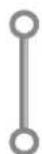
SPECIFICATIONS
CHORDS∅50x2mm
BRACES ∅16x2mm
DIMENSIONS 290x50mm
P33 TRUSS LOADING CHART
| Span width | Uniformly distributed load UDL | Deflection | Centre point load CPL | Deflection | Third point load TPL | Quarter point load QPL | Fifth point load FPL | |||||||
| m | ft | kg/m | lbs/ft | cm | kg | lbs | cm | kg | lbs | kg | lbs | kg | lbs | |
| 3 | 9,8 | 425 | 285 | 0,7 | 565 | 1247 | 0,5 | 394 | 870 | 304 | 670 | 241 | 531 | |
| 4 | 13,1 | 241 | 162 | 1,3 | 436 | 961 | 1,0 | 310 | 685 | 230 | 507 | 184 | 407 | |
| 5 | 16,4 | 153 | 103 | 2,1 | 354 | 780 | 1,5 | 253 | 559 | 184 | 407 | 149 | 330 | |
| 6 | 19,7 | 105 | 71 | 3,0 | 296 | 654 | 2,3 | 214 | 472 | 154 | 339 | 125 | 275 | |
| 7 | 23,0 | 76 | 51 | 4,1 | 254 | 560 | 3,1 | 184 | 407 | 131 | 289 | 107 | 236 | |
| 8 | 26,2 | 58 | 39 | 5,3 | 220 | 486 | 4,1 | 161 | 357 | 113 | 250 | 92 | 204 | |
| 9 | 29,5 | 45 | 30 | 6,8 | 194 | 428 | 5,3 | 143 | 315 | 99 | 219 | 81 | 180 | |
| 10 | 32,8 | 36 | 24 | 8,4 | 172 | 380 | 6,6 | 127 | 280 | 88 | 195 | 72 | 160 | |
| 11 | 36,1 | 29 | 19 | 10,1 | 154 | 340 | 8,1 | 114 | 252 | 78 | 173 | 65 | 143 | |
| 12 | 39,4 | 24 | 16 | 12,1 | 139 | 306 | 9,7 | 103 | 227 | 71 | 156 | 58 | 129 | |
| 13 | 42,7 | 19 | 13 | 14,2 | 125 | 276 | 11,5 | 93 | 207 | 63 | 141 | 52 | 116 | |
| 14 | 45,9 | 16 | 11 | 16,6 | 113 | 250 | 13,5 | 85 | 188 | 57 | 127 | 47 | 105 | |
| 15 | 49,2 | 14 | 9 | 19,1 | 102 | 227 | 15,7 | 78 | 172 | 52 | 115 | 43 | 96 | |
| 16 | 52,5 | 12 | 8 | 21,7 | 93 | 206 | 18,1 | 71 | 156 | 47 | 105 | 39 | 87 | |
NOTES:
- Tüv certification only valid for loading table above.
The values are characteristic according to Eurocode (European standards). Partial safety factors (1,35/1,5) are considered.
- Interaction of internal forces at connector are considered.
• The table data have no limitation of deflection.
• The loads are only valid for static loads. The system is perfect and secured against lateral bucking.
• All static systems, other than single spans, need an individual structural calculation. Please contact a structural engineer.
- The self-weight of the truss system is considered.
- Loading figures are only valid for single spans with supports at both ends.
• The deflection is calculated for a single truss spann.
- Load application occurs directly in the nodes and both framework sides are loaded equally.
• The values are only valid for the single span girders analysed here. Complex structures are not covered by this!
- Read the manual before assembling, using and loading the truss.
SPECIFICATIONS
CHORDS∅50x2mm
BRACES ∅16x2mm
DIMENSIONS 290x290mm
BEAMZ
offers a wide range of high performance lighting equipment and related accessories for the rental, entertainment and architectural lighting markets. BeamZ Pro stands for performance, innovation and value pricing!
- NEDERLANDS
- SCOPE
- IDENTIFICATION TRUSS
- LIMITATION OF USE
- SAFETY INSTRUCTIONS
- TRANSPORT AND STORAGE
- TRUSS ACCESSORIES
- COATINGS
- ASSEMBLY
- DISASSEMBLY
- SLINGING OF TRUSS
- ATTACHING LOADS
- INSPECTION OF TRUSS
- IT IS FORBIDDEN TO USE DAMAGED TRUSS, CONICAL COUPLERS, SPIGOTS AND/OR SAFETY SPRINGS!
- FREQUENCY OF INSPECTION
- RECORDS OF INSPECTIONS
- REJECTION CRITERIA
- MAIN CHORD
- BRACING
- CONNECTOR
- CONICAL SPIGOTS
- DO'S AND DON'T
- DO
- DON'T!
- DISCLAIMER
- INLEIDING
- DEMONTEREN
- INSPECTIE VAN TRUSS
- CONICAL SPIGOT
- DEMONTAGE
- INSPEKTION DER TRAVERSE
- DESMONTAJE
- CRITERIOS DE RECHAZO
- QUE HACER Y QUE NO HACER
- HACER
- INSPECTION DES STRUCTURES
- A FAIRE ET A NE PAS FAIRE
- A FAIRE
- DEMONTAZ
- KONTROLA KRATOWNICY
- SPECIFICATIONS
- P32 TRUSS LOADING CHART
- NOTES:
- BEAMZ
Brand : BeamZ
Model : P30
Category : Modular stage structure