
IC-U20SR - Portable transceiver radio ICOM - Free user manual and instructions
Find the device manual for free IC-U20SR ICOM in PDF.

| Product type | PMR446 portable transceiver |
| Brand | ICOM |
| Model | IC-U20SR |
| Frequency range | 446.006250 ~ 446.193750 MHz (PMR446 band) |
| Transmit power | 0.5 W (ERP) |
| Number of channels | 16 channels with preprogrammed CTCSS tones |
| Dimensions (W × H × D) | 50.0 × 94.0 × 26.7 mm (without protrusions) |
| Weight | 157 g (with battery); 168 g (with belt clip) |
| Battery | BP-304A Lithium-ion 3.6 V, 2,200 mAh (min) / 2,350 mAh (typical) |
| Estimated battery life | Approx. 21 hours (TX:RX:standby = 5:5:90 with power save) |
| Protection rating | IP54 (dust-tight and splash-resistant, with connector covers attached) |
| Power supply | Built-in rechargeable battery; charging via USB-C (5 V/1 A) or BC‑262/BC‑264 drop-in charger |
| Charging time | Approx. 5.5 h (USB 5 V/1 A); approx. 3.8 h (BC‑264 rapid charger) |
| Main functions | Intelligent call, call bell, key lock, VOX, scanning, backlight, monitor, squelch adjustment, microphone gain, etc. |
| Supplied accessories | BP‑304A battery pack, MB‑127 belt clip, BC‑262 drop-in charger, USB cable (USB Type‑A / Type‑C) |
| Compatible options | HM‑183LS / HM‑186LS speaker microphones, HS‑94/HS‑95/HS‑97 headphones, BC‑264 rapid charger, OPC‑2006LS / OPC‑2328 / OPC‑2144 adapter cables |
| Operating temperature | -20 °C to +60 °C |
| Cleaning and maintenance | Wipe with a soft, dry cloth; do not use solvents (benzine, alcohol); protect from water and dust |
| Safety | Do not use near explosives, do not modify the battery, do not transmit with the antenna against the body, use only Icom accessories |
| Serviceability | Do not modify internal settings; contact your dealer for any service |
| Compliance | RED Directive 2014/53/EU and RoHS 2011/65/EU (CE marking) |
Frequently Asked Questions - IC-U20SR ICOM
User questions about IC-U20SR ICOM
0 question about this device. Answer the ones you know or ask your own.
Ask a new question about this device
Download the instructions for your Portable transceiver radio in PDF format for free! Find your manual IC-U20SR - ICOM and take your electronic device back in hand. On this page are published all the documents necessary for the use of your device. IC-U20SR by ICOM.
USER MANUAL IC-U20SR ICOM
Thank you for choosing this Icom product.
This product is designed and built with Icom's state of the art technology and craftsmanship.
With proper care, this product should provide you with years of trouble-free operation.
■Important
READ ALL INSTRUCTIONS carefully and completely before using the transceiver. SAVE THIS INSTRUCTION MANUAL — This instruction manual contains important operating instructions for the IC-U20SR.
This transceiver includes some functions that are usable only when they are preset by your dealer. The transceiver may have other functions and operations that are not described in this instruction manual. Ask your dealer for details.
For more information, download the IC-U20SR operating guide from the Icom web site. (https://www.icomjapan.com/support/)
■Explicit definitions
| WORD DEFINITION | |
| ⚠ DANGER! | Personal death, serious injury or an explosion may occur. |
| ⚠ WARNING! | Personal injury, fire hazard or electric shock may occur. |
| CAUTION Equipment damage may occur. | |
| NOTE | If disregarded, inconvenience only. No risk of personal injury, fire or electric shock. |
■About weld lines
This product's surfaces may have streaks called "weld lines," that occur during the molding process, and are not cracks or flaws.
■ Supplied accessories
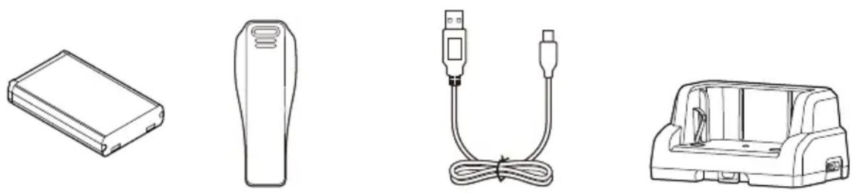
USB Bathey pack Belt clip Charging cradle
(USB Type-A/USB Type-C)
NOTE: Some accessories are not supplied, or the shape is different, depending on the transceiver version.
Icom and the Icom logo are registered trademarks of Icom Incorporated (Japan) in Japan, the United States, the United Kingdom, Germany, France, Spain, Russia, Australia, New Zealand, and/or other countries. All other products or brands are registered trademarks or trademarks of their respective holders.
■Precautions
⚠️DANGER! NEVER operate the transceiver near unshielded electrical blasting caps or in an explosive atmosphere. This could cause an explosion and death.
⚠ WARNING! NEVER use or charge Icom battery packs with non-Icom transceivers or non-Icom chargers. Only Icom battery packs are tested and approved for use with Icom transceivers or charged with Icom chargers. Using third-party or counterfeit battery packs or chargers may cause smoke, fire, or cause the battery to burst.
⚠ WARNING! NEVER hold the transceiver so that the antenna is very close to, or touching exposed parts of the body, especially the face or eyes, while transmitting.
⚠ WARNING! NEVER operate or touch the transceiver with wet hands. This could cause an electric shock or damage the transceiver.
⚠ WARNING! NEVER operate the transceiver with earphones, a headset or other audio accessories at high volume levels. The continuous high volume operation may cause a ringing in your ears. If you experience the ringing, reduce a volume level or discontinue use.
CAUTION: DO NOT use or leave the transceiver in excessively dusty environments. This could damage the transceiver.
CAUTION: DO NOT short the terminals of the battery pack. Shorting may occur if the terminals touch metal objects such as a key, so be careful when placing the battery packs (or the transceiver) in bags, and so on. Carry them so that shorting cannot occur with metal objects. Shorting may damage not only the battery pack, but also the transceiver.
CAUTION: DO NOT change the internal settings of the equipment. This may reduce equipment performance and/or cause extensive and expensive damage to the equipment.
The equipment warranty does not cover any problems caused by unauthorized internal adjustments.
CAUTION: DO NOT operate the transceiver unless the rear cover and the connector covers are securely attached to the transceiver and that the battery pack are dry before attachment.
Exposing the inside of the transceiver to dust or water will result in serious damage to the transceiver.
CAUTION: DO NOT operate the transceiver while driving a vehicle. Safe driving requires your full attention—anything less may result in an accident.
CAUTION: DO NOT use harsh solvents such as Benzine or alcohol when cleaning. This could damage the equipment surfaces. If the surface becomes dusty or dirty, wipe it clean with a soft, dry cloth.
CAUTION: DO NOT use the non-specified-microphone. Other microphones have different pin assignments and may damage the transceiver.
CAUTION: Confirm that all connectors and jacks are dry and clean before attachment. Exposing them to dust or water will result in serious damage to the transceiver.
■Precautions
NOTE: DO NOT use or leave the transceiver in areas with temperatures below -20^ or above +60^ , or in areas subject to direct sunlight, such as the dashboard.
DO NOT push [PTT] unless you actually intend to transmit.
NEVER place the transceiver in an insecure place to avoid inadvertent use by unauthorized persons.
Even when the transceiver power is OFF, a slight current still flows in the circuits. Remove the battery pack from the transceiver when not using it for a long time. Otherwise, the installed battery pack will become exhausted, and will need to be recharged or replaced.
KEEP the transceiver away from heavy rain, and never immerse it in water. The transceiver meets IP54* requirements for dust-protection and splash resistance. However, once the transceiver has been dropped, or the waterproof seal is cracked or damaged, dust-protection and splash resistance cannot be guaranteed due to the fact that the transceiver may be cracked or the waterproof seal damaged, and so on.
* Only when the rear cover and the connector covers are attached.
NOTE: When an optional product with a lower IP rating than the transceiver is attached, the transceiver meets the lower IP rating of the optional product.
■About CE and DOC
CE
Hereby, Icom Inc. declares that the versions of IC-U20SR which have the "CE" symbol on
the product, comply with the essential requirements of the Radio Equipment Directive, 2014/53/EU, and the restriction of the use of certain hazardous substances in electrical and electronic equipment Directive, 2011/65/EU. The full text of the EU declaration of conformity is available at the following internet address: https://www.icomjapan.com/support/
■Disposal

The crossed-out wheeled-bin symbol on your product, literature, or packaging reminds you that in the European Union, all electrical and electronic
products, batteries, and accumulators (rechargeable batteries) must be taken to designated collection locations at the end of their working life. Do not dispose of these products as unsorted municipal waste. Dispose of them according to the laws in your area.
■About UKCA DOC
To obtain the UKCA Declaration of Conformity, please contact Icom UK Limited by email at info@icomuk.co.uk or alternatively call + 44(0) 1227 741741.
Icom is not responsible for the destruction, damage to, or performance of any Icom or non-Icom equipment, if the malfunction is because of:
- Force majeure, including, but not limited to, fires, earthquakes, storms, floods, lightning, other natural disasters, disturbances, riots, war, or radioactive contamination.
- The use of Icom transceivers with any equipment that is not manufactured or approved by Icom.
Table of contents
■ Important....1
■ Explicit definitions.... 1
■ About weld lines....1
■ Supplied accessories....1
■ Precautions 2
■ About CE and DOC.... 3
■ Disposal 3
■ About UKCA DOC....3
1 PREPARATION......5
2 PANEL DESCRIPTION....6
■ Front, top and side panels....6
■ Function display .... 7
3 BATTERY CHARGING 8
■ Battery cautions 8
■ Charging cautions 9
■ Battery charging.... 10
4 BASIC OPERATION....12
■ Turning the transceiver ON or OFF 12
■ Selecting a channel.... 12
■ Receiving and Transmitting.... 12
■ Key Lock function.... 12
■ Call-Ring operation 12
■ Smart-Ring operation.... 13
■ Set mode operation.... 13
5 OPTIONS....14
6 CHANNEL FREQUENCY LIST AND TECHNICAL INFORMATION....15
1
PREPARATION
◇Battery pack
NOTE: Before detaching or attaching a battery pack, BE SURE to turn OFF the transceiver by holding down [⏻] for 1 second. Otherwise, a transceiver malfunction could occur.
- Release the rear cover lock clip (①) and remove the rear cover (②).
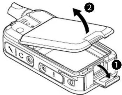
- Install the supplied battery pack so that the terminals of the battery pack and the transceiver meet.
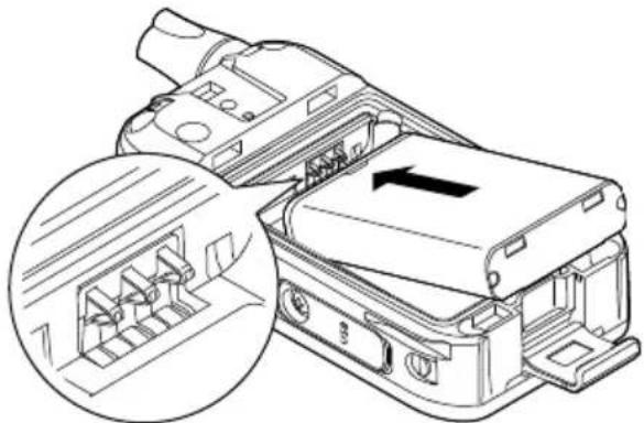
natural_image
Technical line drawing of a mechanical component with an inset showing internal structure (no text or symbols)- Replace the rear cover (①) and the rear cover lock clip (②).

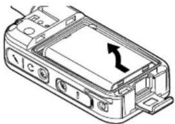
TIP: To remove the battery pack, slide the battery pack and lift it up in the direction of the arrow.
natural_image
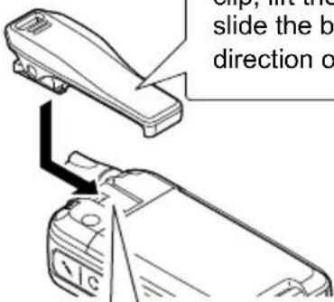
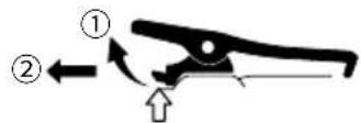
Technical line drawing of a device casing with an arrow indicating direction (no text or symbols present)◇Belt clip
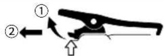
When removing the belt clip, lift the tab up ①, and slide the belt clip in the direction of the arrow ②.
Slide the belt clip in the direction of the arrow until the belt clip locks in place, and makes a 'click' sound.
BE CAREFUL! DO NOT break your fingernail.
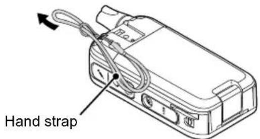
TIP: When attaching a hand strap (User supplied)
PANEL DESCRIPTION
■Front, top and side panels
![Antenna [Top]* Speaker 1 Microphone [Side]* Function display 2 3 5 6 7 8](/content/2026/04/726825/images/964db0955fb9bbce8f5e42e90853b904c552dae68a85859367ef12bb16d3d627.jpg)
* The [Side] and [Top] key functions are dealer assignable.
① [PTT] SWITCH
Hold down to transmit, release to receive.
② [CH/SET] KEY
● On the Standby screen, push to ent
or exit the Channel Select mode.
- On the Standby screen, hold down for 1 second to enter the Set mode.
On the Standby screen, hold down for r1 second to turn the Lock function ON or OFF.
- In the Set mode, push to move between the setting items, and hold down for 1 second to return to the Standby screen.
③ [+] KEY
Hold down for 1 second to turn the transceiver ON or OFF.
For only charging the battery.
The USB connector does not support USB Power Delivery (USB PD) or a data communication.
CAUTION: DO NOT use the transceiver without the connector covers or the optional equipment attached.
The transceiver meets IP54 requirements for dust-tight and splash resistance only when the connector covers or the optional HM-183LS is attached.
⑥ [MONI] KEY
While holding down this key, the Monitor function is ON on the Standby screen.
7 [no] KEY
⑧ [▲]/[▼] KEY
● On the Standby screen, push to adjust the audio level.
- In the Set mode and the Channel Select mode, push to select a value.
2 PANEL DESCRIPTION
Factory default key assignment
| [Side] | ● Push to make a Smart-Ring call. ● Hold down to make a Call-Ring call. |
| [Top] | ● Hold down for 2 seconds to enter the Emergency mode. ● Hold down for 1 second to exit the Emergency mode. NOTE: If a user holds down [Emergency] for the Emer SW OFF Timer set time before the Reminder Timer expires, the Emergency mode is canceled. |
■Function display
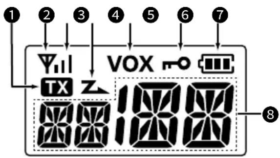
① TX ICON TX
Displayed while transmitting.
② ANTENNA ICON
● Displayed while the channel is busy (receiving).
- Blinks while the monitor function is turned ON.
③ SIGNAL STRENGTH INDICATOR
Displays the relative receive signal strength level.
4 SCAN ICON Z
● Displayed when the channel is selected as a scan target channel.
- Blinks while scanning.
⑤ VOX ICON VOX
Displayed when the VOX function is ON.
⑥ KEY LOCK ICON
Displayed when the Key Lock function is ON.
⑦ BATTERY INDICATOR
- Blinks while charging.
● Displays the remaining battery charge.
| Indication | ||||
| Battery Status | Full | Mid | Charging required | Battery exhausted |
* Blinks when the battery charge decreases to a set level.
⑧ ALPHANUMERIC READOUT
Displays messages such as channel number.
CAUTION: DO NOT use the transceiver without the connector covers or the optional equipment attached.
The transceiver meets IP54 requirements for dust-tight and splash resistance only when the connector covers or the optional HM-183LS is attached.
BATTERY CHARGING
■Battery cautions
Misuse of Li-ion batteries may result in the following hazards: smoke, fire, or the battery may rupture. Misuse can also cause damage to the battery or degradation of battery performance.
⚠️DANGER! NEVER incinerate used battery packs. Internal battery gas may cause an explosion.
⚠️DANGER! NEVER solder the battery terminals, or NEVER modify the battery pack. This may cause heat generation, and the battery may burst, emit smoke or catch fire.
⚠️DANGER! NEVER leave battery packs in places with temperatures above 60°C. High temperature buildup in the battery cells, such as could occur near fires or stoves, inside a sun-heated vehicle, or in direct sunlight for long periods of time may cause the battery cells to rupture or catch fire. Excessive temperatures may also degrade the battery pack's performance or shorten the battery cell's life.
⚠️DANGER! NEVER strike or otherwise impact the battery pack. Do not use the battery pack if it has been severely impacted or dropped, or if the pack has been subjected to heavy pressure. Battery pack damage may not be visible on the outside of the case. Even if the surface of the battery does not show cracks or any other damage, the cells inside the battery may rupture or catch fire.
⚠️DANGER! NEVER place battery packs near a fire. Fire or heat may cause them to rupture or explode. Dispose of used battery packs in accordance with local regulations.
⚠️DANGER! NEVER let fluid from inside the battery get in your eyes. This can cause blindness. Rinse your eyes with clean water, without rubbing them, and immediately go to a doctor.
⚠ WARNING! NEVER let fluid from inside the battery cells come in contact with your body. If it does, immediately wash with clean water.
⚠ WARNING! NEVER put the battery pack in a microwave oven, high-pressure container, or in an induction heating cooker. This could cause a fire, overheating, or cause the battery cells to rupture.
⚠ WARNING! NEVER use deteriorated battery packs. They could cause a fire.
CAUTION: DO NOT continue to use the battery pack if it emits an abnormal odor, heats up, or is discolored or deformed. If any of these conditions occur, contact your lcom dealer or distributor.
CAUTION: DO NOT expose the battery pack to rain, snow, saltwater, or any other liquids. Do not charge or use a wet pack. If the pack gets wet, be sure to wipe it with a clean dry cloth before using.
CAUTION: DO NOT use the battery pack out of the specified temperature range for the transceiver ( -20^ +60^ ). Using the battery out of its specified temperature range will reduce its performance and battery cell's life.
CAUTION: DO NOT leave the pack fully charged, completely discharged, or in an excessive temperature environment (above 50°C) for an extended period of time. If the battery pack must be left unused for a long time, it must be detached from the transceiver after discharging. You may use the battery pack until the remaining capacity is about half, then keep it safely in a cool and dry place at the following temperature range:
-20^ +50^ (within a month)
-20^ +40^ (within three months)
-20^ +20^ (within a year)
3 BATTERY CHARGING
■Battery cautions
BE SURE to replace the battery pack with a new one approximately five years after manufacturing, even if it still holds a charge. The material inside the battery cells will become weak after a period of time, even with little use. The estimated number of times you can charge the pack is between 300 and 500. Even when the pack appears to be fully charged, the operating time of the transceiver may become short when:
- Approximately 5 years have passed since the pack was manufactured.
- The pack has been repeatedly charged.
The battery cells may deteriorate and swell due to their characteristics if used in an environment and conditions such as: frequently charged, recharged immediately after full charge, used or saved in a hot place, or charged by methods other than the instructions. If the battery pack swells, it has reached the end of its life due to deterioration. Replace it with a brand new one.
■Charging cautions
⚠️DANGER! NEVER charge the battery pack in areas with extremely high temperatures, such as near fires or stoves, inside a sun-heated vehicle, or in direct sunlight. In such environments, the safety/protection circuit in the battery will activate, causing the battery to stop charging.
⚠ WARNING! NEVER charge the transceiver during a lightning storm. It may result in an electric shock, cause a fire or damage the transceiver. Always disconnect the AC adapter before a storm.
⚠ WARNING! NEVER charge or leave the battery in the battery charger beyond the specified time for charging. If the battery is not completely charged by the specified time, stop charging and remove the battery from the battery charger. Continuing to charge the battery beyond the specified time limit may cause a fire, overheating, or the battery may rupture.
⚠ WARNING! Occasionally observe the battery pack condition while charging. If any abnormal condition occurs, discontinue using the battery pack.
CAUTION: DO NOT insert the transceiver (battery attached to the transceiver) into the charger if it is wet or soiled. This could corrode the battery charger terminals or damage the charger. The charger is not waterproof.
NOTE: DO NOT charge the battery pack outside of the specified temperature range: 15^ C \~ 40^ C. Otherwise, the charging time will be longer, but the battery will not reach a full charge. While charging, at a point after the temperature goes out of the specified range, the charging will automatically stop.
■Battery charging
- Fully charge the transceiver before using it for the first time, or if it has not been used for more than 2 months. The charger automatically restarts charging when the battery voltage drops.
- Disconnect the AC adapter from the outlet when not charging the battery.
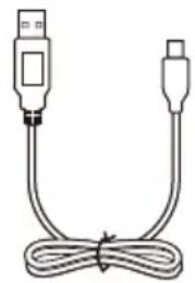
- Use the supplied USB cable.
- The battery icon on the function display blinks while charging and lights when the charging has been completed.
NOTE for charging with a USB cable:
- Use a 5 V/1 A output AC adapter.
- USB Power Delivery (USB PD) is not supported.
- The charging time may differ, depending on the current. When you use a lower than 1 A output AC adapter or PC, it may take longer to charge, or the battery may not be charged.
- Before using the AC adapter, thoroughly read its instructions.
NOTE: If "Q ER" is displayed, a charging error has occurred.
- Disconnect the USB cable or AC adapter, and then connect properly.
- Properly install the battery pack to the transceiver.
- Properly insert the transceiver into the charging cradle.
- Charge the battery pack within the specified temperature range: 15^ 40^ .
◇Charging directly
Connect the supplied USB cable to the [USB] connector.
Charging time:
Approximately 5.5 hours with 5 V/1 A input
![To an AC adapter or a PC (User supplied) USB Type-C USB cable To the [USB] connector Turn OFF](/content/2026/04/726825/images/9d4b1d43c291a04f8640ba245ea716253d4dfdfe0125913fec19fa544e5ba24c.jpg)
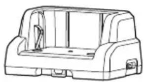
◇Charging on the cradle
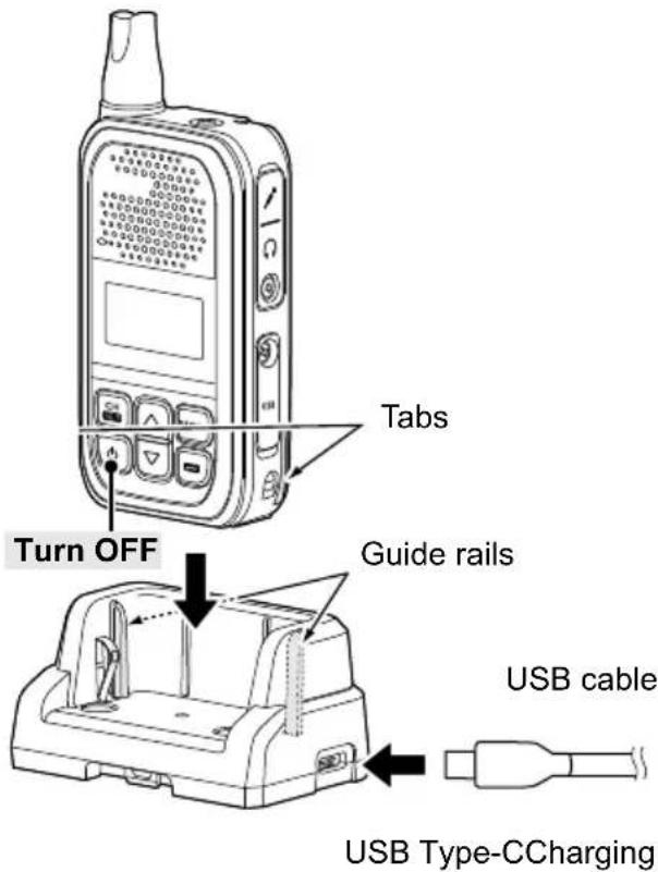
NOTE: Be sure the tabs on the transceiver are correctly aligned with the guide rails inside the cradle.
3 BATTERY CHARGING
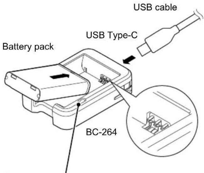
◇Rapidly charging the battery pack
You can charge the battery pack with the optional BC-264 BATTERY CHARGER.
Install the supplied battery pack so that the terminals of the battery pack and the battery charger meet.
① The battery pack can be charged by the charging cradle with the BC-262 inserted.
Charging time:
Approximately 3.8 hours with 5 V/1 A input
NOTE: Charging time will be longer in extremely hot or cold environments. We recommend charging between 15°C \~ 40°C.
Charging indicator
• Lights orange: Charging
- Not lit: Battery not installed or charging completed
NOTE for charging with a USB cable:
- Use a 5 V/1 A output AC adapter.
- USB Power Delivery (USB PD) is not supported.
- The charging time may differ, depending on the current. When you use a lower than 1 A output AC adapter or PC, it may take longer to charge, or the battery may not be charged.
- Before using the AC adapter, thoroughly read its instructions.
■Turning the transceiver ON or OFF
NOTE: Before using the transceiver for the first time, the battery pack must be fully charged for optimum life and operation. See the BATTERY CHARGING section.
- Hold down][for 1 second to turn the transceiver ON or OFF.
■Selecting a channel
- On the Standby screen, push [CH/SET].
- Enters the Channel Select mode and the channel number blinks.
- Push [▲] or [▼] to select a channel, and then push [CH/SET] to apply the setting.
- Returns to the Standby screen.
■Receiving and Transmitting
Receiving:
When a call is received, the antenna icon is displayed.
- Push [▲] or [▼] to adjust the audio output level to a comfortable listening level.
① The volume can be adjusted between 0 and 32.
Transmitting:
● While holding down [PTT], speak at your normal voice level.
- The TX icon is displayed while [PTT] is held down.
IMPORTANT:
To maximize the readability of your signal:
- After pushing [PTT], pause briefly before you start speaking.
- Hold the microphone 5 \~ 10 cm from your mouth, then speak at your normal voice level.
■Key Lock function
You can use the Key Lock function to prevent accidental channel changes and unnecessary function access, depending on the presetting.
All assignable keys except the following are electronically locked: [MONI], [Volume Up], [Volume Down], [Emergency], [Surveillance], and [PTT].
You can also make or receive calls, or turn the transceiver ON or OFF, during the Key Lock function is ON.
- Hold down for 1 second to turn the Key Lock function ON or OFF.
- The "O" icon is displayed when the Key Lock function is ON.
■Call-Ring operation
This function sends the preset ringer to your group members.
- Hold down [S-Ring/C-Ring] for 1 second to send the preset ringer.
- The TX icon is displayed while [S-Ring/C-Ring] is held down.
- The ringer may sound while holding down [S-Ring/C-Ring], depending on the setting.
- The same ringer sounds from your group members' speakers.
NOTE: To use this function, the operating channel and CTCSS tone or DTCS code must be the same on all of your group's transceivers.
4
BASIC OPERATION
■Smart-Ring operation
This function can judge whether the other station is within range or out of range. A transceiver that receives a Smart-Ring call from another transceiver sounds the Ringer melody. Also, the called transceiver sends an acknowledgment signal back to calling transceiver.
The called transceivers automatically send an answer back call to your transceiver.
-
Push [S-Ring/C-Ring] to make a Smart-Ring call.
-
The TX con is displayed while [S-Ring/C-Ring] is held down.
- When an answer back call is received, the transceiver sounds the Ringer melody.
When no answer back call is received, the transceiver sounds three short failure beeps.
- Push any key to stop the Ringer melody.
- Push [PTT] to transmit, if necessary.
NOTE:
- To use this function, the operating channel and CTCSS tone must be the same on all of your group's transceivers.
- This function can be operated for channels which CTCSS tone is set for.
■Set mode operation
NOTE: The Set mode items contained in the transceiver may differ, depending on the transceiver version or presetting. Ask your dealer for details.
- On the Standby screen, hold down [CH/SET] for 1 second.
- Enters the Set mode.
- Push [CH/SET] several times to select a setting item, and then push [▲] or [▼] to select a value.
- Hold down [CH/SET] for 1 second to exit the Set mode.
- Returns to the Standby screen.
Set mode items:
| ITEM FUNCTION | |
| BL Backlight | |
| BE Beep | |
| BV Beep | Level |
| RV | Ringer Level |
| AN | Announce |
| SQ SQL | Level |
| MG Mic Gain | |
| VX VOX | |
| VG VOX | Gain |
| CR Call-Ring Pattern | |
| SR Smart-Ring Pattern | |
◇Battery pack
• BP-304A Li-ion BATTERY PACK
3.6 V, 2200 mAh (minimum), 2350 mAh (typical)
Battery life*: 21 hours
* When the power save function is turned ON, and the operating periods are calculated under the following conditions:
TX:RX:standby = 5:5:90
◇Belt Clip
- MB-127 BELT CLIP
◇Chargers
• BC-262 BATTERY CHARGING CRADLE
• BC-264 BATTERY CHARGER
◇Speaker-Microphones
◇Earphone microphones and Headsets
• HM-153LS, HM-166LS EARPHONE MICROPHONE
• HS-94 HEADSET (Ear hook type)
• HS-95HEADSET (Neck and arm type)
• HS-97HEADSET (Throat microphone)
◇Others
• OPC-2006LS PLUG ADAPTER CABLE
L-type plug conversion cable
Connects the HS-94/HS-95/HS-97 to the transceiver for the VOX operation.
• OPC-2328PTT SWITCH CABLE
L-type headset adapter cable with PTT switch
Connects the HS-94/HS-95/HS-97 to the transceiver.
• OPC-2144 PLUG ADAPTER CABLE
L-type plug conversion cable
Connects the optional speaker microphone, earphone microphone, or headset to the transceiver.
NOTE: BE SURE to turn OFF the transceiver before connecting or disconnecting an optional equipment.
① Some options may not be available in some countries. Ask your dealer for details.
CHANNEL FREQUENCY LIST AND TECHNICAL INFORMATION
Channel List
| Channel Frequency (MHz) C.Tone* | ||
| 1 | 446.006250 | 97.4 |
| 2 | 446.018750 | 100.0 |
| 3 | 446.031250 | 103.5 |
| 4 | 446.043750 | 107.2 |
| 5 | 446.056250 | 110.9 |
| 6 | 446.068750 | 114.8 |
| 7 | 446.081250 | 118.8 |
| 8 | 446.093750 | 123.0 |
| 9 | 446.106250 | 127.3 |
| 10 | 446.118750 | 131.8 |
| 11 | 446.131250 | 136.5 |
| 12 | 446.143750 | 141.3 |
| 13 | 446.156250 | 146.2 |
| 14 | 446.168750 | 151.4 |
| 15 | 446.181250 | 156.7 |
| 16 | 446.193750 | 159.8 |
* CTCSS tone or DTCS code can be manually programmed. Ask your dealer for details.
Technical Information
| Frequency coverage 446.006250 ~ 446.193 | 750 MHz (PMR446) |
| Output power 0.5 W | |
| Dimensions (projections not included) 50.0 (W) × 94.0 (H) × 26.7 (D) mm | |
| SAR 10g Estimation 1.46 W/kg | |
| Weight (approximate) 157 g (with BP-304A) | 168 g (with MB-127, BP-304A) |
① All stated specifications are typical and subject to change without notice or obligation.
natural_image
Line drawing of a USB cable with two connectors (no text or symbols)natural_image
Line drawing of a vehicle rear bumper with no text or symbolsLadestation
natural_image
Technical illustration of a mechanical component with an inset close-up showing internal structure (no text or symbols)natural_image
Technical line drawing of a device casing with an arrow indicating direction (no text or symbols present)◇Gürtelclip

natural_image
Technical line drawing of a mechanical component with an inset close-up showing internal structure (no text or symbols)natural_image
Line drawing of a mobile phone casing with an arrow indicating direction (no text or symbols)◇Pinza de cinturón


The Ground Truth image displays a single, solid horizontal line. According to Rule 2 (UNDERSCORE & LINE RULES), this is a stylistic or background line, not a placeholder underscore. Therefore, the OCR result must ignore it and output nothing or only meaningful text. The provided OCR content is "____", which consists of four underscores. This is an incorrect interpretation of the line as a placeholder, violating the rule that stylistic lines must be ignored. The OCR has hallucinated underscores where none should exist based on the GT's visual context. Hence, the OCR result is inconsistent with the Ground Truth.
natural_image
Technical line drawing of a mechanical component with an inset close-up showing internal structure (no text or symbols)natural_image
Technical line drawing of a device casing with an arrow indicating a directional flow (no text or symbols present)◇Clip de ceinture
natural_image
Diagram showing a device being processed from a tray, with no visible text or symbolsnatural_image
Isometric line drawing of a rectangular electronic component or housing (no text or symbols)Pacco batterie

Clip da cintura
natural_image
Line drawing of a USB cable with two connectors (no text or symbols)(USB tipo-A/USB tipo-C)
natural_image
Line drawing of a vehicle chassis frame (no text or symbols)natural_image
Technical illustration of an electrical connector with internal structure and a magnified inset showing internal components (no text or symbols)natural_image
Technical line drawing of a device casing with an arrow indicating direction (no text or symbols present)◇Clip da cintura

TX:RX:standby = 5:5:90
◇Clip da cintura
• MB-127 CLIP DA CINTURA
◇Caricabatterie
• BC-262 BASE DI CARICA BATTERIA
• BC-264 CARICABATTERIA
◇Altoparlante - Microfoni
• HM-183LS MICROFONO ALTOPARLANTE
• HM-186LS MICROFONO ALTOPARLANTE
natural_image
Technical line drawing of a mechanical component with an inset close-up showing internal structure (no text or symbols)natural_image
Technical line drawing of a device casing with an arrow indicating direction (no text or symbols)◇Riemclip

③ SIGNAALSTERKTE-INDICATOR
How the World Communicates

natural_image
Blank white image with a black bottom bar at the bottom (no text or symbols)- ■Important
- ■Explicit definitions
- ■About weld lines
- ■ Supplied accessories
- ■Precautions
- ■About CE and DOC
- CE
- ■Disposal
- ■About UKCA DOC
- Table of contents
- 1
- PREPARATION
- ◇Battery pack
- ◇Belt clip
- PANEL DESCRIPTION
- ■Front, top and side panels
- ① [PTT] SWITCH
- ② [CH/SET] KEY
- ③ [+] KEY
- ⑥ [MONI] KEY
- [no] KEY
- ⑧ [▲]/[▼] KEY
- PANEL DESCRIPTION
- ■Function display
- ① TX ICON TX
- ② ANTENNA ICON
- ③ SIGNAL STRENGTH INDICATOR
- SCAN ICON Z
- ⑤ VOX ICON VOX
- ⑥ KEY LOCK ICON
- ⑦ BATTERY INDICATOR
- ⑧ ALPHANUMERIC READOUT
- BATTERY CHARGING
- ■Battery cautions
- BATTERY CHARGING
- ■Charging cautions
- ■Battery charging
- NOTE for charging with a USB cable:
- ◇Charging directly
- ◇Rapidly charging the battery pack
- ■Turning the transceiver ON or OFF
- ■Selecting a channel
- ■Receiving and Transmitting
- Receiving:
- Transmitting:
- IMPORTANT:
- ■Key Lock function
- ■Call-Ring operation
- 4
- BASIC OPERATION
- ■Smart-Ring operation
- NOTE:
- ■Set mode operation
- ◇Chargers
- ◇Speaker-Microphones
- ◇Earphone microphones and Headsets
- ◇Others
- CHANNEL FREQUENCY LIST AND TECHNICAL INFORMATION
- ◇Gürtelclip
- ◇Pinza de cinturón
- ◇Clip de ceinture
- ◇Clip da cintura
- ◇Caricabatterie
- ◇Altoparlante - Microfoni
- ◇Riemclip
- ③ SIGNAALSTERKTE-INDICATOR
Brand : ICOM
Model : IC-U20SR
Category : Portable transceiver radio