97902 - Mobile electric sprayer Chapin - Free user manual and instructions
Find the device manual for free 97902 Chapin in PDF.

User questions about 97902 Chapin
0 question about this device. Answer the ones you know or ask your own.
Ask a new question about this device
Download the instructions for your Mobile electric sprayer in PDF format for free! Find your manual 97902 - Chapin and take your electronic device back in hand. On this page are published all the documents necessary for the use of your device. 97902 by Chapin.
USER MANUAL 97902 Chapin
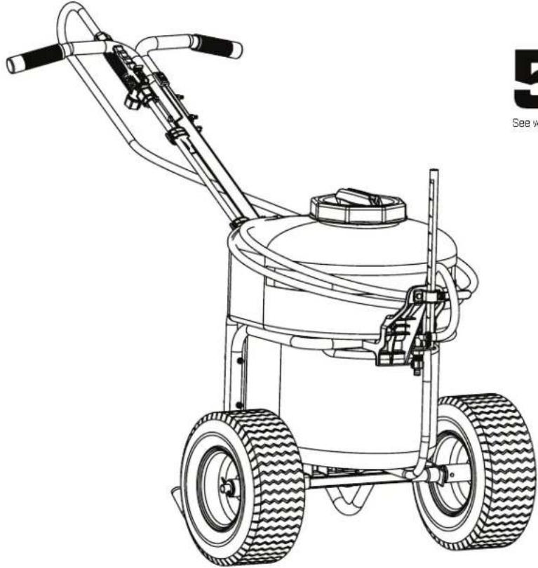
12 Gallon Battery-Operated Push Sprayer
USE AND CARE MANUAL
WARNING
CAREFULLY READ THESE INSTRUCTIONS BEFORE USE
Failure to do so may result in damage to property and/or person.
natural_image
Line drawing of a two-wheeled lawn mower with visible tire tracks and handle (no text or symbols)
See website for warranty details
Model 97902
CONGRATULATIONS!
YOU HAVE JUST PURCHASED A QUALITY CHAPIN PRODUCT.
BEFORE RETURNING THIS PRODUCT FOR ANY REASON, PLEASE CALL:
1-800-950-4458
When calling, please have the following information available: Sales receipt & model number. This number connects you directly with the manufacturer of this product. Our Technical Support Team will be happy to help you with any assembly, troubleshooting and replacement information you may need.
WARNING
WARNING: Improper use or failure to follow instructions can result in explosive failure causing serious eye or other injury. For safe use of this product you must read and follow all instructions. Do not leave a pressurized sprayer in the hot sun. Heat can cause pressure build-up resulting in possible explosion. Do not store or leave solution in tank after use. Always wear goggles, gloves, long sleeve shirt, long pants and full foot protection when spraying. Do not attempt to modify this sprayer. Replace parts only with manufacturer's original parts. Never spray flammable, caustic, acidic, chlorine, bleach or other corrosive solutions or heat, pressure, or gas producing chemicals. Always read and follow chemical manufacturer's instructions before use with this sprayer as some chemicals may be hazardous when used with this sprayer.
CAUTION
- PRE-USE CHECK: Before each use check tightness of hose nut to be sure hose is securely attached to the shut-off assembly. Ensure that all nozzle and wand connections are tight.
- Do Not exceed a tank solution temperature of 120^ / 49^ .
NOTE: The tank and hose may have residual water in it due to quality testing performed on the sprayer.
WARNING
This sprayer is designed to operate with a Chapin 24V Lithium Ion battery ONLY. Any other batteries could cause serious harm or injury to the operator and serious damage to the sprayer.
WARNING: For safe operation, read this manual before using the charger. The battery pack is not fully charged out of the carton. Before using the battery pack and charger, read the safety instructions below. Then follow charging procedures outlined.
NOTE: Remove battery and place in charger when not in use.
IMPORTANT SAFETY INSTRUCTION FOR BATTERY PACKS READ ALL INSTRUCTIONS
- DO NOT incinerate the battery pack even if it is severely damaged or is completely worn out. The battery pack can explode in a fire. Toxic fumes and materials are created when battery packs are burned.
- DO NOT charge or use battery in explosive atmospheres, such as in the presence of flammable liquids, gases or dust. Inserting or removing the battery from the charger may ignite the dust or fumes.
- If battery contents come into contact with the skin, immediately wash area with mild soap and water. If battery liquid gets into the eye, rinse water over the open eye for 15 minutes or until irritation ceases. If medical attention is needed, the battery electrolyte for Lithium-Ion batteries is composed of a mixture of liquid organic carbonates and lithium salts.
- Contents of opened battery cells may cause respiratory irritation. Provide fresh air. If symptoms persist, seek medical attention. WARNING: Burn hazard. Battery liquid may be flammable if exposed to spark or flame.
- Charge the battery packs only in Chapin chargers.
- DO NOT splash or immerse in water or other liquids. This may cause premature cell failure.
- DO NOT store or use the tool and battery pack in locations where the temperature may reach or exceed 105^ [40°C] (such as outside sheds or metal buildings in summer).
WARNING: Never attempt to open the battery pack for any reason. If battery pack case is cracked or damaged, do not insert into charger. Do not crush, drop or damage battery pack. Do not use a battery pack or charger that has received a sharp blow, been dropped, run over or damaged in any way (i.e., pierced with a nail, hit with a hammer, stepped on). Damaged battery packs should be returned to service center for recycling.
WARNING: Fire hazard. Do not store or carry battery so that metal objects can contact exposed battery terminals. For example, do not place battery in aprons, pockets, tool boxes, product kit boxes, drawers, etc., with loose nails, screws, keys, etc.
Transporting batteries can possibly cause fires if the battery terminals inadvertently come in contact with conductive materials such as keys, coins, hand tools and the like. The US Department of transportation Hazardous Material Regulations (HMR) actually prohibit transporting batteries in commerce or on airplanes (i.e., packed in suitcases and carry-on luggage) UNLESS they are properly protected from short circuits. So when transporting individual batteries, make sure that the battery terminals are protected and well insulated from materials that could contact them and cause a short circuit. NOTE: Lithium-Ion batteries should not be put in checked baggage.
STORAGE RECOMMENDATIONS
- The best storage place is one that is cool and dry away from direct sunlight and excess heat or cold.
- Long storage will not harm the battery pack or charger.
CHARGING PROCEDURE
Chapin chargers are designed to charge Chapin battery packs in 3.5-4 hours depending on the pack being charged.
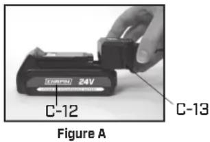
- Plug the charger (C-13) into an appropriate outlet before inserting the battery pack.
- Insert the battery pack (C-12) into the charger as shown in figure A.
- The red light on the charger is continuously on when the battery is charging.
- The green light on the charger is continuously on when the battery is charged. The pack is fully charged and may be used at this time or left on the charger.
- Blinking red and green lights on the charger indicates a defective battery and should properly be disposed of.
text_image
C-12 Figure A C-13Battery Charge Indicator
When battery is disconnected from the charger, depress green button to see the charge level. To charge see "Charging Procedures" in this manual.
Recharge discharged batteries as soon as possible after use or battery life may be greatly diminished. For longest battery life, do not discharge batteries fully. It is recommended that the batteries be recharged after each use.

text_image
Red Needs Charge 1/4 Charge 1/2 Charge 3/4 Charge Green Check ButtonLEAVING THE BATTERY IN THE CHARGER
The charger and battery pack can be left connected with the green LED glowing indefinitely. The charger will keep the battery pack fresh and fully charged.
IMPORTANT CHARGING NOTES
- Longest life and best performance can be obtained if the battery pack is charged when the air temperature is between 65°F and 75°F (18°-24°C). DO NOT charge the battery pack in an air temperature below +40°F (+4.5°C), or above +105°F (+40.5°C). This is important and will prevent serious damage to the battery pack.
- The charger and battery pack may become warm to touch while charging. This is a normal condition, and does not indicate a problem. To facilitate the cooling of the battery pack after use, avoid placing the charger or battery pack in a warm environment such as in a metal shed, or an uninsulated trailer.
- If the battery pack does not charge properly:
a. Check current at receptacle by plugging in a lamp or other appliance.
b. Check to see if receptacle is connected to a light switch which turns power off when you turn out the lights.
c. Move charger and battery pack to a location where the surrounding air temperature is approximately 65°F and 75°F (18°-24°C). - The battery pack should be recharged when it fails to produce sufficient power on jobs which were easily done previously. DO NOT CONTINUE to use under these conditions. Follow the charging procedure. You may also charge a partially used pack whenever you desire with no adverse effect on the battery pack.
- Foreign materials of a conductive nature such as, but not limited to, steel wool, aluminum foil, or any buildup of metallic particles should be kept away from charger cavities. Always unplug the charger from the power supply when there is no battery pack in the cavity. Unplug charger before attempting to clean.
- Do not freeze or immerse charger in water or any other liquid.
WARNING: Shock hazard. Do not allow any liquid to get inside charger. Never attempt to open the battery pack for any reason. If the plastic housing of the battery pack breaks or cracks, call 1-800-822-8837 for recycling information.
INSTALLING AND REMOVING THE BATTERY PACK FROM THE SPRAYER
WARNING: Make sure switch is in the off position.
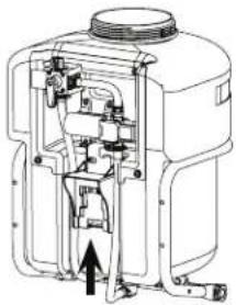
TO INSTALL BATTERY PACK: Insert battery pack into tool until an audible click is heard [Figure B]. Make sure battery pack is fully seated and latched into position.
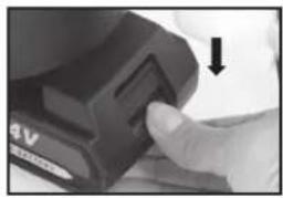
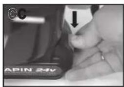
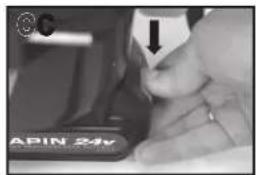
TO REMOVE THE BATTERY PACK: Depress the battery release button as shown in Figure C and pull battery pack out of tool.
natural_image
Technical line drawing of a mechanical device with internal components and an arrow indicating direction (no text or symbols)
natural_image
Close-up of a hand pressing a button on a black electronic device (no visible text or symbols)Figure B
IMPORTANT SAFETY INSTRUCTIONS FOR BATTERY CHARGERS
SAVE THESE INSTRUCTIONS: This manual contains important safety instructions for battery chargers.
- Before using charger, read all instructions and cautionary markings on charger, battery pack, and product using battery pack.
WARNING: Shock hazard. Do not allow any liquid to get inside charger.
CAUTION: Burn hazard. To reduce the risk of injury, charge only designated Chapin batteries. Other types of batteries my burst causing personal injury and damage.
CAUTION: Under certain conditions, with the charger plugged into the power supply, the charger can be shorted by foreign material. Foreign materials of a conductive nature such as, but not limited to, steel wool, aluminum foil, or any build up of metallic particles should be kept away from charger cavities. Always unplug the charger from the power supply when there is no battery pack in the cavity. Unplug charger before attempting to clean.
WARNING: DO NOT attempt to charge the battery pack with any chargers other than the ones in this manual. The charger and battery pack are specifically designed to work together.
• These chargers are not intended for any uses other than charging designated Chapin rechargeable batteries. Any other uses may result in risk of fire, electric shock or electrocution.
• DO NOT expose charger to rain or snow.
- Pull by plug rather than cord when disconnecting charger. This will reduce risk of damage to electric plug and cord.
• Make sure that cord is located so that it will not be stepped on, tripped over, or otherwise subjected to damage or stress.
- DO NOT use an extension cord unless it is absolutely necessary. Use of improper extension cord could result in risk of fire, electric shock, or electrocution.
- An extension cord must have adequate wire size [AWG or American Wire Gauge] for safety. The smaller the gauge number of the wire, the greater the capacity of the cable, that is 16 gauge has more capacity than 18 gauge. When using more than one extension to make up the total length, be sure each individual extension contains at least the minimum wire size.
- DO NOT operate charger with damaged cord or plug - have them replaced immediately.
- DO NOT operate charger if it has received a sharp blow, been dropped, or otherwise damaged in any way. Take it to an authorized service center.
- DO NOT disassemble charger; take it to an authorized service center when service or repair is required. Incorrect reassembly may result in a risk of electric shock electrocution or fire.
- Disconnect the charger from the outlet before attempting any cleaning. This will reduce the risk of electric shock. Removing the battery pack will not reduce the risk.
- NEVER attempt to connect 2 chargers together.
- The charger is designed to operate on standard household electrical power (120Volts). Do not attempt to use it on any other voltage.
Symbols The label on your tool may include the following symbols.
V.....volts
Hz hertz
min.minutes.....
____ ____ direct current
Class I Construction (grounded)
☐ Class II Construction (double insulated)
Read instruction manual before use
Use proper eye protection
A..... amperes
W..... watts
\~...... alternating current
no no load speed
earthing terminal
⚠️ ...... safety alert symbol
.../min or rpm revolutions or reciprocation per minute
Use proper respiratory protection
O Use proper hearing protection
Contents:
Contenu: Contenido:
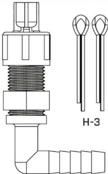
Sprayer Hardware [Actual size]
natural_image
Pure diagram of eight identical bolted components arranged in a row, no text or symbols presentH-1
natural_image
Technical line drawing of a mechanical component with two inset views labeled H-3 (no text or symbols on the diagram itself)H-2
text_image
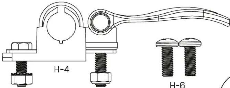
H-4 H-6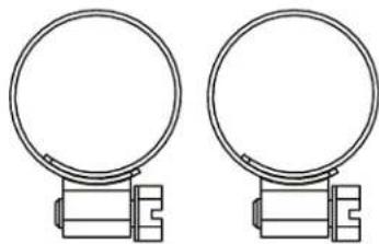
natural_image
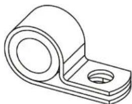
Two identical mechanical clamping components with circular and rectangular features (no text or symbols)H-5
natural_image
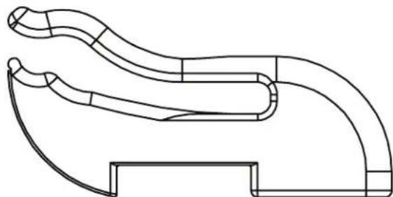
Technical line drawing of a mechanical component with curved and straight sections (no text or symbols)H-9 [X2]

natural_image
Two concentric circles diagram with no text or symbolsH-7[X2]
natural_image
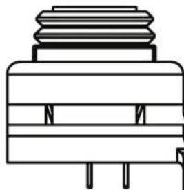
Isometric line drawing of a mechanical bracket component (no text or symbols)H-8
natural_image
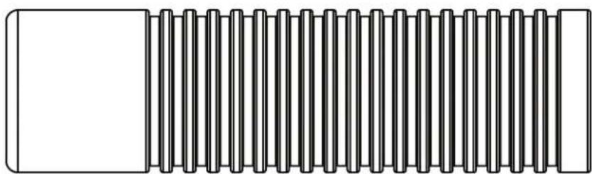
Pure technical line drawing of a mechanical component with no text or symbols
natural_image
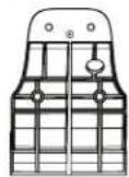
Simple line drawing of a rectangular frame with a circular hole at the center (no text or symbols)H-10
natural_image
Pure electrical circuit lines without any symbolsH-11 [X2]

H-12,[X2]
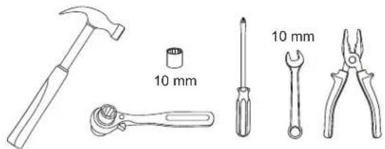
TOOLS NEEDED: HERRAMIENTAS REQUERIDAS: OUTILS REQUIS:
natural_image
Line drawings of five different tools: a hammer, screwdriver, wrench, pliers, and a cylindrical component (no text or symbols present)Sprayer Components [Not Actual size]
Componentes del pulverizador (no en tamaño real)
Composants de Pulvérisateur (taille non réelle)
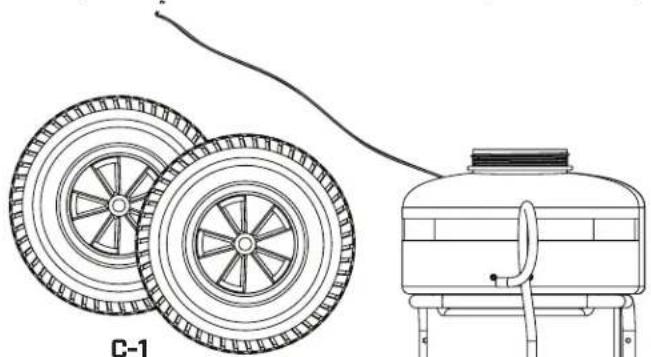
natural_image
Technical line drawing of a water heater system with two wheel wheels and a water tank (no text or symbols)C-1 Wheels Ruedas Roues

C-3
Axel Rod
Varilla del eje
Tige de l'axe

natural_image
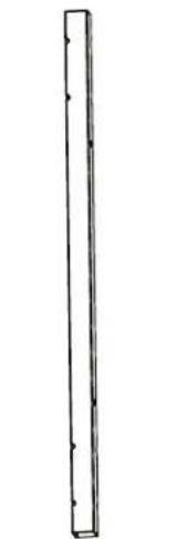
Simple line drawing of a vertical rectangular shape with evenly spaced dots along its edges (no text or symbols)C-5 Handle Bar Tubing Tubo del manillar Tube du guidon
natural_image
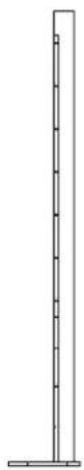
Simple line drawing of a vertical pole with evenly spaced tick marks (no text or symbols)C-6 Nozzle Bar Barra de la boquilla Tube porte-buses
natural_image
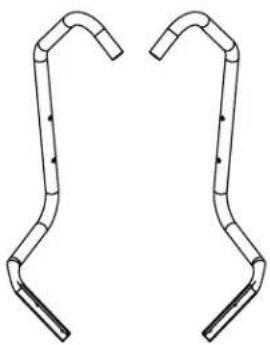
Pure line drawing of two symmetrical mechanical or architectural elements with curved ends and vertical supports (no text or symbols)C-8 Frame Leg Pata del chasis Pied du cadre
natural_image
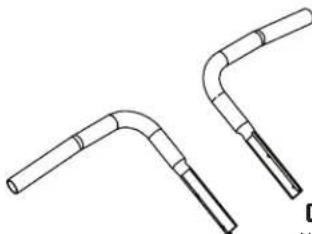
Pure line drawing of two bent pipe fittings (no text or symbols)C-9
Frame Leg
Pata del chasis
Pied du cadre
C-11
Handle Manija Poignée
C-4
On/off Switch Wiring Harness
(Attached to C-2)
Interruptor de encendido/apagado del
arnés de cableado [junto a C-2]
Faisceau de câcble de l'interrupteur de
marche/arrêt (joint à C-2)
C-7
Nozzle Bracket
Soporte de la boquilla
Support de buse
natural_image
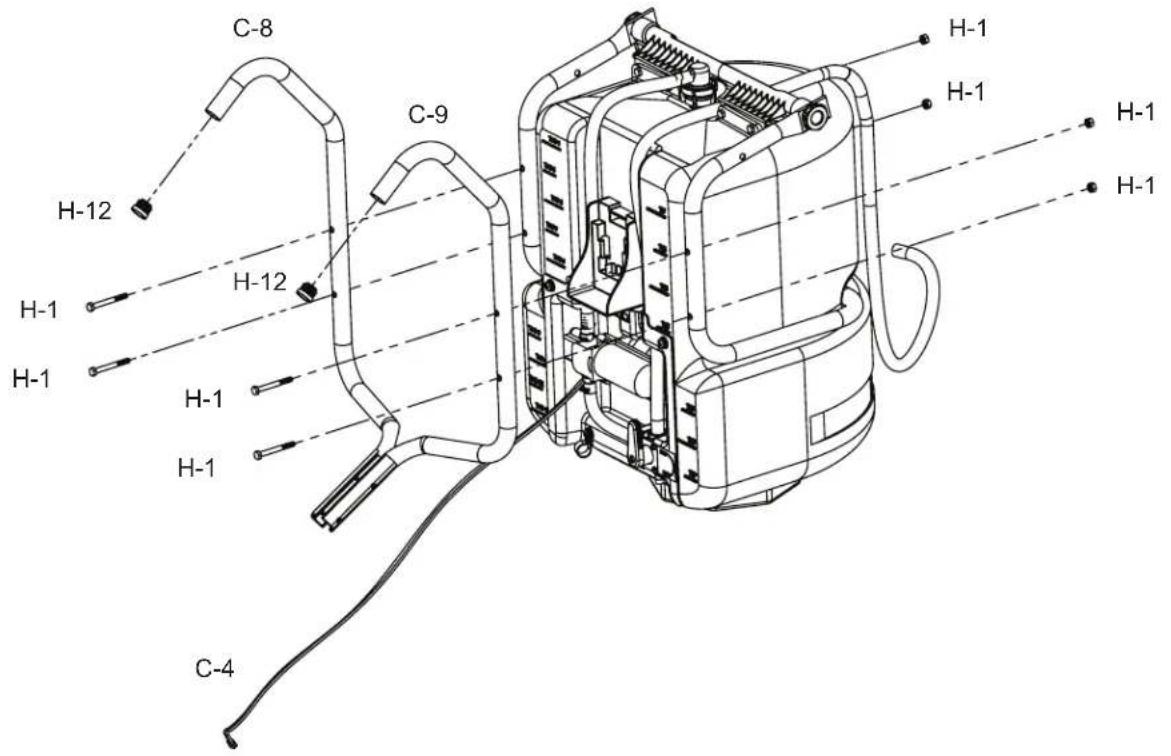
Pure mechanical pipe fitting diagram without any text, numbers, or symbolsAttach frame leg [C-8 and C-9] with nuts and bolts (H-1) to tank assembly [C-2]. Install end caps (H-12) into frame legs (C-8 and C-9).
text_image
C-8 H-12 H-1 H-1 H-1 H-1 C-9 H-1 H-1 H-1 H-1 H-1 C-4 H-1 H-1 H-12
HANDLE BAR INSTALLATION
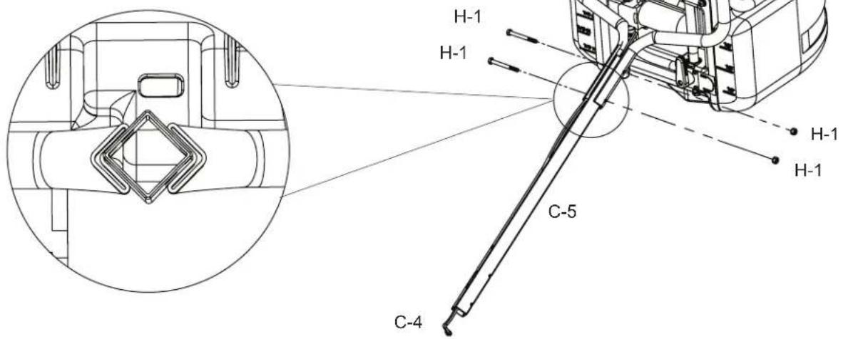
Run on/off switch wiring harness [C-4] through handle bar tubing [C-5]. Bolt handle bar to assembled frame legs using H-1 nuts and bolts.
text_image
H-1 H-1 C-5 C-4 H-1 H-12.1
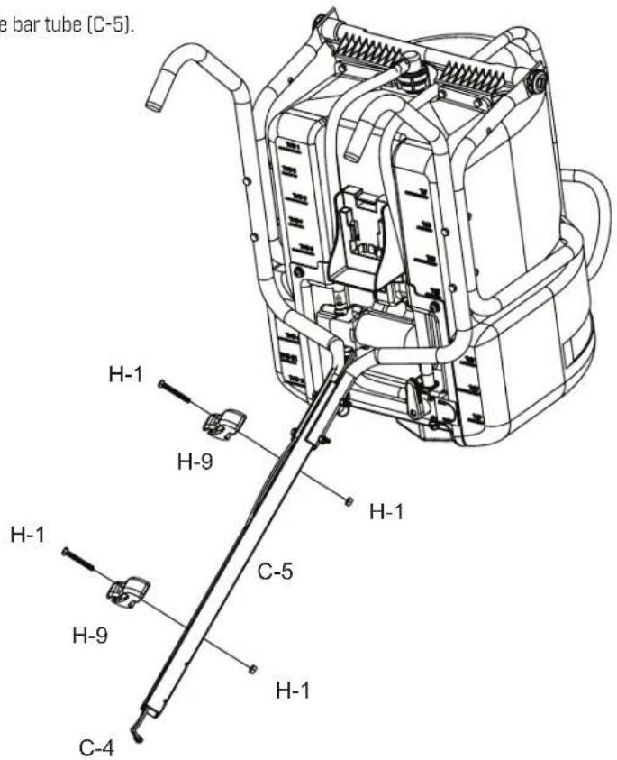
Bolt wand clips (H-9) to handle bar tube (C-5).
text_image
e bar tube (C-5). H-1 H-9 H-1 H-1 C-5 H-9 H-1 C-43
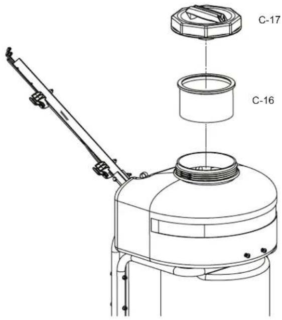
ASSEMBLE FILTER AND CAP
Insert Filter [C-16] and twist on cap [C-17].
text_image
C-17 C-164
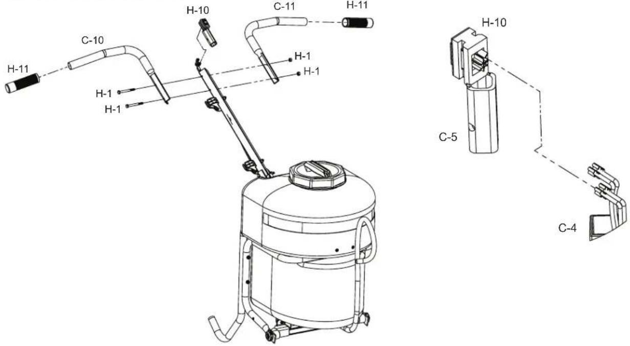
ASSEMBLE HANDLES AND ON/OFF SWITCH
Connect the on/off wiring harness(C-4) to switch and insert switch bracket (H-10) into square handle bar tubing (C-5). Bolt the right (C-10) and left handles (C-11) to the handle bar tubing using (H-1) bolts. Lastly, insert handle grips (H-11) onto handlebars (C-10 and C-11).
text_image
H-11 C-10 H-1 H-1 H-10 C-11 H-11 H-1 H-1 H-10 C-5 C-45
AXEL AND WHEEL INSTALLATION
Flip unit upside down for easy access. Insert axel rod (C-3) into axel bracket until centered; then fasten each wheel with washer (H-7) and cotter pin (H-3) using the outermost hole in axel. Bend each cotter pin to ensure a secure installation.

text_image
side down for easy access. od [C-3] into axel bracket until en fasten each wheel with ) and cotter pin [H-3] using st hole in axel. Bend each ensure a secure installation. Cotter Pin attaches on outside of each wheel H-7 C-1 C-1 H-7 C-3C-3 H-3 H-3 H-7 H-3 Bend H-78E
6
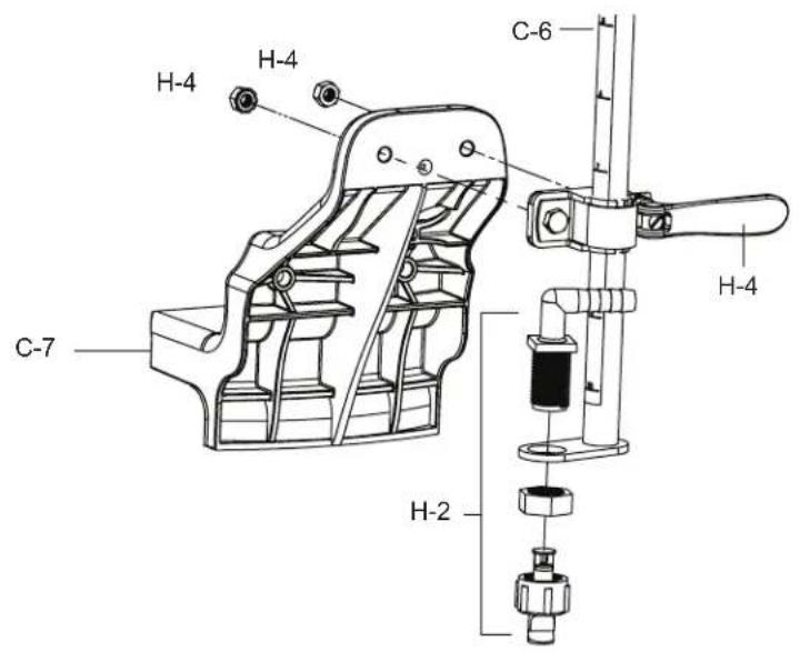
ASSEMBLE ADJUSTABLE NOZZLE BRACKET
Assemble cam lock bracket [H-4] with supplied nuts and bolts from [H-4] to nozzle bracket [C-7]. Then fasten nozzle assy [H-2] to nozzle bar [C-6] as shown.
text_image
H-4 H-4 C-7 C-6 H-4 H-2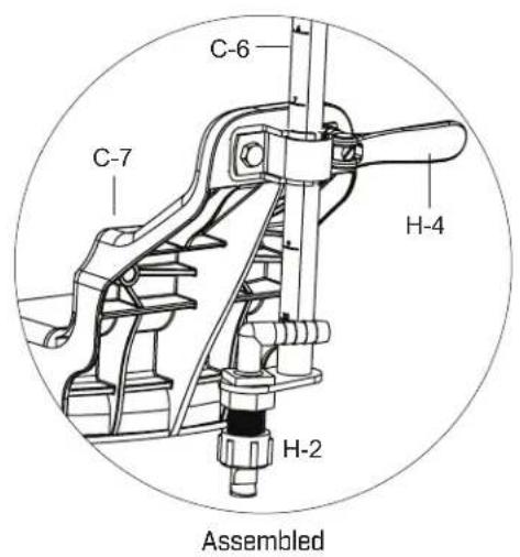
text_image
C-6 C-7 H-4 H-2 Assembled7
ATTACH NOZZLE BRACKET AND ADJUSTABLE NOZZLE TO TANK
Using supplied machine screws (H-6) fasten adjustable nozzle bracket assembly to tank. Assemble hose from tank (C-2) to nozzle assembly (H-2) with worm gear clamp (H-5).
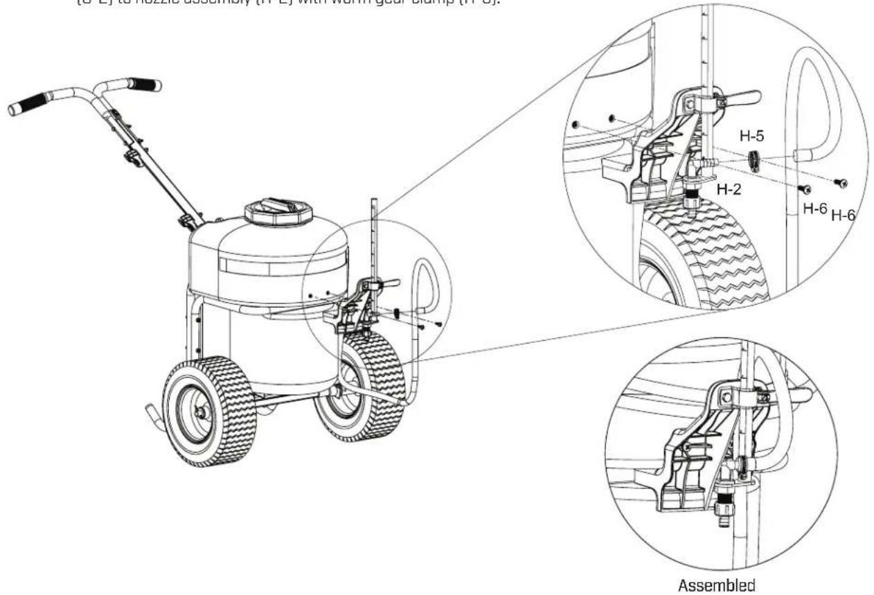
text_image
[S-E] to hobbles assembly [H-E] with worm gear clamp [H-G]. H-5 H-2 H-6 H-6 Assembled8
ASSEMBLE DISCHARGE TO DIVERTING VALVE
Connect discharge with hose [C-15] to diverting valve as shown. Thread hose through loop clamp (H-8)[Figure A]. Assemble worm gear clamp (H-5) to hose (Figure B). Assemble hose to diverting valve (Figure C). Tighten worm gear clamp and loop clamp.
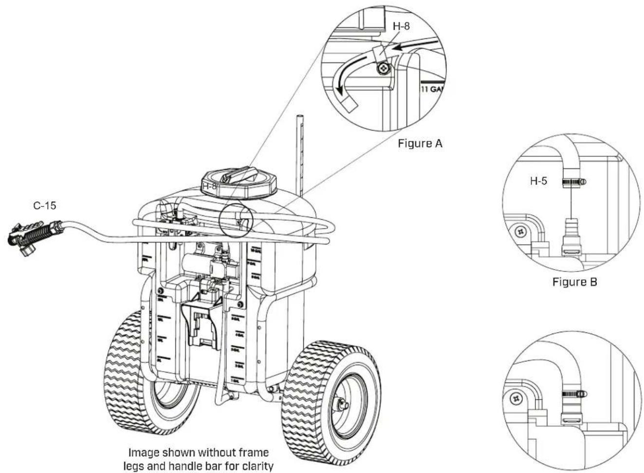
Figure C
9
ASSEMBLE WAND TO SHUT-OFF
Make sure the O-ring is installed on the end of the extension wand (C-14). Insert the wand into discharge with hose (C-15). Turn and tighten the retaining nut clock-wise onto the shut-off valve.
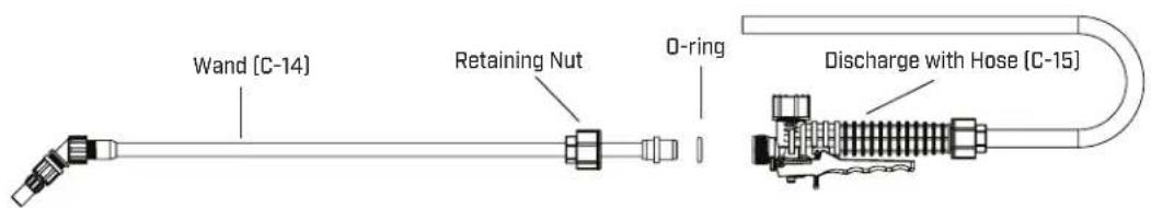
text_image
Wand [C-14] Retaining Nut O-ring Discharge with Hose [C-15]FILLING THE SPRAYER
Make sure the filter basket is in place to keep debris from entering the tank.
Determine the amount of mixture needed for your application. Add the proper amount of water to the tank. Add the proper amount of chemical to the tank (check the chemical label for proper ratio of chemical). Stir mixture in tank with a clean utensil (like a paint stirrer). The tank will hold the 12-gallon (45.4L) capacity plus the chemical.
It is not necessary to completely fill the sprayer tank with each use. You can fill the tank with only the amount needed for each application.
Always follow the manufacturer's instructions included on their product label.
- Plug in charged battery
- Turn switch to on position
- Spray liquid back into tank to prime pump
- Close shut-off. Pump should stop running.
- Replace cap & begin spraying.
When finished spraying turn switch to off position. Remove and re-charge battery.
Note: Unit is equipped with a battery protection circuit. If sprayer abruptly stops after spraying for an extended period of time, the battery may require charging.
POWDER-BASED CHEMICALS
Powder-based chemicals (powder mixed with liquids to make the spraying agent) are usually abrasive and can cause wear. When you use a powder-based chemical in your sprayer, make sure it is thoroughly dissolved in the liquid solution. Thoroughly clean and flush the sprayer with water to extend the life of the sprayers parts.
CLEANING
• Always empty the sprayer and clean the tank thoroughly after each use.
- Soap can be added to the water to clean the tank.
- Do not use strong cleaning agents or abrasives.
- Follow the chemical manufacturers instructions for clean up.
Other Cleaning Tips:
- Improper spray distribution usually means the nozzle is clogged, remove the nozzle and clean it.
- If you use a chemical agent to clean the tank follow the manufacturer's recommendations for the disposal of the waste water.
STORING / MAINTAINING YOUR SPRAYER
The Battery Should be removed prior to storage.
- The sprayer should be stored out of direct sunlight in a cool dry space.
- Before freezing weather make sure to drain all liquid in the tank, pump, hose, shut-off valve, wand and nozzle, to avoid liquid expansion and cracking in the sprayer components (See “Cleaning” section). Lock the shut-off valve in the “open” position.
- When service is required call your nearest dealer and always insist on original manufactured replacement parts.
- Inspect the hose, wand, tank and shut-off valve for wear, damage or leaks on a regular basis and repair defects promptly.
Recycling Spent Battery
In some areas, it is illegal to place spent lithium-ion batteries in the trash or municipal solid waste stream. You may also contact your local recycling center for information on where to drop off the spent battery, or call 1-800-8-BATTERY.
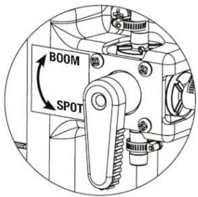
SWITCH FROM BOOM SPRAY TO SPOT SPRAY
Turn switch to the desired spray option.
text_image
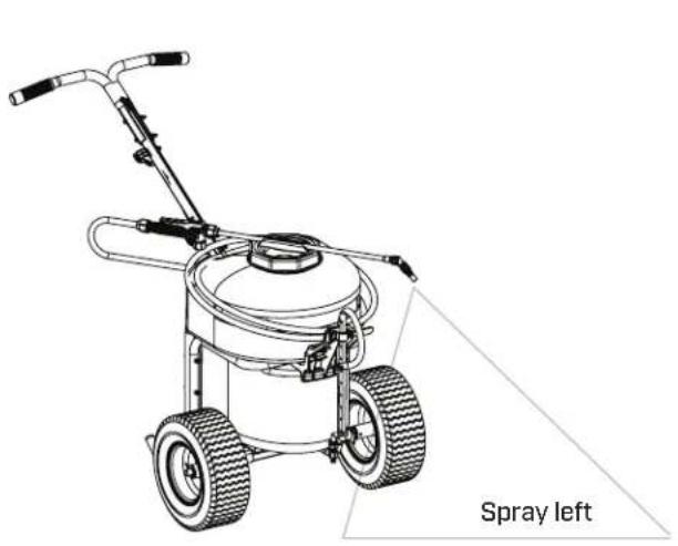
BOOM SPOTSPRAY PATTERN ADJUSTMENT FOR PUSH SPRAYING
Easily spray to left or right with positionable wand holder built right into the cap.
text_image
Spray left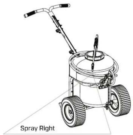
natural_image
Line drawing of a spray sprayer machine with labeled 'Spray Right' (no other text or symbols)Loosen the cam lock handle to adjust the height of the nozzle bar.
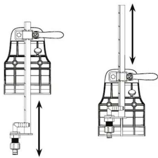
natural_image
Technical line drawings of two mechanical valve assemblies with directional arrows indicating movement (no text or symbols)Failure to do so may result in damage to property and/or person.

natural_image
Line drawing of a two-wheeled lawn mower with visible blades and handle (no text or symbols)
natural_image
Hand inserting a 24V battery into a black housing (no visible text or symbols)Figure A
natural_image
Technical line drawing of a mechanical device with internal components and no visible text or symbols
natural_image
Close-up of a hand pressing down on a car's seat, with a downward arrow indicating the pressure point (no text or symbols visible)Figure B
text_image
C-8 H-12 H-1 H-1 H-1 H-1 C-9 H-1 H-1 H-1 H-1 H-1 H-1 C-4 H-1 H-12
text_image
H-1 H-1 C-5 C-4 H-1 H-12.1
text_image
e la varilla [H-9] H-1 H-9 H-1 C-5 H-1 H-9 H-1 C-43
text_image
H-11 C-10 H-1 H-1 H-10 C-11 H-1 H-1 H-11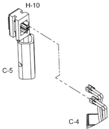
text_image
H-10 C-5 C-45
text_image
H-7 H-3 Bendtext_image
C-6 C-7 H-4 H-2 Assembled7
FIJE EL SOPORTE DE LA BOQUILLA Y LA BOQUILLA AJUSTABLE AL TANQUE
text_image
H-5 H-2 H-6 H-6 Assembled8
ENSAMBLE LA DESCARGA A LA VÁLVULA DERIVADORA
text_image
BOOM SPOTnatural_image
Line drawing of a spray sprayer machine with labeled 'Spray Right' (no other text or symbols)AJUSTE LA ALTURA DE LA BOQUILLA
natural_image
Technical line drawings of two mechanical valve assemblies with directional arrows indicating movement (no text or symbols)Failure to do so may result in damage to property and/or person.
natural_image
Line drawing of a manual lawn mower with two wheels and handlebars (no text or symbols)
RECOMMANDATIONS D'ENTREPOSAGE
natural_image
Hand inserting a 24V battery into a black case (no text or symbols visible)Figure A
natural_image
Close-up of a mechanical component with internal features and mounting holes (no visible text or symbols)natural_image
Technical line drawing of a mechanical device with internal components and an arrow indicating direction (no text or symbols)
natural_image
Close-up of a hand pressing down on a mechanical component, labeled 'APIN 24v' with a downward arrow (no readable text beyond label)Figure B
text_image
C-8 H-12 H-1 H-1 H-1 H-1 C-9 H-1 H-1 H-1 H-1 H-1 H-1 C-4 H-1 H-12
INSTALLATION DU GUIDON
text_image
H-1 H-1 C-5 C-4 H-1 H-12.1
text_image
es de tube [H-9] H-1 H-9 H-1 C-5 H-1 H-9 H-1 C-43
ASSEMBLER L'ÉLÉMENT FILTRANT ET LE COUVERCLE
text_image
H-11 C-10 H-1 H-1 H-10 C-11 H-11 H-1 H-1 H-10 C-5 C-45
INSTALLATION DE L'AXE ET DE LA ROUE
text_image
C-6 C-7 H-4 H-2 Assembled7
ATTACHEZ LE SUPPORT DE BUSE ET LA BUSE RÉGLABLE AU RÉSERVOIR
text_image
H-5 H-2 H-6 H-6 Assembled8
ASSEMBLER LA DÉCHARGE À LA VANNE DE RÉPARTITION
natural_image
Technical line drawing of a mechanical assembly (no text or symbols)Figure C
9
ASSEMBLER LA LANCE DE RALLONGE POUR ARRÊT
text_image
BOOM SPOTRÉGLAGE DU SCHÉMA DE PULVÉRISATION POUR LA PULVÉRISATION POUSSÉE
text_image
Spray RightAJUSTEZ LA HAUTEUR DE LA BUSE
natural_image
Technical line drawings of two mechanical valve assemblies with directional arrows indicating movement (no text or symbols)REPLACEMENT PARTS PARTES DE REPUESTO PIÈCES DE RECHANGE
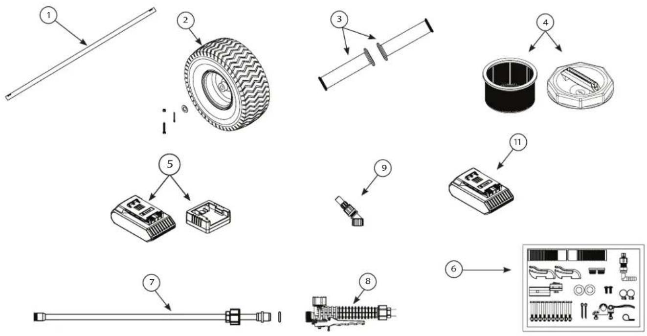
text_image
Exploded view diagram of automotive tire assembly with numbered parts and component labelsREF NO. QTY PART NO. DESCRIPTION / DESCRIPCIÓN / DESCRIPTION
| 1 | 1 | 6-9134 Drive shaft, Fletcha de transmisión, Arbre de transmission |
| 2 | 1 | 6-9078 Wheel w/hardware, Ruedas C/herrajes, Roues avec matérie |
| 3 | 1 | 6-9062 Handle Grips, Cubiertas de manijas, Prises de poignées |
| 4 | 1 | 6-8146-1 Filter Basket and Cap , Tapón y canastilla del filtro, Panier du filtre et bouchon |
| 5 | 1 | 6-8238 Battery and Charger, Batería y cargador, Batterie et chargeur |
| 6 | 1 | 6-9107 Hardware Blister Kit, Kit del brazo, Trousse de rampe |
| 7 | 1 | 6-8219 Wand Assembly, Ensamlbaje de la varilla, Assemblage de tube |
| 8 | 1 | 6-8138 Shut-off Assembly, Unidad de cierre, Assemblage d'arrêt |
| 9 | 1 | 6-9075 Nozzle Kit, Kit de boquilla, Trousse de buse |
| 10 | 1 | 6-8239 24V Battery, Batería 24V, Batterie 24V |

P.O. Box 549 700 Ellicott St.
Batavia, NY 14021-0549 U.S.A.
1-800-950-4458 www.chapinmfg.com
© 2023 Chapin International, Inc.
Due to our ongoing product improvement process, product specifications may change without notice.