
Switchblade 50 Combo - Audio Amplifier HUGHES & KETTNER - Free user manual and instructions
Find the device manual for free Switchblade 50 Combo HUGHES & KETTNER in PDF.

| Product Type | Audio amplifier for electric guitar |
| Brand | Hughes & Kettner |
| Model | Switchblade 50 Combo |
| Number of channels | 4 (Clean, Crunch, Lead, Ultra) |
| Output power | 50 Watts RMS |
| Power tubes | EL34 (matched) |
| Preamp tubes | 12AX7 (selected) |
| Built-in speaker | 1 x 12" Eminence Rockdriver 60 |
| Output impedances | 1 x 4 Ω, 1 x 8 Ω / 2 x 16 Ω, 1 x 16 Ω |
| Digital effects | Reverb, Delay, Modulation (Chorus/Flanger/Tremolo) |
| MIDI | Input and Thru (5-pin, phantom power 7-pin) |
| Effects loop | SmartLoop™ switchable Series/Parallel with adjustable level |
| Presets | 128 (32 banks of 4) |
| Included footswitch | FSM 432 (MIDI controller) |
| Dimensions (W x H x D) | 600 x 500 x 285 mm |
| Weight | 22.8 kg |
| Mains power | 100-120 V or 220-240 V (selectable), 50-60 Hz |
| Max consumption | 290 Watts |
| Instrument input | 6.35 mm unbalanced jack, impedance 1 MΩ |
| Maintenance | Dust regularly, replace tubes by a technician, use the Standby switch for breaks |
| Safety | Do not use without speaker, respect impedances, disconnect from mains before maintenance |
| Serviceability | Replacement of tubes and fuses by a professional; parts available from the manufacturer |
Frequently Asked Questions - Switchblade 50 Combo HUGHES & KETTNER
User questions about Switchblade 50 Combo HUGHES & KETTNER
0 question about this device. Answer the ones you know or ask your own.
Ask a new question about this device
Download the instructions for your Audio Amplifier in PDF format for free! Find your manual Switchblade 50 Combo - HUGHES & KETTNER and take your electronic device back in hand. On this page are published all the documents necessary for the use of your device. Switchblade 50 Combo by HUGHES & KETTNER.
USER MANUAL Switchblade 50 Combo HUGHES & KETTNER
Head und Combo
5.2 Channel Select
$$ R = (R 1 \times R 2) / (R 1 + R 2) $$
$$ R = (8 \times 1 6) / (8 + 1 6) $$
$$ R = 1 2 8 / 2 4 $$
$$ R = 5, 3 3 $$
HEAD / COMBO 100

COMBO 50

For another first in guitar amp history, Hughes & Kettner ^2 has packed all the features guitarists have long been dreaming of into one amp – a bona fide all-tube design and the boundless versatility of amp modeling.
For more than 20 years, Hughes & Kettner ^® has engineered trailblazing amp designs that explore new frontiers in the powers and possibilities of musical expression. Milestones such as the AS 64 (the world's first fully-programmable amp), the Access (the first programmable tube preamp), the TriAmp (the first six-Channel tube amp) and zenTera (today the undisputed boss among digital amps) raised the bar for technical and tonal excellence. Each of these amp's DNA is in SWITCHBLADE's genes. And it's this unique combination of inheritance and innovation that made this groundbreaking concept possible in the first place.
Best wishes from the Hughes & Kettner ^® team. We hope you enjoy playing your SWITCHBLADE as much as we enjoyed designing and refining it!
Things to Do Before Operating the Amp
Please read the safety instruction on page 64!
A word of warning before you fire up your SWITCHBLADE: It's loud! High volume levels can cause hearing damage.
Ensure plenty of air can circulate around your amp's ventilation surfaces. Place the amp on a sturdy, secure base and avoid exposing it to mechanical shocks and extreme temperatures that could endanger the device or your and others' safety.
The manufacturer disclaims any liability or responsibility whatsoever for any damage or defect to this and other devices resulting from misuse.
Powering Up
Ensure SWITCHBLADE's MAINS and STANDBY switches are off (with the toggle switch pointing down) and that the voltage rating indicated next to the MAINS INPUT (alongside the Voltage Setting arrow as depicted the illustration) matches your local Mains current before you plug the amp in.
The illustration shows the 100/120 volt version as an example. The voltage rating 100V is indicated next to the arrow, meaning that the amp may be powered with 100V Mains voltage only. If the rating indicated next to the arrow does not match the local Mains voltage, do not plug your Switchblade's Mains cord into an outlet! More on this in chapter 8.1.
Head Only
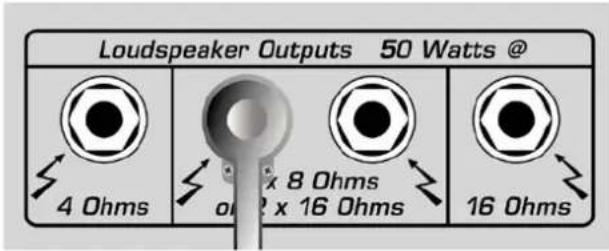
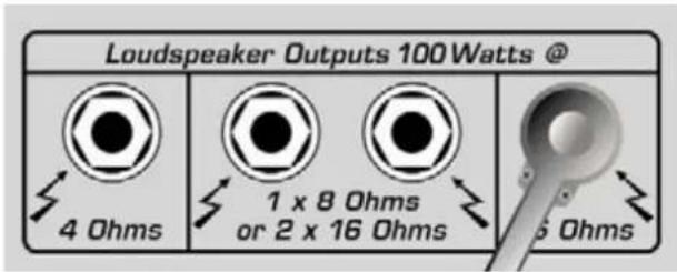
First plug the speaker cord into the appropriate output on the Head. Do not use more than one of these outputs simultaneously! That is, use either 1x4 ohms, 2x16 ohms, 1x8 ohms, or 1x16 ohms. Don't mix and match cabinets either, say by plugging a 4-ohm cabinet into the 4-ohm output and a 16-ohm cabinet into the 16-ohm output. For more on this, see chapter 5.5.
Plug the other end of the cord into the speaker cabinet's Input. This is vital to every all-tube amp's life! Power amps may be damaged when tube amps are operated without a connected speaker load or at an insufficient impedance level!
Combo Only
Check to ensure the wire to the internal speaker is connected properly to the power amp (see figure). Note that on the 50W Combo, the internal speaker is connected to the 8-ohm output. On the 100W Combo, it is connected to the 16-ohm output.
Head and Combo
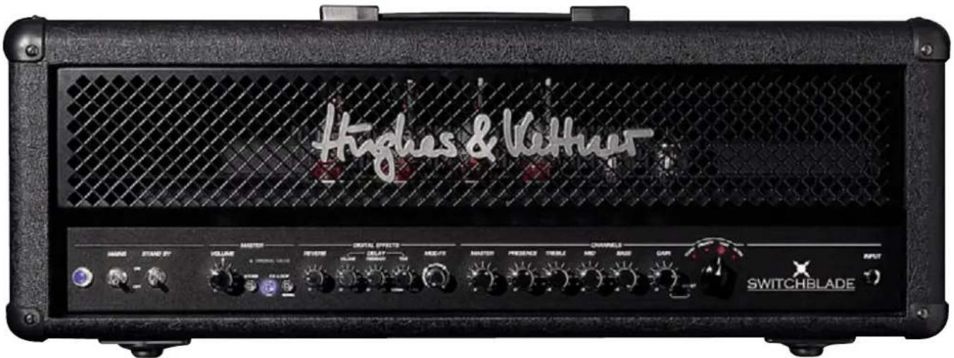
To avoid very unpleasant surprises, make a habit of always twisting the MASTER VOLUME knob to the far left-hand position before turning on the amp.
Input
Connect your guitar to this Input. Please use suitable shielded cords only – no speaker cords allowed.
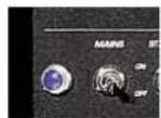
Mains
This switch opens the flow of main current supply, and the blue PILOT LAMP lights up. Ensure the STANDBY switch is set to OFF and allow the tubes plenty of time to warm up. They'll thank you for your patience with a longer service life.
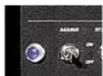
Standby
The STANDBY switch breathes life into those glowing tubes. It controls the anode voltage, not the heating. When taking a short break from playing, please use STANDBY rather ON/OFF so the tubes remain at operating temperature.
If you can't wait to get to it, go ahead and play your SWITCHBLADE now. The patient reader is well advised to continue reading before letting it rip. Particularly chapters 1 (Handling) and 6 (Programming) are mandatory, even for seasoned players.
Standard Setup and Cable Connections
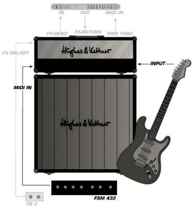
Table of Contents
1 The Fundamentals of Handling SWITCHBLADE
2 The SWITCHBLADE's Channels
2.1 CLEAN Channel
2.2 CRUNCH Channel
2.3 LEAD Channel
2.4 ULTRA Channel
2.5 GAIN
2.6 BASS, MID, TREBLE
2.7 PRESENCE
2.8 MASTER
3 Digital Effects
3.1 REVERB
3.2 DELAY
3.3 MOD FX
4 Master
4.1 VOLUME
4.2 STORE
4.3 ORIGINAL VALUE
4.4 FX LOOP
5 Rear Panel Connections and Control Features
5.1 EFFECTS ON/OFF
5.2 CHANNEL SELECT
5.3 FX LOOP
5.4 MIDI
5.5 SPEAKERS
6 MIDI Control and Programming
6.1 FSM 432
6.2 Setting SWITCHBLADE's MIDI Channel and Switching OMNI ON/OFF
6.3 Factory Settings and How to ReStore Them
6.4 Storing Settings/Programming
7 Replacing Tubes, Service and Preventive Maintenance
8 Troubleshooting
9 Technical Specifications
1 The Fundamentals of Handling
SWITCHBLADE is a tube amp and, as such, works like as a tube amp. Nevertheless, the handling concept is rather advanced, so time spent familiarizing yourself with it is time well spent.
At first glance, the knobs look and feel like standard-issue gear: Control range 300 degrees; 0-10 clockwise; left and right stops.
At second glance, though, you'll discover that there is just a single set of knobs to serve all four Channels. One GAIN, one Channel MASTER, one three-band EQ – that's it. The selected Channel determines if the GAIN knob addresses the CLEAN, CRUNCH or LEAD Channel.
The great advantage of this concept is that Channels are independent and do not share the Gain, Master or voicing knobs; even Presence is separately adjustable for every Channel and every setting can be programmed individually to each of the 128 Presets!
Apart from the VOLUME MASTER knob (and of course MAINS and STANDBY), this applies to all of SWITCHBLADE's control features, that is:
- the Channels: CLEAN, CRUNCH, LEAD, ULTRA
- the Channel settings: GAIN+BOOST, BASS, MID, TREBLE, PRESENCE, MASTER
- the effect parameters: MOD FX, TIME, FEEDBACK, VOLUME, REVERB
- the effect routing options for external devices: FX ON/OFF, SERIAL/PARALLEL

You won't find any control features for managing the 128 Presets on Switchblade. The included FSM 432 MIDI board or another MIDI-enabled controller serves to select Presets and assign memory slots. More on this in chapter 6.
Note: A knob setting programmed in a Preset and the knob's actual setting are not necessarily the same. They are independent: When you switch from one Preset to another, the knob's actual position may not
reflect the setting programmed in the Preset. This means you may well hear something other than what you're seeing would suggest. As soon as you touch the knob, it will respond like any other conventional knob. The ORIGINAL VALUE LED in the MASTER section tells you the Preset setting. It lights up as soon as the position of the knob corresponds to the Preset setting. More on this in chapter 4.3.
Note: You may hear a soft background sound when you twist the knobs. This is a switching noise made the programmable resistor matrix located behind each knob.
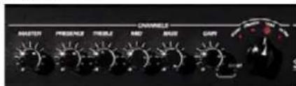
2 The SWITCHBLADE's Channels
SWITCHBLADE offers four Channels with markedly different sonic characters. Courtesy of SWITCHBLADE's programmability, you enjoy more and more powerful sound-shaping options: The knobs are not hardwired to the internal circuits, so we were able to tweak their control ranges and performance to make the most of each Channel's characteristic sound.
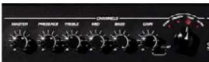
A chickenhead knob is sited at the far right of the CHANNEL section—that's the Channel Selector. Use it to switch among the four Channels along with their GAIN, BASS, MID, TREBLE, PRESENCE and MASTER settings.
Note: When you first power up your amp and change Channels, you will dial up factory settings (see chapter 6.3.2 to learn more). As soon as you begin dialing in sounds to your taste, it will adopt your Channels settings. And it recalls your most recently configured sound for each Channel. You'll find this to be a tremendous help when programming. More on this in chapter 6.
2.1 Clean Channel
Tuned to rival classic Californian tone, Switchblade's Clean Channel delivers a spectrum of sweet sounds ranging from crystal-clear to remarkably responsive Crunch tones. The programmable Presence control adds silken warmth as well as sparkling shimmer to the sonic equation.
2.2 CRUNCH Channel
Classic British overdrive à la carte! The CRUNCH Channel covers the diverse tonal spectrum from Clean to mean, and all points in between. The Gain control's integrated Boost function transforms tight rhythm tone into a throaty growl perfect for rockin' riffs.
2.3 LEAD Channel
The LEAD sound is the first choice for hard-rockin', classic British high-GAIN tone to fuel Leads, power chords and riffs. Courtesy of its fine-tuned compression, this Channel delivers the lubricant that makes those slick riffs and licks fly off your fingertips.
2.4 ULTRA Channel
American high-Gain sound with sumo-sized low end and snarling top end. The ULTRA Channel delivers the kind of merciless performance that is sure to delight nu metal meisters and dropped tuning aficionados. Ultra is also an alluring alternative for guitarists seeking to super-size their sound with a high-calorie topping of rich tone.
2.5 GAIN
The GAIN knob determines Input sensitivity and thus the Level of saturation and distortion. SWITCHBLADE's GAIN offers a special feature: Just before the knob arrives at the far right position, a BOOST stage kicks in (and the red LED lights up). Now, when you see Boost on other amps, this usually means all frequencies are boosted. But Switchblade's Boost amplifies selected frequency ranges for each Channel to attain creamier tone.
2.6 BASS, MID, TREBLE
The voicing section is tweaked to accomplish the best, most efficient sound-shaping for each Channel. Getting right to the heart of the sonic matter, every knob addresses each Channel's characteristic frequency ranges. Like on every tube amp, the knobs of a Channel influence each other. That is, if you boost the Treble, the midrange is cut and vice versa. This puts a much greater range of subtle tonal variations at your fingertips.
2.7 PRESENCE
This knob determines the overtone content. Unlike a TREBLE knob, which boosts whatever high frequencies are available, PRESENCE actually determines the amount of harmonic overtones generated by the amp. Usually a PRESENCE knob controls the overtone content of the overall amp rather than of individual Channels. Courtesy of SWITCHBLADE's programmability, you can define PRESENCE settings not only for each Channel, but also for each Preset.
2.8 MASTER
Use the Channel MASTER knob to adjust the given Channel's Volume and balance it out with the other Channels' Levels. On Switchblade this knob serves another vital purpose: It lets you store the same sound at different Volumes to any of the 128 Presets, for example, a softer version for rhythm and a louder setting for Leads.
Note: The Channel MASTER is a different breed of knob. It adjusts the Channels' relative levels, and is tweaked to help you quickly dial in the best balance. Unlike a conventional Master knob, it can't be turned
all they way Down; it merely boosts or cuts the given Level. This design makes musical and practical sense: The Clean Channel normally requires a much higher Master Level than a distorted Channel, which is why it is about as loud as the other Channels when the knob is set to the center position. That's why the 12 o'clock position is always the best starting point for adjusting Volume.
3 Digital Effects
SWITCHBLADE offers three independent digital effect sections that can be used simultaneously. Like Channel settings, all effect settings are programmable.
Note: The internal effects are added to the signal via an intelligent analog circuit. Effect routings in no way comprise the integrity of SWITCHBLADE's tube tone, which remains intact in all its quality.
3.1 REVERB
SWITCHBLADE's Reverb is modeled to match the warmth and musicality of classic spring Reverbs. A genuine improvement over its analog forebears, it automatically adjusts the Reverb tail to suit the setting: The more REVERB you add to the signal, the longer the REVERB time.
3.2 DELAY
The Delay section's VOLUME, TIME and FEEDBACK knobs afford you total control over all parameters. This lets you dial in everything from rockabilly style slap-back echo to U2-inspired Delay extravaganzas and Queen-like bombast.
3.2.1 VOLUME
Adjusts the Volume of the repetitions, sweeping from all the way off to just as loud as the original signal.
3.2.2 FEEDBACK
Adjusts the number of repetitions from one to infinite.
3.2.3 TIME
Adjusts the Time to the next repetition from 80 ms to 1.4 s.
TIP: TIME can be remote-controlled via the included FSM 432 using the TAP function. This lets you respond quickly and conveniently to timing changes. You'll find TAP to be a very helpful feature, particularly on stage! More on this in chapter 6.1.3
3.3 MOD FX
The three most important modulation effects are CHORUS, FLANGER and TREMOLO, and they're all on board, readily activated via a single knob. CHORUS is active in the first third, FLANGER in the second third, and TREMOLO in the final third of the control range. You can shape the effect within its assigned third of the control range using this knob. The parameters were tweaked to make musical sense: A twist of the knob is all it takes to get the desired effect. Twisting clockwise adjusts the rate of the modulation effects. Modulation depth is adjusted
automatically according to the rate so that every knob position gives you the best effect sound. To switch modulation effects off, simply twist the knob to the far left-hand position.
3.3.1 CHORUS
At slow settings, the CHORUS sounds thick and lush, providing a great sound for buoyant ballads. And because effect depth is adjusted automatically, fast CHORUS settings don't evoke that dreaded seasick tone.
3.3.2 FLANGER
Slow FLANGER settings yield a stately sweeping whoosh effect, while faster settings give you swirly effects often heard in contemporary rock and pop tunes.
3.3.3 TREMOLO
The classic TREMOLO effect is great for dialing in typical sounds of the '60s as well as contemporary effect sounds.
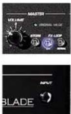
4 Master
The Master section lets you adjust the amp's overall Volume, route external effects, and store Presets.
4.1 VOLUME
As the name would indicate, this knob puts the power amp at your thumb and forefinger's command. Exercise restraint when handling this knob to make music a pleasant rather than a painful experience.
Handling: Unlike the Channel and effect knobs, the MASTER VOLUME knob is not programmable! It works like any standard knob, and the position of the knob indicates the actual setting.
Caution: High volume levels can cause hearing damage. Spare yourself a nasty surprise and twist the MASTER VOLUME knob to the far left-hand position before powering the amp up.
4.2 STORE
Use the STORE button to save your Presets. See chapter 6.4 for more info.
4.3 ORIGINAL VALUE
This LED tells you which knob setting is stored in the given Preset. To this end, select a Preset, grab the knob and twist it to the left or right until this LED lights up. The setting at which the LED lights up corresponds to the setting stored in the Preset.
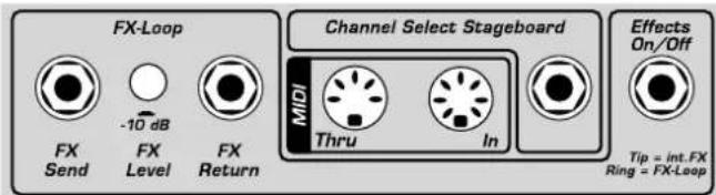
4.4 FX LOOP
SmartLoop™ is a special effects routing circuit offering a switchable Parallel/Serial effects loop for patching in external effect devices. Its status is stored in each Preset, that is, whether it is on or off and configured in a parallel or serial circuit.
4.4.1 SERIAL
Switches the effects loop from Parallel (LED does not light up) to Serial (LED lights up).
4.4.2 FX ON
Switches the effects loop on (LED lights up) and off (LED does not light up).
Tip: If you have not inserted an effect device into the FX Loop, you can use this circuit for other purposes and store the configurations individually in each preset:
- In parallel mode, you can use the RETURN jack to connect a second instrument or any other audio source. You can also route the amp's signal to a second power amp.
- In serial mode, the effects loop lets you control the amp's volume remotely by simply connecting an analog Volume pedal to SEND/RETURN.
Caution: The signal chain is severed if the effects loop is configured serially and no effect device is connected. Send is not the best to-mixer routing option because it accesses the preamp signal only. Patch the power amp signal to a mixing console via the Hughes & Kettner Red Box® and the speaker outputs.
5 Rear Panel Connections and Control Features
5.1 EFFECTS ON/OFF
This port accepts the two-way Hughes & Kettner ^® FS-2 footswitch. Button 1 switches internal effects; button 2 the external effects loop. The FS-2's LED lights up to indicate effects are active and the FX ON button is engaged. It does not light up if the internal effects are bypassed or the FX ON button is switched off.
Note: The footswitch deactivates the FX ON button on the front panel! When a footswitch is connected, it always has priority. The current status of the footswitch is valid when switching Channels, irrespective of the switching status stored in the preset! The front panel FX ON button now serves as an LED display indicating the status of the footswitch.
5.2 CHANNEL SELECT
If you ever leave your MIDI board behind, this flexible fall-back connector for footswitches will help get you through the gig. It lets you switch remotely between two Channels, say CLEAN and ULTRA, using standard one-way footswitches such as the Hughes & Kettner ^® FS-1. A two-way footswitch such as the Hughes & Kettner ^® FS-2 may also be connected. In this case, button 1 is responsible for the Channels, and button 2 is disabled. SWITCHBLADE even accepts the four-way Hughes & Kettner ^® FS-4 footswitch that ships with Hughes & Kettner ^® Trilogy and Matrix amp. It lets you switch all four Channels.
Note: The footswitch changes the Channels only, and not presets. That is, it activates the most recent Channel settings and it does not switch effects.
5.3 FX LOOP
If you wish to use an external effect device, you can insert it into the FX LOOP.
5.3.1 FX SEND
Connect this jack to your effects processor's input jack.
5.3.2 FX LEVEL
This button cuts the FX SEND's output level by 10 dB and boosts the FX RETURN's input sensitivity by 10 dB to match the FX Loop to the effect device's input level. Press this button when using processors designed to handle instrument levels.
5.3.3 FX RETURN
Connect this jack to your effects processor's output.
5.4 MIDI
SWITCHBLADE is MIDI-enabled, meaning that it communicates with other MIDI devices.
5.4.1 MIDI IN
Connect the included Hughes & Kettner® FSM 432 or any other MIDI sender to this port so that you can select and switch Presets remotely. Though this is a seven-pin port, you can connect a standard five-pin MIDI cable. The two additional terminals serve to supply phantom power to the FSM 432.
5.4.2 MIDI THRU
This port forwards signals patched into the MIDI IN port to other devices. You can connect any external MIDI-enabled signal processor or any MIDI receiver that you wish to switch synchronously with SWITCHBLADE.
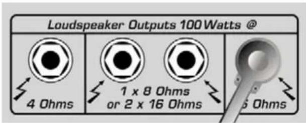
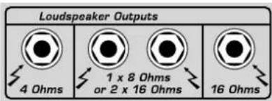
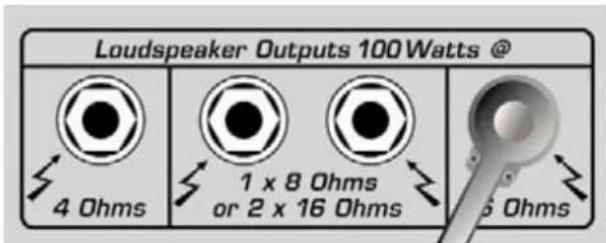
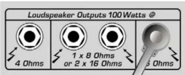
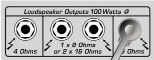
5.5 SPEAKERS
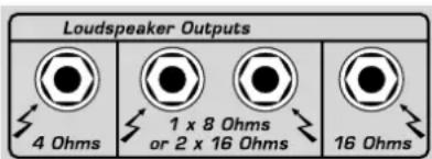
SWITCHBLADE offers separate outputs for all standard impedances: You have 1 x 4-ohm, 1 x 8/2 x 16-ohm, and 1 x 16-ohm outputs at your disposal. Always ensure the impedance (that is, the ohm value) is correct. Mismatches can corrupt the sound (high-impedance speaker connected to a low-impedance output) and harm the amp (low-impedance speaker connected to a high-impedance output).
Note: You may of course connect several cabinets to one port, even if they have different impedances. Usually speaker cabinets are connected in Parallel. Two cabinets of the same impedance connected in Parallel have half the impedance of a single cabinet. For example, if you have two 8-ohm cabinets, you must connect these to the 4-ohm output. If you connect two cabinets with different impedances (R1, R2)
in parallel, the resulting resistance R is calculated by multiplying the two individual resistances and dividing their product by the sum of the individual resistances. Use the following formula to do this:
$$ R = \left{R 1 \times R 2 \right} / \left{R 1 + R 2 \right} $$
Take as an example a one 8-ohm and one 16-ohm cabinet:
$$ R = (8 \times 1 6) / (8 + 1 6) $$
$$ R = 1 2 8 / 2 4 $$
$$ R = 5. 3 3 $$
The cabinets' impedance may never be lower than the amp's output impedance, so this combination must be connected to the 4-ohm output. However, we strongly advised against configuring setups with mismatched cabinets, and highly recommend using combinations of cabinets with the same impedance!
6 MIDI Control and Programming
6.1 FSM 432
The included Hughes & Kettner ^® FSM 432 MIDI board is a remote control serving to select the 128 memory slots conveniently arranged in 32 Banks of four presets each. You can easily configure setups any way you wish, say by assigning the four presets of a bank to a song.
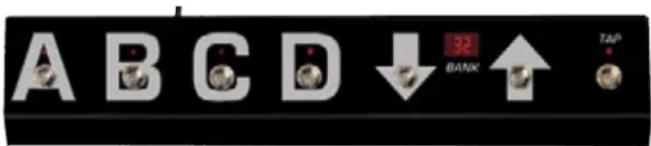
6.1.1 PRESET A B C D
Presets within a bank can be activated directly, that is, switching from A to B within the same bank occurs immediately. The LED above the A,B,C,D buttons indicates the preset.
6.1.2 BANK UP/DOWN
If you want to call up a preset in another bank, you can select the bank via UP and DOWN while continuing to play using the current preset. The number of the bank is indicated in the display, and it flashes until you select a preset via A,B,C,D. Not until then will SWITCHBLADE load the new preset.
DIRECT MODE is available if you wish to trigger a direct program change via bank Up/Down. In this mode, the FSM 432 will not wait for your input, instead switching immediately, for example, from preset B in bank 16 to preset B in bank 17 (UP) bank or 15 (DOWN). Direct Mode is activated as follows:
- Press and hold TAP, and then press PRESET A.
- First release PRESET A, and then TAP: The decimal point in the display lights up.
Follow the same sequence to deactivate DIRECT MODE. Volatile rather than permanent, DIRECT MODE is automatically deactivated when you power SWITCHBLADE down!
6.1.3 TAP
The TAP function gives you a very fast and convenient option for changing the Delay's TIME parameter. TAP comes in particularly handy on stage: Simply tap your foot on the TAP button in Time with the groove to match delay Time to the tempo. The effect adopts the new time after the second tap. The TAP LED flashes for about five seconds in time with the beat to give you a visual indication of the delay time.
Note: The TAP function works only when the DELAY is active. If the DELAY is off, the effect will not adopt your TAP tempo.
6.1.4 Switching External Devices via the FSM 432, Setting the MIDI Send Channel
If you wish to switch devices connected to SWITCHBLADE MIDI THRU – say, a MIDI effect device – using the FSM 432, ensure the effect device is set to the FSM 432's MIDI Channel or to OMNI. Consult the device's manual for more info.
To set the FSM 432's MIDI Send Channel, proceed as follows:
- Turn SWITCHBLADE on while pressing the FSM 432's PRESET A button. The display flashes.
- Release button A. Use UP/DOWN to view and set the MIDI Channel to a number between 1 and 16.
- Quit and store by pressing the PRESET A button.
Caution: If SWITCHBLADE and FSM 432 are not set to the same MIDI channel, the amp will not respond to program changes! Activating OMNI solves the problem in the event of an "emergency." See chapter 6.2 to learn more.
Note: If an external effect device is connected to MIDI THRU and you want to switch Switchblade and the effect device simultaneously with the same program change command, you must configure Switchblade's Store function and program this device accordingly.
Note: The table above should be big help if you wish to switch the Presets of a device connected to the MIDI THRU directly via the FSM 432. It shows the program changes sent by the bank/preset combination. Please bear in mind that some MIDI devices switch program 1 via program change command 0. If this is the case with your outboard gear, simply add a 1 to each value indicated in this table to activate the desired program.
| Bank | Preset | Programchange Number | Bank | Preset | Programchange Number | Bank | Preset | Programchange Number | Bank | Preset | Programchange Number |
| 1 A | 0 9 A | 32 17 | A 64 | 25 A | 96 | ||||||
| 1 B | 1 9 B | 33 17 | B 65 | 25 B | 97 | ||||||
| 1 C | 2 9 C | 34 17 | C 66 | 25 C | 98 | ||||||
| 1 D | 3 9 D | 35 17 | D 67 | 25 D | 99 | ||||||
| 2 A | 4 10 | A 36 | 18 A | 68 26 | A 100 | ||||||
| 2 B | 5 10 | B 37 | 18 B | 69 26 | B 101 | ||||||
| 2 C | 6 10 | C 38 | 18 C | 70 26 | C 102 | ||||||
| 2 D | 7 10 | D 39 | 18 D | 71 26 | D 103 | ||||||
| 3 A | 8 11 | A 40 | 19 A | 72 27 | A 104 | ||||||
| 3 B | 9 11 | B 41 | 19 B | 73 27 | B 105 | ||||||
| 3 C | 10 11 | C 42 | 19 C | 74 27 | C 106 | ||||||
| 3 D | 11 11 | D 43 | 19 D | 75 27 | D 107 | ||||||
| 4 A | 12 12 | A 44 | 20 A | 76 28 | A 108 | ||||||
| 4 B | 13 12 | B 45 | 20 B | 77 28 | B 109 | ||||||
| 4 C | 14 12 | C 46 | 20 C | 78 28 | C 110 | ||||||
| 4 D | 15 12 | D 47 | 20 D | 79 28 | D 111 | ||||||
| 5 A | 16 13 | A 48 | 21 A | 80 29 | A 112 | ||||||
| 5 B | 17 13 | B 49 | 21 B | 81 29 | B 113 | ||||||
| 5 C | 18 13 | C 50 | 21 C | 82 29 | C 114 | ||||||
| 5 D | 19 13 | D 51 | 21 D | 83 29 | D 115 | ||||||
| 6 A | 20 14 | A 52 | 22 A | 84 30 | A 116 | ||||||
| 6 B | 21 14 | B 53 | 22 B | 85 30 | B 117 | ||||||
| 6 C | 22 14 | C 54 | 22 C | 86 30 | C 118 | ||||||
| 6 D | 23 14 | D 55 | 22 D | 87 30 | D 119 | ||||||
| 7 A | 24 15 | A 56 | 23 A | 88 31 | A 120 | ||||||
| 7 B | 25 15 | B 57 | 23 B | 89 31 | B 121 | ||||||
| 7 C | 26 15 | C 58 | 23 C | 90 31 | C 122 | ||||||
| 7 D | 27 15 | D 59 | 23 D | 91 31 | D 123 | ||||||
| 8 A | 28 16 | A 60 | 24 A | 92 32 | A 124 | ||||||
| 8 B | 29 16 | B 61 | 24 B | 93 32 | B 125 | ||||||
| 8 C | 30 16 | C 62 | 24 C | 94 32 | C 126 | ||||||
| 8 D | 31 16 | D 63 | 24 D | 95 32 | D 127 |
6.2 Setting Switchblade's MIDI
Channel and Switching OMNI ON/OFF
Press the SERIAL button longer than two seconds when SWITCHBLADE is in normal operating mode, and the ORIGINAL VALUE LED will start flashing. This assigns special programming functions to the amp's LEDs and buttons:
FX ON
Now serves as a +1/UP button for setting the MIDI Channel.
Serial
Now serves as a -1/DOWN button for setting the MIDI Channel.
Store
OMNI ON/OFF switches. If the STORE button (OMNI On) lights up, SWITCHBLADE responds to all incoming program changes, irrespective of the MIDI Channel over which they are sent. If the light on the button is extinguished (OMNI OFF), it responds only to messages sent via the defined MIDI Channel.
FACTORY SETTING: MIDI CHANNEL = 1, OMNI = ON
Note: OMNI ON is helpful if you are unsure via which channel a connected MIDI device sends its messages.
During the MIDI setup routine, the LEDs that normally indicate the preamp Channel indicate the MIDI Channel. The following table MIDI Channel lists the MIDI Channel settings in what is called binary code:
| MIDI-Kanal | Boost | Clean | Lead | Ultra | ||
| 1 | ||||||
| 2 | ||||||
| 3 | ||||||
| 4 | ||||||
| 5 | ||||||
| 6 | ||||||
| 7 | ||||||
| 8 | ||||||
| 9 | ||||||
| 10 | ||||||
| 11 | ||||||
| 12 | ||||||
| 13 | ||||||
| 14 | ||||||
| 15 | ||||||
| 16 |
Press and hold SERIAL for a few moments to quit the MIDI setup routine and store the settings. The amp returns to its most recent operating status (normal mode).
6.3 Factory Settings and Factory Reset
A factory reset is a seldom needed feature. Nevertheless, be sure to read the explanation carefully to ensure you don't accidentally delete your presets.
6.3.1 Triggering a Factory Reset
If you press STORE and FX SERIAL simultaneously while powering the amp, all settings are reset, including the 128 MIDI-switchable presets and the basic MIDI configuration.
6.3.2 Factory Presets and Basic MIDI Configuration
The Switchblade is delivered ex-factory with 64 different presets (memory slots 1-64). In the memory slots 65-125 you will find copies of the first 64 presets. You may find a list of all the presets on the accompanying sheet.
The basic MIDI configuration is:
• OMNI ON
- MIDI Channel: 1
- FX ON is switched off.
- SERIAL is deactivated.
Caution: This procedure is a last-resort option! It irrevocably wipes out all stored settings.
6.4 Storing Settings/Programming
You have two options for storing a preset to one of the 128 memory slots: Select a new memory slot via MIDI (6.4.1) or overwrite the preset directly at the device (6.4.2).
6.4.1 Selecting a New Memory Slot via MIDI Learn
- Press the STORE button briefly; it lights up to signify that it is armed (MIDI Learn).
- Select a MIDI bank from 1 to 32 on the FSM 432; it flashes to signify that the FSM 432 is waiting for input via one of the four preset buttons A to D.
- Engage preset button A,B,C or D; the board stops flashing, the light on the STORE button extinguishes, and the preset is stored.
Caution: When the FSM 432 is in DIRECT MODE (see chapter 6.1.2), a BANK UP/DOWN command also triggers the storage process! We recommend deactivating Direct Mode when programming to prevent inadvertent overwriting of presets.
Note: Here's how to proceed for other manufacturers' MIDI boards and MIDI-enables devices: Arm SWITCHBLADE by engaging the STORE button and selecting the desired memory slot. As soon as SWITCHBLADE receives a valid program change command, the STORE button extinguishes and the preset is stored.
If an error occurs (the amp remains armed), you can cancel the storage process by pressing STORE again.
6.4.2 Overwriting Presets Directly at the Device
There is an easier way to overwrite the most recently selected preset than going from the amp to the MIDI board and back after every edit: Press and hold the STORE button until its light extinguishes (after about two seconds). The ORIGINAL VALUE and the Channel LEDs also flash to confirm. Then you can release the STORE button and your settings are stored.
7 Replacing Tubes, Service and Preventive Maintenance
SWITCHBLADE is factory-loaded with EL34 and 12AX7 tubes. Once they've been burned in – that is, operated continuously under a load –they are subjected to a rigorous selection process. Their electrical specs and mechanical status (microphonics) are checked, and then they are installed in an amp and their sonic performance is auditioned. One of the most important steps in this process is tube matching, whereby tubes with the same characteristics are teamed up in matched sets of power tubes.
When to Replace Tubes
The tubes in SWITCHBLADE are exemplary in terms of quality, workman-ship and long service life. Nonetheless, tubes show definite signs of wear when their service life is nearing its end. Telltale signs are increased microphonics, noise and hiss, muddler tone through loss of high-end frequencies, degraded performance, etc. Take these indications seriously and replace old tubes. Not only do these side effects take their toll on sound quality, they also indicate the aging tube will soon fail!
Note: Replacing tubes for experimentation purposes is not recommended. Installing the wrong tubes will damage the amp and cost you a lot more than you bargained for in repair costs.
Before you start swapping tubes, ask yourself these questions:
- Was the fault or failure of the tube caused by the tube itself or by a flawed peripheral device or component, perhaps a defective speaker cable? If you don't get to the bottom of the problem and remedy it, it may crop up again even after you replace the tubes.
- Did the Mains voltage fluctuate or spike while the amp was on? In all-tube amps, over-voltage surges in the Mains net can certainly cause drop-outs. Over-voltages are often caused by generators and faulty high-current power circuits.
- Perhaps a fuse blew even though none of the tubes is actually defective? An old fuse, tube de-ionization or Mains voltage power surges may have triggered the fuse.
Things to Bear in Mind When Replacing Tubes
Replacing tubes is a job best left to qualified professionals!
Accordingly, the following guidelines are addressed and apply to qualified service technicians only:
- Pull Switchblade's Mains plug and allow for a discharge time of at least two minutes before removing the chassis from the rear of the amp.
- Once the chassis has been removed, carefully ease the tubes out of their sockets.
- A single power tube may only be replaced if the replacement tube precisely matches the original, that is, the old and new tubes' characteristics are identical.
- When a new matched set of power tubes with characteristics identical to the old set is installed, it is not absolutely necessary to re-bias the amp.
- The amp must be biased when a replacements set's characteristics do not match the original set's. This requires experience and extensive working knowledge in measuring techniques, which is why this is a job for qualified technicians with tube amp tuning experience.
How to Prolong Tube Life
- Never operate Switchblade without connecting a load (loudspeaker)!
- Never connect speaker cabinets with an impedance that is too high or low!
- Always use high-quality, heavy-duty speaker cords that won't crimp!
• Use the STANDBY switch for short breaks! - Avoid exposing the amp to vibrations, especially when it's powered up.
- Switch the amp off well before transporting it to allow tubes to cool off completely.
- Make sure all peripheral devices and connecting cords are in a state of good repair!
- Ensure air can circulate freely around the amp's ventilation slots at all times!
- Never expose Switchblade to extreme heat or cold!
- Prevent the intrusion of dust and moisture!
- Always check peripheral gear's specs to ensure these accessories are suitable for the amp.
- Never connect devices with high output signal Levels to Switchblade's Input.
- Never operate the amp with Mains power that is too high or too
low. When in doubt ask the venue's sound technician or facility engineer.
- Refrain from DIY repairs! Also have a qualified technician replace internal fuses.
8 Troubleshooting
Mains connection: SWITCHBLADE
won't power up when you switch it on.
- It's not getting AC power. Check the Mains cord to see if it is connected and firmly seated.
- The Mains fuse is defective. Ensure it is replaced with another fuse bearing the same rating.
- The local Mains voltage does not match Switchblade's operating voltage
Available Voltages and How to Adapt Them
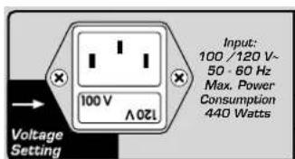
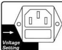
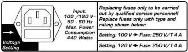
Switchblade ships in two versions rated for 110/120V and 220-240V. You will find the rating indicated on the housing above the Mains socket. Both models offer two operating voltages that are selected using the voltage selector integrated in the Mains socket. Ensure that the Mains voltage matches the voltage rating appearing in the voltage selector window. This value is legible when the amp is in the standard operating position, that is, placed right side up. The upright number indicates the currently selected voltage, and the inverted number indicates the alternative voltage. Check also the fuse ratings to ensure they match the ratings indicated on the rear panel.
Voltage selection and fuse replacement may be performed by experienced service technicians only. Accordingly, the following notes are addressed exclusively to service technicians:
- Use a small flat screwdriver to remove the voltage selector from the Mains socket.
- If the fuse is defective, replace it with a fuse bearing the specified rating.
- Turn the voltage selector and insert it back into the port so that the desired Mains voltage rating is legible and appears at the top left (next to the "Voltage Setting" arrow).
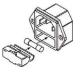
natural_image
Technical line drawing of a mechanical component with two connectors (no text or symbols)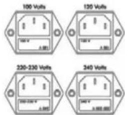
Input:
220 - 230 V\~
240 V\~
50 - 60 Hz
Max. Power
Consumption
440 Watts
Replacing fuses only to be carried out by qualified service personnel! Replace fuses only with type and rating shown below:
Setting: 220 - 230 V
→ Fuse: 250 V/T 1.6 A
Setting: 240 V
→ Fuse: 250 V/T 1.6 A
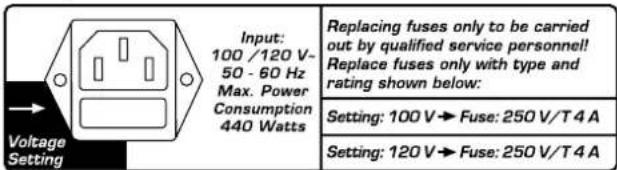
HEAD / COMBO 100

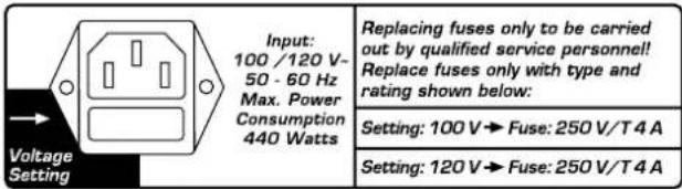
Input: 100 / 120 V-50 - 60 Hz Max. Power Consumption 440 Watts
Replacing fuses only to be carried out by qualified service personnel! Replace fuses only with type and rating shown below:
Setting: 100 V→Fuse: 250 V/T 4 A
Setting: 120 V→Fuse: 250 V/T4 A
| Voltage Setting | Input:220 - 230 V-240 V-50 - 60 HzMax. Power Consumption290 Watts | Replacing fuses only to be carried out by qualified service personnel!Replace fuses only with type and rating shown below: |
| Setting: 220 - 230 V→Fuse: 250 V/T 1A | ||
| Setting: 240 V→Fuse: 250 V/T 1A |
COMBO 50
| Voltage Setting | Input:100/120 V-50 - 60 HzMax. Power Consumption290 Watts | Replacing fuses only to be carried out by qualified service personnel!Replace fuses only with type and rating shown below: |
| Setting: 100 V→Fuse: 250 V/T 2 A | ||
| Setting: 120 V→Fuse: 250 V/T 2 A |
Switchblade is connected
properly, but no sound is audible.
- The guitar's VOLUME knob is turned all the way down.
• The amp is set to STANDBY. - The amp's VOLUME knob is turned all the way down.
- The effects loop is active and set to SERIAL, but no effect device is connected.
- The anode fuse has blown. Ensure that it is replaced with a fuse of the same rating.
- The fuse for the tube heating tripped (the tubes don't glow). Ensure that it is replaced with a fuse bearing the same rating.
The amp makes ringing noises
when played and tends to Feedback.
- One or several tubes are microphonic. Replace the defective tube with another of the same type.
Signs of tube wear such as increased microphonics and noise, Treble loss, weak power output or muddy sound begin reappearing just a few hours after replacing tubes.
- The wrong tubes were installed when old tubes were replaced or the amp was not biased properly. Take the amp to a professional to correct the problem.
The sound is washed out or muddy when you switch an effects processor on.
- The signal processor provides a wet signal that is blended with the dry or original signal. Depending on the type of effect, the processor may be returning a dry signal back along with wet signal, which causes phase cancellations when mixed to the dry signal in Switchblade's Parallel loop. To prevent this, set the effects loop to SERIAL or turn the dry signal all the way down on the signal processor.
9 Technical Specifications
All level indications relate to 0 dBV (1V RMS).
9.1 Inputs
| INSTRUMENT Input |
| Input: 6.3 mm (1/4") jack |
| Type: unbalanced |
| Input impedance: 1 M ohms |
| Sensitivity: -50 dB (Clean Channel) |
| Max. Input Level: 0 dB |
FX Return
| Input: 6.3 mm (1/4") jack |
| Type: unbalanced |
| Input impedance: 48 k ohms |
| Max. sensitivity: -10 dB button engaged: -21 dB, disengaged: -11 dB |
| Max. Input Level: -10dB button engaged: +0 dB, disengaged +10 dB |
MIDI IN
| Port: DIN 45 329 (7-pin) |
| Data reception: Program change data, Tap Delay function |
| Channels: 16, Omni mode |
| Power supply: 15V DC max. 200mA, pin 6 = positive, pin 7 = negative |
9.2 Outputs
| FX Send | |
| Output: 6.3 mm (1/4") jack | |
| Type: unbalanced | |
| Output impedance: 2.2 k ohms | |
| Output Level: +3 dB | |
| Max. output Level: -10dB button engaged: -2 dB, disengaged: +8 dB |
MIDI THRU
| Port: DIN 45 328 (5-pin) | |
| Data handling: | All data sent to MIDI IN are patched out unchanged. |
Speaker Outputs
| 6.3 mm (1/4") jacks: | 1 x 4 ohms, 2 x 16 ohms / 1 x 8 ohms, |
| 1 x 16 ohms |
Speaker
| 100 Combo | 2 x 12 ^ Eminence ^ Rockdriver 60 |
| 50 Combo | 1 x 12 ^ Eminence ^ Rockdriver 60 |
9.3 General Electrical Data
| Switchblade 100 Head/Combo | Switchblade 50 Combo |
| Max. current consumption: | |
| 440 watts | 290 watts |
Max. power consumption:
| 1.75A @ 240 volts 0.97A @ 240 volts |
| 1.89A @ 220-230 volts 1.07A @ 220-230 volts |
| 3.50A @ 117-120 volts 2.00A @ 117-120 volts |
| 3.95A @ 100 volts 2.15A @ 100 volts |
Mains voltage tolerance range: +/- 10 %
| External fuses (anode): | |
| 1 x T 630 mA | 1 x T 400 mA |
Internal fuses:
| 1 x TT 10 A super slow blow | 1 x TT 10 A super slow blow |
| 2 x T 630 mA | 2 x T 630 mA |
Mains fuse (5 x 20 mm):
| Europe: (variable: 220 V-230 V / 240 V) | |
| 1 x 250 V / T 1.6 A | 1 x 250 V / T 1 A |
| USA/Canada/Asia: (variable: 100 V / 120 V) | |
| 1 x 250 V / T 4 A | 1 x 250 V / T 2 A |
Ambient operating temperature range:
| 0 °C to + 35 °C | 0 °C to + 35 °C |
9.4 General Mechanical Data
| 100 Head | 100 Combo | 50 Combo | |
| Dimensions: (including corners, handles, feet) | |||
| Width: | 750 mm | 647 mm | 600 mm |
| Height: 280 mm | 500 mm | 500 mm | |
| Depth: | 258 mm | 285 mm | 285 mm |
| Weight: | 17.6 kg | 30.3 kg | 22.8 kg |

Prefacio
Head y Combo
$$ R = (R 1 \times R 2) / (R 1 + R 2) $$
$$ R = (8 \times 1 6) / (8 + 1 6) $$
$$ R = 1 2 8 / 2 4 $$
$$ R = 5, 3 3 $$
HEAD / COMBO 100


COMBO 50

Head et Combo
5.1 EFFETS ON/OFF
$$ R = (R 1 \times R 2) / (R 1 + R 2) $$
$$ R = (8 \times 1 6) / (8 + 1 6) $$
$$ R = 1 2 8 / 2 4 $$
$$ R = 5, 3 3 $$
HEAD / COMBO 100

COMBO 50

5.2 CHANNEL SELECT
$$ R = (R 1 \times R 2) / (R 1 + R 2) $$
$$ R = 1 2 8 / 2 4 $$
$$ R = 5, 3 3 $$
HEAD / COMBO 100

COMBO 50

- Read all of these instructions!
- Save these instructions for later use!
• Follow all warnings and instructions marked on the product! - Do not use this product near water, i.e. bathtub, sink, swimming pool, wet basement, etc.
- Do not place this product on an unstable cart, stand or table. The product may fall, causing serious damage to the product or to persons!
- Slots and openings in the cabinet and the back or bottom are provided for ventilation; to ensure reliable operation of the product and to protect it from overheating, these openings must not be blocked or covered. This product should not be placed in a built-in installation unless proper ventilation is provided.
- This product should not be placed near a source of heat such as a stove, radiator, or another heat producing amplifier.
- Use only the supplied power supply or power cord. If you are not sure of the type of power available, consult your dealer or local power company.
- Do not allow anything to rest on the power cord. Do not locate this product where persons will walk on the cord.
- Never break off the ground pin on the power supply cord.
- Power supply cords should always be handled carefully. Periodically check cords for cuts or sign of stress, especially at the plug and the point where the cord exits the unit.
- The power supply cord should be unplugged when the unit is to be unused for long periods of Time.
• If this product is to be mounted in an equipment rack, rear support should be provided. - This product should be used only with a cart or stand that is recommended by Hughes & Kettner.
- Never push objects of any kind into this product through cabinet slots as they may touch dangerous voltage points or short out parts that could result in risk of fire or electric shock. Never spill liquid of any kind on the product.
- Do not attempt to service this product yourself, as opening or removing covers may expose you to dangerous voltage points or other risks. Refer all servicing to qualified service personnel.
• Clean only with dry cloth. - Do not defeat the safety purpose of the polarized or grounding-type plug. A polarized plug has two blades with one wider than the other. A grounding type plug has two blades and a third grounding prong. The wide blade or the third prong are provided for the safety. If the provided plug does not fit into your outlet, consult an electrician for replacement of the obsolete outlet.
- Unplug this product from the wall outlet and refer servicing to qualified service personnel under the following conditions:
• When the power cord or plug is damaged or frayed.
• If liquid has been spilled into the product.
• If the product has been exposed to rain or water.
• If the product does not operate normally when the operating instructions are followed.
• If the product has been dropped or the cabinet has been damaged.
• If the product exhibits a distinct change in performance, indicating a need of service! - Adjust only these controls that are covered by the operating instructions since Improper
adjustment of other controls may result in damage and will often require extensive work by a qualified technician to reStore the product to normal operation.
• Exposure to extremely high noise Levels may cause a permanent hearing loss. - Individuals vary considerably in susceptibility to noise induced hearing loss, but nearly everyone will lose some hearing if exposed to sufficiently intense noise for a sufficient Time. The U.S. Government's Occupational Safety and Health Administration (OSHA) has specified the following permissible noise Level exposures:
- According to OSHA, any exposure in excess of the above permissible limits could result in some hearing loss.
- Ear plug protectors in the ear canals or over the ears must be worn when operating this amplification system. In order to prevent a permanent hearing loss if exposure is in excess of the limits as set forth above. To ensure aGainst potentially dangerous exposure to high sound pressure Levels, it is recommended that all persons exposed to equipment capable of producing high sound pressure Levels such as this amplification system be protected by hearing protectors while this unit is in operation.
- Fuses: Replace with IEC 127 (5 x 20 mms) type and rated fuse for best performance only
Duration Per Day In Hours Sound Level dBA, Slow Response
| 8 90 | |
| 6 92 | |
| 4 95 | |
| 3 97 | |
| 2 100 | |
| 1^1/2 102 | |
| 1 105 | |
| ^1/2 110 |
¼ or less 115
TO PREVENT THE RISK OF FIRE AND SHOCK HAZARD, DO NOT EXPOSE THIS APPLIANCE TO MOISTURE OR RAIN. DO NOT OPEN CASE; NO USER SERVICE-ABLE PARTS INSIDE. REFER SERVICING TO QUALIFIED SERVICE PERSONNEL.
PLEASE READ BEFORE USE AND KEEP FOR LATER USE!
- The unit has been built by Hughes & Kettner In accordance with IEC 60065 and left the factory in safe working order. To maintain this condition and ensure non-risk operation, the user must follow the advice and warning comments found in the operating instructions. The unit conforms to Protection Class I (protectively earthed).
HUGHES & KETTNER ONLY GUARANTEES THE
SAFETY, RELIABILITY AND EFFICIENCY OF THE UNIT IF:
• Assembly, extension, re-adjustment, modifications or repairs are carried out by Hughes & Kettner or by persons authorized to do so.
- The electrical installation of the relevant area complies with the requirements of IEC (ANSI) specifications.
• The unit is used in accordance with the operating instructions.
• The unit is regularly checked and tested for electrical safety by a competent technician.
WARNING:
- If covers are opened or sections of casing are removed, except where this can be done manually, live parts can become exposed.
- If it is necessary to open the unit this must be Isolated from all power sources. Please take this into account before carrying out adjustments, maintenance, repairs and before replacing parts.
- The appliance can only be insulated from all power sources if the Mains connection is unplugged.
- Adjustment, maintenance and repairs carried out when the unit has been opened and is still live may only be performed by specialist personnel who are authorized by the manufacturer (In accordance with VBG 4) and who are aware of the associated hazards.
- Loudspeaker Outputs which have the IEC 417/5036 symbol (Diagram 1, below) can carry voltages which are hazardous if they are made contact with. Before the unit is switched on, the loudspeaker should therefore only be connected using the Lead recommended by the manufacturer.
- Where possible, all plugs on connection cables must be screwed or locked onto the casing.
- Replace fuses only with IEC 127 type and specified rating.
- It is not permitted to use repaired fuses or to short-circuit the fuse holder.
- Never interrupt the protective conductor connection.
- Surfaces which are equipped with the „HOT“ mark (Diagram 2, below), rear panels or covers with cooling slits, cooling bodies and their covers, as well as tubes and their covers are purposely designed to dissipate high temperatures and should therefore not be touched.
- High loudspeaker Levels can cause permanent hearing damage. You should therefore avoid the Direct vicinity of loudSpeakers operating at high Levels. Wear hearing protection if continuously exposed to high Levels.
Mains CONNECTION:
• The unit is designed for continuous operation.
• The set operating voltage must match the local Mains supply voltage.
- Caution: The unit Mains switch must be in position OFF before the Mains cable is connected.
• The unit is connected to the Mains via the supplied power unit or power cable.
• Power unit: Never use a damaged connection Lead. Any damage must be rectified by a competent technician.
- Avoid connection to the Mains supply in distributor boxes together with several other power consumers.
- The plug socket for the power supply must be positioned near the unit and must be easily
accessible
PLACE OF INSTALLATION:
- The unit should stand only on a Clean, horizontal working surface.
• The unit must not be exposed to vibrations during operation. - Keep away from moisture and dust where possible.
- Do not place the unit near water, baths, wash basins, kitchen sinks, wet areas, swimming pools or damp rooms. Do not place objects containing liquid on the unit - vases, glasses, bottles etc.
- Ensure that the unit is well ventilated.
- Any ventilation openings must never be blocked or covered. The unit must be positioned at least 20 cm away from walls. The unit may only be fitted in a rack if adequate ventilation is ensured and if the manufacturer's installation instructions are followed.
- Keep away from Direct sunlight and the immediate vicinity of heating elements and radiant heaters or similar devices.
- If the unit is suddenly moved from a cold to a warm location, condensation can form inside it. This must be taken into account particularly in the case of tube units. Before switching on, wait until the unit has reached room temperature.
- Accessories: Do not place the unit on an unsteady trolley, stand, tripod, base or table. If the unit falls Down, it can cause personal injury and itself become damaged. Use the unit only with the trolley, rack stand, tripod or base recommended by the manufacturer or purchased together with the unit. When setting the unit up, all the manufacturer's instructions must be followed and the setup accessories recommended by the manufacturer must be used. Any combination of unit and stand must be moved carefully. A sudden stop, excessive use of force and uneven floors can cause the combination of unit and stand to tip over.
• Additional equipment: Never use additional equipment which has not been recommended by the manufacturer as this can cause accidents.
• To protect the unit during bad weather or when left unattended for prolonged periods, the Mains plug should be disconnected. This prevents the unit being damaged by lightning and power surges in the AC Mains supply.
Diagram 1 Diagram 2


This is to certify that
Hughes & Kettner Switchblade
complies with the provisions of the Directive of the Council of the European Communities on the approximation of the laws of the Member States relating to electromagnetic compatibility (EMC Directive 89/336/EEC) and the low voltage Directive (73/23/EEC). This declaration of conformity of the European Communities is the result of an examination carried out by the Quality Assurance Department of STAMER GmbH in accordance with European Standards EN 50081-1. EN 50082-1 and EN 60065 for low voltage, as laid down in Article 10 of the EMC Directive.
Stein
International Inquiries:
Fax: +49 - 68 51 - 905 200
hkinternational@hughes-and-kettner.com
www.hughes-and-kettner.com
Copyright 2006 by Music & Sales GmbH
Subject to change without notice