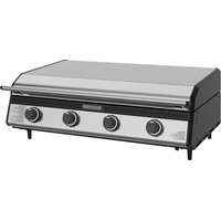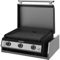
6029 - Grill plate Blackstone - Free user manual and instructions
Find the device manual for free 6029 Blackstone in PDF.


User questions about 6029 Blackstone
0 question about this device. Answer the ones you know or ask your own.
Ask a new question about this device
Download the instructions for your Grill plate in PDF format for free! Find your manual 6029 - Blackstone and take your electronic device back in hand. On this page are published all the documents necessary for the use of your device. 6029 by Blackstone.
USER MANUAL 6029 Blackstone
natural_image
Technical line drawing of a server rack with three circular ports and a hanging control unit (no text or symbols)OWNER'S MANUAL
28" XL GRIDDLE DROP-IN WITH HOOD AND INSULATING JACKET
TABLE OF CONTENTS
IMPORTANT SAFETY INFORMATION ....02
ACTIVATE YOUR WARRANTY 03
ASSEMBLY GUIDE 04
USING YOUR BLACKSTONE....11
TROUBLESHOOTING 18
IMPORTANT:
This instruction manual contains important information necessary for the proper assembly and safe use of the appliance.
Read and follow all warnings and instructions before assembling and using the appliance.
Follow all warnings and instructions when using the appliance.
Keep this manual for future reference.
Installer/Assembler: Leave these instructions with the consumer.

For the latest version of this manual, scan this code or visit
BlackstoneProducts.com/support
SAFETY ALERT KEY
! DANGER
Indicates a hazardous situation that, if not avoided, will result in death or serious injury.
CAUTION
Indicates a hazardous situation that, if not avoided, could result in minor or moderate injury.
WARNING
Indicates a hazardous situation that, if not avoided, could result in death or serious injury.
NOTICE
Indicates information considered important, but not hazard-related (e.g. messages related to property damage).
IMPORTANT SAFETY INFORMATION
DANGER
If you smell gas:
- Shut off gas to the appliance.
- Extinguish any open flame.
- Open hood.
- If odor continues, keep away from the appliance and immediately call your gas supplier or your fire department.
Failure to follow these instructions could result in fire or property damage, personal injury or death.
DANGER
- NEVER operate this appliance unattended.
- If a fire should occur, keep away from the appliance and immediately call your fire department. DO NOT attempt to extinguish an oil or a grease fire with water.
Failure to follow these instructions could result in fire or property damage, personal injury or death.
ELECTRIC APPLIANCE SAFETY
TO PROTECT AGAINST ELECTRIC SHOCK:
- DO NOT immerse cord or plugs in water or other liquid.
- Unplug from the outlet when not in use and before cleaning. Allow to cool before putting on or taking off parts.
- DO NOT use an outdoor cooking gas appliance for purposes other than intended.
- DO NOT operate this appliance with a damaged cord, plug, or after the appliance malfunctions or has been damaged in any manner. Contact the manufacturer for repair.
- DO NOT let the cord hang over the edge of a table or touch hot surfaces.
- Keep any electrical supply cord and the fuel supply hose away from heated surfaces.
- When connecting, first connect plug to the appliance then into the outlet.
USE ONLY A GROUND FAULT INTERRUPTER (GFI) PROTECTED CIRCUIT WITH THIS APPLIANCE.
- This appliance, when installed, must be electrically grounded in accordance with local codes or, in the absence of local codes, with NFPA 70 Canadian Electrical Code, Part I.
- DO NOT remove the grounding plug or use with an adapter of 2 prongs.
- Use only extension cords with a 3 prong grounding plug, rated for the power of the equipment, and approved for outdoor use with a W-A marking.
WARNING
- DO NOT store or use gasoline or other flammable liquids or vapors in the vicinity of this or any other appliance.
- An LPG cylinder not connected for use shall not be stored in the vicinity of this or any other appliance.
GAS APPLIANCE SAFETY
- The use of alcohol, prescription, or non-prescription drugs may impair the consumer's ability to properly assemble or safely operate the appliance.
- Keep children and pets away from the appliance at all times.
- Have a type BC or ABC fire extinguisher readily available.
DO NOT USE FOR PURPOSES OTHER THAN INTENDED:
- DO NOT use for commercial cooking.
- DO NOT use this appliance as a heater.
WARNING
Improper installation, use, adjustment, alteration, service, modification, or maintenance can cause injury or property damage. Refer to this manual.
INSTALLATION MUST CONFORM WITH LOCAL CODES
In the absence of local codes, installation must conform with either ANSI Z223.1/NFPA 54, CSA B149.1, or CSA B149.2.
ACTIVATE YOUR WARRANTY
The North Atlantic Imports LLC 1-Year Warranty covers replacement parts up to one year after the date of purchase.
TO ENABLE THIS WARRANTY, YOU WILL NEED TO PROVIDE:
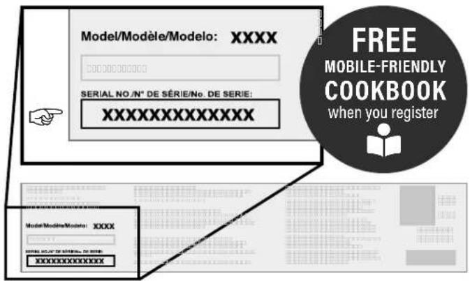
Your appliance's Serial Number
text_image
Model/Modèle/Modelo: XXXX 00000000000 SERIAL NO./N° DE SÉRIE/No. DE SERIE: XXXXXXXXXXXXXX FREE MOBILE-FRIENDLY COOKBOOK when you register Model/Modèle/Modelo: XXXX SERIAL NO./N° DE SÉRIE/No. DE SERIE: XXXXXXXXXXXXXXThe Serial Number can be found on your appliance's Manufacturer Label.
(The Manufacturer Label is a large silver sticker found on the body of your appliance.)

Register your appliance at BlackstoneProducts.com/register
WARRANTY OVERVIEW
North Atlantic Imports, the manufacturer, will warranty for one year from purchase all parts, workmanship, and finishes. It will be the manufacturer's option as to whether to repair or replace any of the above items. All warranties are limited to the original purchaser only. This warranty does not cover any liability on the part of North Atlantic Imports, its agents or employees, for any indirect or consequential damages for breach of warranty. The purchaser must follow the manufacturer's usage instructions.
Under no circumstances is the manufacturer responsible for damages from the failure to operate the cooking station properly. It is the responsibility of the purchaser to establish the warranty period by verifying the original purchase date with original sales receipt.
DETAILED EXPLANATION OF THE WARRANTY
North Atlantic Imports LLC warrants to the owner that the product covered by this agreement is free from defects in material and workmanship under normal use and service for which it was intended if, but only if, it has been operated in accordance with North Atlantic Imports LLC instructions exclusively for domestic use, and not for private or public club, institutional or commercial purposes.
North Atlantic Imports LLC's obligation under this warranty is limited to replacing or repairing, free of charge, any part or parts that may prove, to the satisfaction of North Atlantic Imports LLC, to be defective under normal home use and service within the following stated periods of time from the date of purchase; for one year from purchase, all parts, finish, and workmanship. Should any failure to conform to this warranty become apparent during applicable warranty periods stated above, the original purchaser must notify North Atlantic Imports LLC of breach of warranty within the applicable warranty period.
North Atlantic Imports LLC shall upon notice and compliance by the original purchaser with such instructions, correct such nonconformity by repair or replacement of the defective part or parts.
Correction in the manner provided above shall constitute a fulfillment of all obligations of North Atlantic Imports LLC with respect to the quality of the product.
North Atlantic Imports LLC does not warrant this equipment to meet the requirement of any safety code of any state, municipality or other jurisdiction, and the original purchaser assumes all risk and liability whatsoever resulting from the use thereof, whether used in accordance with North Atlantic Imports LLC instructions or otherwise.
This warranty does not cover and is intended to exclude any liability on the part of North Atlantic its agents, servants or employees whether under this warranty or implied by law for any indirect or consequential damages for breach on any warranty. The purchaser must establish all applicable warranty periods pursuant to this warranty by verifying the original purchase date by producing the dated sales receipt. This warranty shall not apply to this product or any other part thereof which has been subject to accident, negligence, alteration, abuse, or misuse or which has been repaired or altered without North Atlantic written consent, outside of North Atlantic Imports LLC factory. The full manufacturer warranty is not valid for griddles purchased from unlicensed, third-party resellers, purchased at a discount due to missing or damaged parts, or purchased as a floor model; at the discretion of North Atlantic Imports.
North Atlantic Imports LLC makes no warranty whatsoever in respect to accessories or parts not supplied with it. This warranty shall apply only within the boundaries of the United States of America and Canada. This warranty gives the original purchaser specific rights, and the original purchaser may also have other rights, which vary from state to state.

ASSEMBLY GUIDE
EXPLODED VIEW

text_image
Exploded view diagram of a blackstone refrigerator with numbered parts for identificationPARTS LIST
1 Griddle body (1 piece)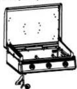 | 2 Griddle top (1 piece)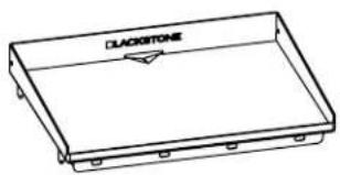 | 3 Hood handle (1 piece)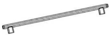 | |||
4 Jacket base outer panel (1 piece)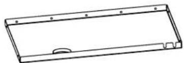 | 5 Jacket base inner panel (1 piece)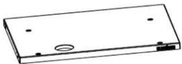 | 6 Jacket rear inner panel (1 piece)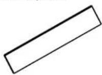 | 7 Jacket rear outer panel (1 piece)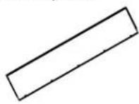 | ||
8 Jacket left inner panel (1 piece)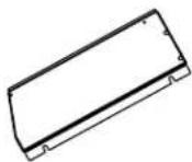 | 9 Jacket left outer panel (1 piece)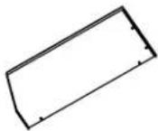 | 10 Jacket right inner panel (1 piece)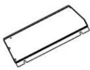 | 11 Jacket right outer panel (1 piece)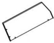 | 12 Jacket silicone sleeve (1 piece)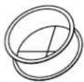 | 13 Hat channels (2 pieces)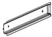 |
14 Mica washers (2 pieces)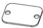 | 15 Grease cup (1 piece)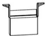 | 16 Control knobs (3 pieces) | 17 Feet (4 pieces)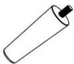 | 18 PCB box (1 piece)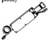 | 19 Match holder (1 piece)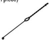 |
20 Hardware pack (1 piece)
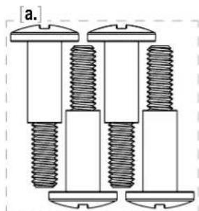
a. M6 shoulder bolts (4 pieces)
b. M6x15 screws (5 pieces)
c. M6x35 screws (4 pieces)
d. M6x45 screws (4 pieces)
natural_image
Three identical mechanical bolts arranged in a row, no text or symbols visible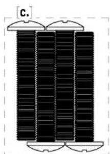
natural_image
Diagram of three vertical cylindrical objects with curved top caps, no text or symbols present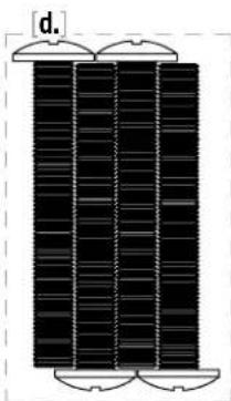
natural_image
Pure diagram of three vertical panels with curved top elements, no text or symbols present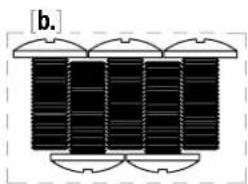
natural_image
Diagram of four vertical cylindrical objects with curved top caps, arranged in a row (no text or symbols)ASSEMBLY INSTRUCTIONS
Find a large, clean area to assemble your appliance.
Remove all packing material before assembling.
CAUTION
Sharp edges. Wear gloves while assembling.
CAUTION
Heavy pieces. Two people should assemble this appliance.
natural_image
Line drawing of a cylindrical mechanical component with a central hub and two side connectors (no text or symbols)
NOT INCLUDED:
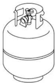
LPG cylinder
Size: 18 x 12 in (45 x 30 cm), 20 lb (9 kg)
LPG cylinder must include collar to protect LPG cylinder valve.
TOOL NEEDED:
Phillips head screwdriver
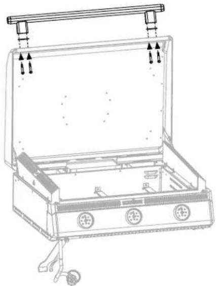
STEP 01 Use four (4) M6 shoulder bolts [a.] to attach the handle and hood handle standoff and two (2) mica washers to the front of the hood.
[a.] × 4
natural_image
Line drawing of an open electrical switchgear box with mounting holes and a handle (no text or symbols)STEP 03 Install the three (3) control knobs by pushing them into place in the OFF position.
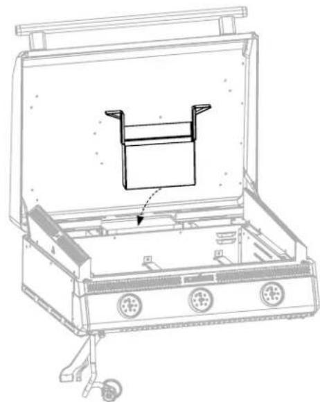
STEP 02 Slide the grease cup into the holder on the back of the griddle body.
natural_image
Technical line drawing of an open electrical enclosure with internal components and a handle (no text or symbols)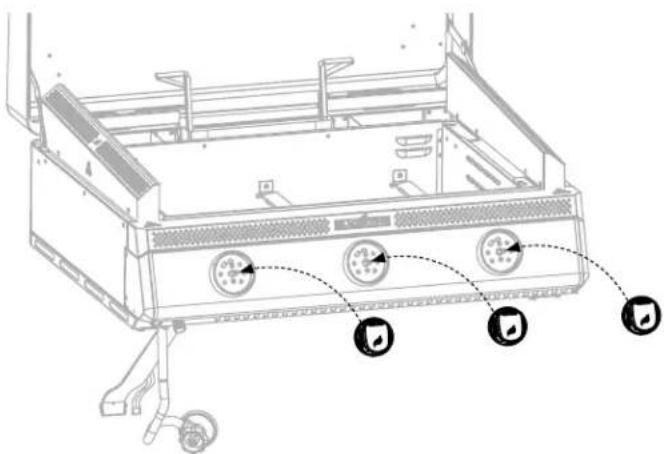
text_image
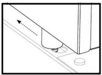
Technical diagram of a front-mounted air conditioner unit with labeled control buttons and indicator lightsSTEP 04 Remove the four (4) protective washers from the griddle foot pins. With the help of another person, place the griddle top onto the griddle body by aligning the four foot pins to the holes on top of the unit.
Make sure the front pins are fully seated in the holes, then push the griddle top back to lock the griddle in place.
natural_image
Pure technical diagram showing a mechanical component with no text, numbers, or symbols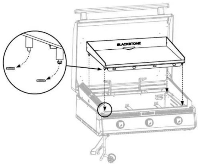
text_image
BLACKSTONEOPTION A: INSTALL AS DROP-IN WITH INSULATING JACKET
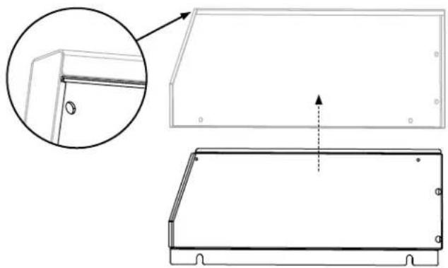
STEP 01 Slide the jacket left inner panel into the jacket left outer panel.
natural_image
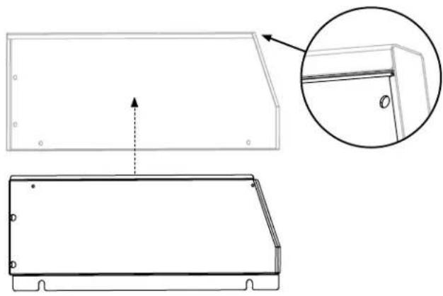
Technical line drawing of a rectangular frame with an inset magnified detail showing a corner detail (no text or symbols)STEP 02 Slide the jacket right inner panel into the jacket right outer panel.
natural_image
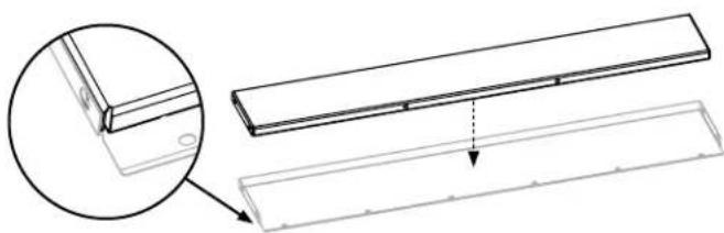
Technical line drawing of a rectangular frame with an inset close-up showing a detail (no text or symbols)STEP 03 Place the jacket rear inner panel into the jacket rear outer panel.
natural_image
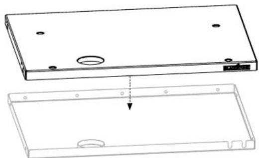
Technical line drawing of a mechanical component with an inset magnified detail (no text or symbols)STEP 04 Place the jacket outer base panel onto the jacket inner base panel.
natural_image
Technical line drawing of a rectangular electronic enclosure with mounting holes and a side view showing internal components (no text or symbols)STEP 05 Use four (4) M6x35 screws [c.] to attach the left and right jacket panel assemblies to the jacket base panel assembly.
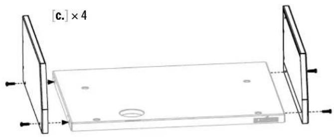
natural_image
Technical line drawing of a rectangular plate with mounting holes and a central circular hole, shown without any text or symbols.STEP 06 Use five (5) M6x15 screws [b.] to attach the rear jacket panel assembly to the jacket base panel assembly.
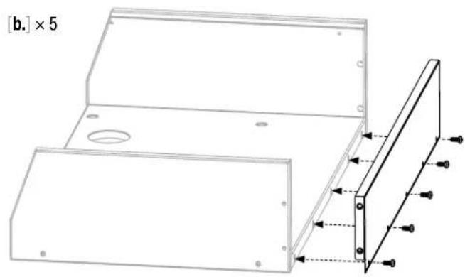
natural_image
Technical drawing of a metal bracket with mounting holes and a side view showing internal components (no text or symbols)STEP 07 Use four (4) M6x45 screws [d.] to secure the rear jacket panel to the left and right jacket panel assemblies. Slide the jacket silicon sleeve into the jacket base panel assembly.
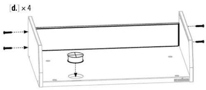
text_image
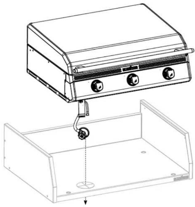
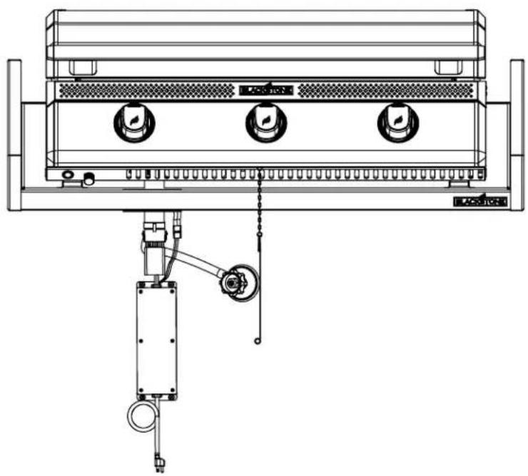
[d.] × 4STEP 08 With the help of another person, direct the regulator hose and electric wires through the jacket silicon sleeve and place the griddle body onto the jacket base panel assembly.
natural_image
Technical line drawing of a portable appliance with control panel and mounting bracket (no text or symbols)STEP 09 Push the 18P male and female connector together.
② press the yellow clip to lock the connector.
●ash the 3P male and female connector together.
Note: the PCB box must be permanently attached to the cabinet.
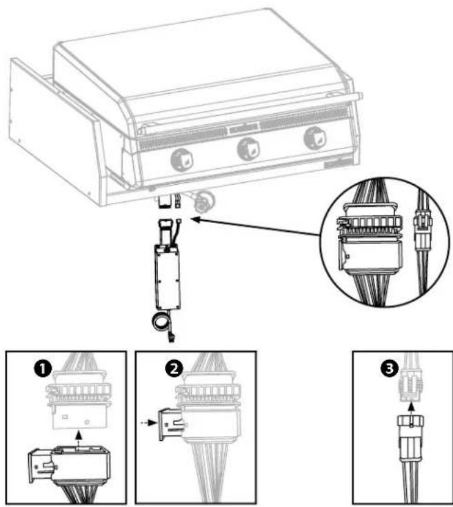
text_image
Technical diagram showing assembly steps of a device with labeled components and exploded viewsSTEP 10 Remove the self-tapping screw from the griddle body and use it to attach the match holder.
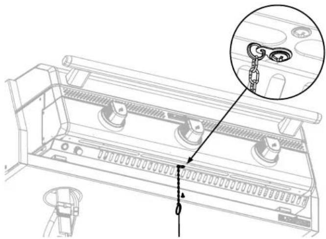
natural_image
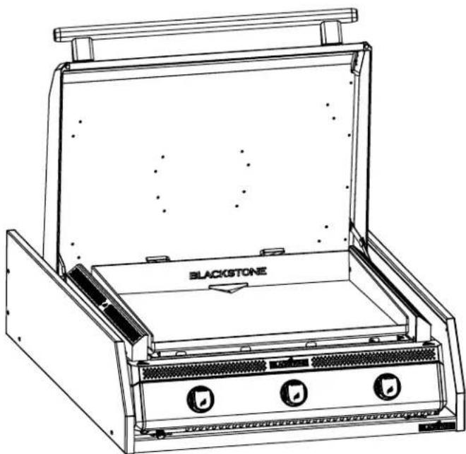
Technical line drawing of a mechanical device with a magnified inset showing a chain link (no text or symbols)STEP 11 Proceed to USING YOUR BLACKSTONE.

natural_image
Line drawing of a blackstone appliance with three buttons and ventilation slots (no text or symbols)| NOTICE |
| DO NOT leave the hood closed for more than 10 minutes while cooking. |
| NOTICE |
| The insulating jacket must be permanently secured to cabinet. |
Grease cup liner required for use.
OPTION B: FOR NON-COMBUSTIBLE COUNTERTOP USE
STEP 01 Unscrew the four (4) M6 screws from the hat channels. Screw the four (4) feet through the hat channels and into the base.
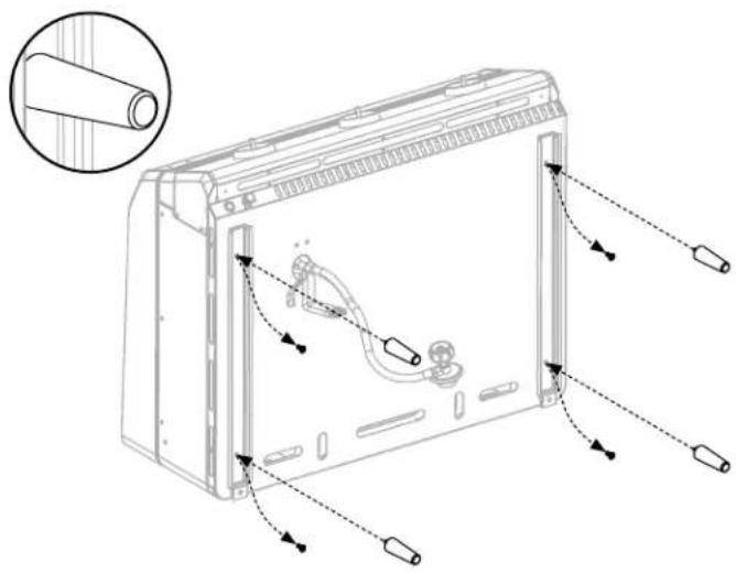
natural_image
Technical line drawing of a device rear panel with cable routing and component labels (no text or symbols)STEP 02 With the help of another person, set on counter. Hose and cables MUST be routed through the left side. Proceed to USING YOUR BLACKSTONE.
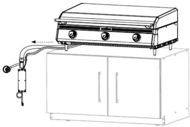
natural_image
Line drawing of a portable stove mounted on a cabinet, with hoses and control valves (no text or symbols)NOTICE
DO NOT leave the hood closed for more than 10 minutes while cooking.
NOTICE
The included feet MUST be used when griddle is in the tabletop configuration.
DO NOT operate this appliance any closer than 36 in (1 m) from the sides and back of the appliance to combustible construction.
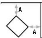
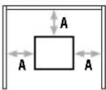
WITHOUT JACKET
A: 36 in (1 m)
WARNING
The cabinet CAN NOT store 2 or more LPG cylinders.
USING YOUR BLACKSTONE
BEFORE COOKING CHECK BURNERS
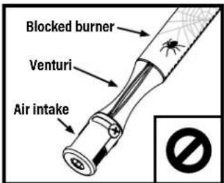
Before connection, ensure that there is no debris caught in the head of the gas cylinder, regulator, burner and burner ports.
Spiders and insects can nest within and clog the burner/venturi tube at the orifice.
Please reference the Troubleshooting chapter for burner cleaning instructions.
text_image
Blocked burner Venturi Air intakeWARNING
A clogged burner can lead to a fire beneath the appliance.
Burner should be removed and cleaned whenever blockages are found.
text_image
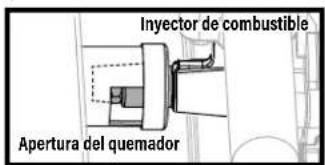
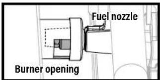
Fuel nozzle Burner opening⚠ Ensure that the gas rail fuel nozzle orifice is correctly engaged within the burner opening.
DANGER
Flammable items can spontaneously combust if placed near the appliance.
DO NOT place flammable items such as aerosol containers, oily or greasy towels near the cooking surface.
Keep the outdoor cooking gas appliance area clear and free from combustible materials, gasoline and other flammable vapors and liquids.
THE MINIMUM AMBIENT OPERATING TEMPERATURE IS 0°F (-18°C).
BUILT-IN INSTALLATION
- DO NOT install this appliance under overhead combustible surfaces. If installed under overhead combustible construction, the appliance must be installed in conjunction with a suitable UL710 or ULC S646 approved heavy duty vent hood only.
- For installation in a built-in enclosure constructed of combustible materials when installed with the included insulating jacket.
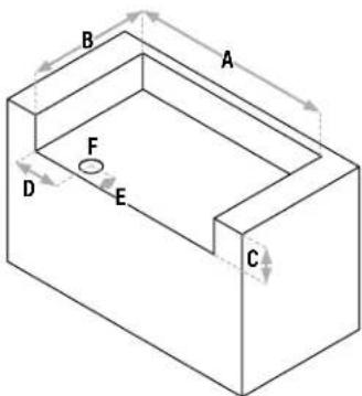
text_image
B A F D E CCAVITY MINIMUM DIMENSIONS
A: Width = 38.75 in
B: Depth = 27.5 in
C: Height = 8 in
(>8 in will cause hood interference)
HOLE MINIMUM DIMENSIONS
D: Distance from side = 10.5 in
E: Distance from front = 3.75 in
F: Diameter = 4.5 in
SETTING UP YOUR OUTDOOR SPACE THIS APPLIANCE MUST ONLY BE USED OUTDOORS.
- DO NOT use this appliance inside buildings, garages, or any other enclosed area.
- DO NOT install this appliance in or on a boat.
- DO NOT install this appliance in or on a recreational vehicle.
MAINTAIN PROPER CLEARANCES FROM COMBUSTIBLE MATERIAL.
- DO NOT use this appliance on or under any apartment or condominium balcony or deck.
- DO NOT obstruct the flow of combustion and ventilation air.
- DO NOT operate this appliance any closer than 80in(150m) from the from the sides and back of the appliance to vertical combustible construction.
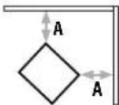
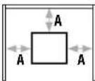
WITH JACKET A: 6 in (150 mm)
WARNING
The cabinet CAN NOT store 2 or more LPG cylinders.
SHELTERED OUTDOOR AREAS:
All openings must be permanently open; sliding doors, garage doors, windows or screened openings are not considered as permanent openings.
An appliance is considered to be outdoors if installed with shelter no more inclusive than:
a. With walls on three sides, but with no overhead cover.
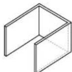
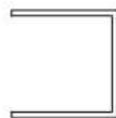
b. Within a partial enclosure that includes an overhead cover and no more than two sidewalls. The sidewalls may be parallel, as in a breezeway, or at right angles to each other.
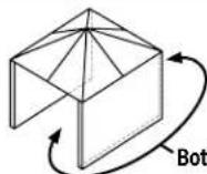
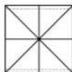
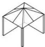
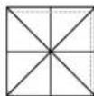
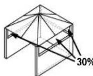
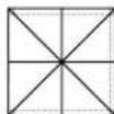
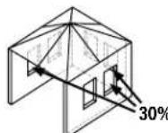
c. Within a partial enclosure that includes an overhead cover and three sidewalls, as long as 30% or more of the horizontal periphery of the enclosure is permanently open.
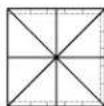
LPG CYLINDER REQUIREMENTS ONLY USE A 20 LB (9 KG) CYLINDER
- The LPG supply cylinder to be used must be constructed and marked in accordance with the specifications for LP gas cylinders, U.S. Department of Transportation (DOT) or the Standard for Cylinders, Spheres and Tubes for the Transportation of Dangerous Goods, CAN/CSA-B339.
- Only LPG cylinders marked "propane" shall be used.
- The LPG cylinder supply system must be arranged for vapor withdrawal.
- Always keep new LPG cylinders in upright position during use, transit or storage.
- Always keep the ventilation opening(s) of the cylinder enclosure free and clear from debris.
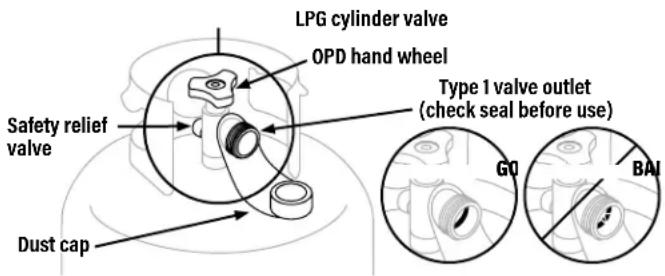
THE LPG CYLINDER VALVE MUST HAVE:
- Type 1 valve outlet (thread on the outside).
- Safety relief valve.
- UL listed Overfill Protection Device (OPD). This OPD safety feature is identified by a unique triangular hand wheel.
- Dust cap.
text_image
LPG cylinder valve OPD hand wheel Type 1 valve outlet (check seal before use) Safety relief valve G0 BAI Dust capThe seal on the type 1 valve outlet could, over time, show marked and visible damage or deterioration that might cause a leak even with the connection tightened.
- A visual inspection for the seal must be carried out every time a LPG cylinder is replace or refilled.
- Any LPG cylinder showing signs of damage or deterioration as those illustrated including visible cracks and pitting, must be returned unused to the seller.
STORING LPG CYLINDERS
WARNING
- DO NOT store a spare LPG cylinder under or near this appliance.
- DO NOT fill an LPG cylinder beyond 80% full.
If the information above is not followed exactly, a fire causing death or serious injury may occur.
- The LPG cylinder must be turned OFF when the appliance is not in use.
- LPG cylinders must be stored outdoors and out of the reach of children.
- DO NOT store an LPG cylinder inside a building, garage, or any other enclosed area.
FILLING & EXCHANGE
- Use only those reputable exchange companies that inspect, precision fill, test and certify their cylinders. LPG dealer must purge new cylinder before filling.
• Volume of propane in cylinder will vary by temperature.
WARNING
A frosty regulator indicates gas overfill. Immediately close LPG cylinder valve and call local LPG dealer for assistance.
- DO NOT release liquid petroleum gas (LPG) into the atmosphere.
- To remove gas from LPG cylinder, contact a certified LPG dealer or local fire department for assistance.
- Exchange cylinder only for an OPD safety feature-equipped cylinder.
Your retailer can help you match a replacement LPG cylinder to your appliance.
LEAK TEST INSTRUCTIONS
- Leak test new and exchanged LPG cylinders BEFORE connecting to griddle.
- DO NOT smoke during leak test.
- DO NOT use an open flame to check for gas leaks.
- Appliance must be leak tested outdoors in a well-ventilated area, away from ignition sources such as gas fired or electrical appliances.
- During leak test, keep appliance away from open flames or sparks.
LEAK TEST: LPG CYLINDER
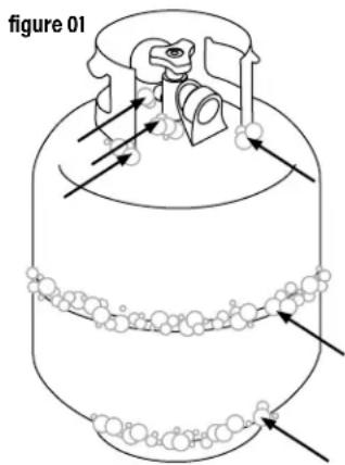
STEP 01 Use a clean paintbrush to brush a 10/90 mild soap and water solution onto joint areas of the LPG cylinder.
(Indicated by arrows in figure 01.)
- Leaks are indicated by growing bubbles.
WARNING
If growing bubbles appear during leak test, DO NOT use or move the LPG cylinder. Immediately contact an LPG supplier or fire department.
text_image
figure 01FITTINGS & HOSES
- Annual checking and tightening of metal fittings is recommended.
- Keep the fuel supply hose away from any heated surfaces.
- Before each use, check to see if hoses are cut or worn.
- Replace damaged hose before using appliance.
(Use only Blackstone approved valve, hose, or regulator. Failure to comply will void the warranty.)
REGULATOR SAFETY
- Use this appliance, as purchased, only with gas and regulator/valve assembly supplied.
- DO NOT cross thread the connection between your LPG cylinder and regulator.
Cross threading can occur if you force thread a connection at an improper angle. This will damage the threads, lead to propane leaking, and potentially result in a build-up of fuel that can ignite.
- If you can not connect the regulator, DO NOT use the regulator.
Regulator must be replaced with a Blackstone approved model by a professionally licensed, authorized dealer.
CONNECT THE LPG CYLINDER
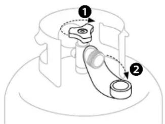
STEP 01 Turn the control knobs to OFF.
① Ensure that the LPG cylinder is OFF by turning the OPD hand wheel clockwise to a full stop.
② Remove the safety cap from the Type 1 valve outlet.
text_image
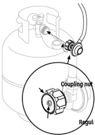
Diagram of a mechanical device with labeled parts and directional arrows indicating motion or forceSTEP 02 Hold the regulator in a straight line with the Type 1 valve outlet so as not to cross thread the connection.
Center and insert the regulator nipple into the Type 1 valve outlet.
Hand-tighten the coupling nut in a clockwise direction. (DO NOT use tools to connect.) If connection cannot be completed, disconnect regulator and repeat this step.
text_image
Coupling nut Regul:The safety relief valve must face away from the user while the appliance is in use.
LEAK TEST: VALVES, HOSE & REGULATOR
STEP 01 Turn the control knobs to OFF.
STEP 02 Connect the regulator to the LPG cylinder.
STEP 03 Completely open the LPG tank by turning the OPD hand wheel counterclockwise.
- If you hear a rushing sound, turn gas off immediately. There is a major leak at the connection.
- Immediately close the LPG cylinder by turning the OPD hand wheel clockwise and re-tighten connections. If leaks cannot be stopped DO NOT TRY TO REPAIR.
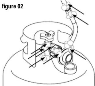
STEP 04 Use a clean paintbrush to brush a 10/90 mild soap and water solution onto joint areas of valves and regulator. (Indicated by arrows in figure 02.)
- Leaks are indicated by growing bubbles.
- Immediately close the LPG cylinder by turning the OPD hand wheel clockwise and re-tighten connections.
text_image
figure 02WARNING
If leaks cannot be stopped, DO NOT try to repair. Regulator must be replaced with a Blackstone approved model by a professionally licensed, authorized dealer.
DISCONNECTING THE LPG CYLINDER
20 LB (9 KG)
STEP 01 Ensure that the control knobs are turned to OFF.
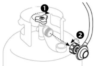
① Ensure that the LPG cylinder is OFF by turning the OPD hand wheel clockwise to a full stop.
② Turn the coupling nut counter-clockwise by hand to remove the regulator. (DO NOT use tools to disconnect.)
text_image
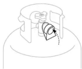
Technical diagram showing mechanical assembly with numbered components and dashed alignment lineSTEP 02 Place dust cap on LPG cylinder valve outlet whenever cylinder is not in use.
Only install the type of dust cap on cylinder valve outlet that is provided with the cylinder valve. Other types of caps or plugs may result in leakage of propane.
natural_image
Pure mechanical diagram showing a gear or cam mechanism inside a cylindrical housing (no text or symbols)IGNITION INSTRUCTIONS
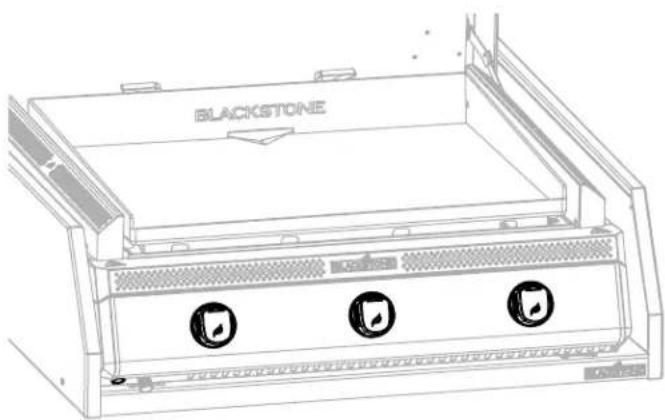
1. CHECK VALVES
STEP 01 Turn knob to OFF position.
STEP 02 Push in knob and release. Knob should spring back. If knobs DO NOT spring back, replace valve assembly before using appliance.
STEP 03 Rotate knob to LOW then turn back to OFF. Knob should turn smoothly.

WARNING
If burner does not ignite with open LPG cylinder valve, gas will continue to flow out of burner and could accidentally/ inadvertently ignite with risk of injury. Ensure gas is off at the supply shut off valve before checking appliance valves.
text_image
BLACKSTONE2. ELECTRIC IGNITION
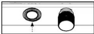
⚠ DO NOT lean over the appliance while lighting. Make sure the appliance is plugged in.
STEP 01 Press the ON button. (Optional: Turn the dimmer until it clicks to turn off the puddle lights.)
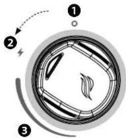
STEP 02
① Push the control knob in to start gas flowing. (WHITE)
② Turn the control knob counter-clockwise to activate the starter. (FLASHING BLUE)
③ Adjust the temperature to desired level. (ORANGE)
text_image
Diagram of a mechanical or electrical component with numbered parts and directional arrows indicating motion or force.Note: If the magnet in the knob is disconnected, the indicator light will be orange. If the knob arrow is facing UP, gas is not flowing.
3. CHECK BURNER FLAME
Always check burner flame before use.
STEP 01 Light burners and rotate knobs from HIGH to LOW.
STEP 02 Look below the cooking top to view burners. When knob is at HIGH, flames should be larger than when knob is at LOW.
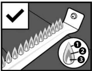
HEALTHY BURNER FLAME PATTERN
text_image
Diagram showing a fire-resistant tool with flame-like patterns and a numbered inset highlighting three key points.① Flickers of yellow color.
② Dark blue color.
③ Vibrant blue.
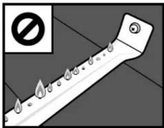
BURNER FLAMES ARE YELLOW OR IRREGULAR
text_image
Safety warning symbol with a pipe and flame icons, indicating no protection or hazardIf there is a sudden drop or low flame issue, please reference the Troubleshooting chapter.
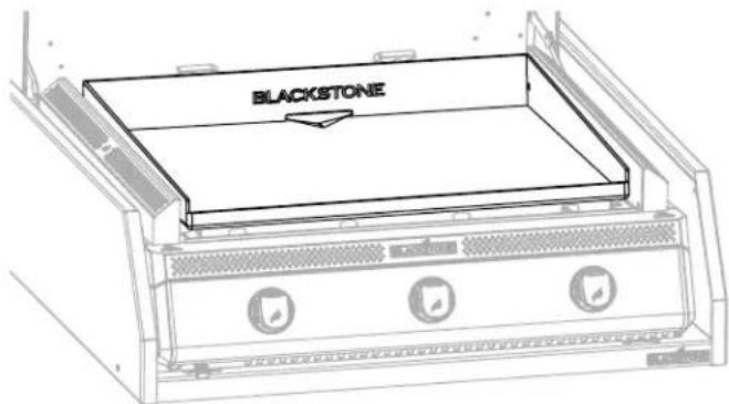
GRIDDLE SEASONING INSTRUCTIONS
text_image
BLACKSTONEWASHING YOUR GRIDDLE TOP BEFORE FIRST USE
NOTICE
Soap will ruin a seasoned griddle. This is the only time you should use soap on the griddle cooking surface.
STEP 01 Wash the griddle cooking surface with hot, soapy water.
STEP 02 Rinse and dry completely.

VIDEO TUTORIAL
How to Season a New Blackstone Griddle
youtube.com/watch?v=VspmDVnj2pl&t=3s
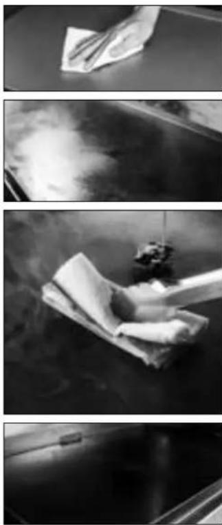
STEP 01 Wipe any debris off griddle top.
STEP 02 Set your griddle to high heat until your griddle top changes color. (\~10 min)
STEP 03 Use tongs to hold a paper towel or cotton cloth and spread 2-3 tablespoons of your seasoning oil across the entire griddle top. When seasoning your griddle top, remember to use a thin and even layer of oil—the thinner the layer of oil, the easier it will be to burn it off.
STEP 04 The griddle top is ready for another layer of oil when it stops smoking. Repeat STEP 03 3-4 times, or until the griddle surface is black.
WHAT OIL IS BEST TO USE?
- Blackstone Seasoning and Cast Iron Conditioner.
- Any plant-based cooking oil.
- Rendered animal fat with no additives.

text_image
BLACKSTONE GRIDDLE SEASONING CACT IRON CONDITIONERSEASONING TROUBLESHOOTING
THERE IS A BROWNISH RESIDUE ON THE GRIDDLE SURFACE:
POSSIBLE CAUSES SOLUTION
- Too much oil was used.
- You turned off the heat too soon.
STEP 01 Turn your griddle on high and let it heat for 10-15 minutes.
STEP 02 Scrape off as much of the thickened and partially cooked oil as you can.
STEP 03 Re-season with a very thin layer of oil.
THE EDGES OF THE GRIDDLE SURFACE ARE NOT BLACK:
After using your griddle for multiple cooks, the seasoning will even out and improve.
PREVENTING RUST
Use your griddle frequently. Every time you cook, you are adding to the seasoning, which makes rust less likely.
NOTICE
If you live in a humid or coastal climate, your griddle may require more frequent seasonings between uses.
If rust appears on the griddle surface, rub it off with steel wool, low grit sandpaper or the Blackstone Pumice Stone and re-season the surface.

VIDEO TUTORIAL
Recovering your Blackstone Griddle Top
youtube.com/watch?v=thPE2IgnSil
COOKING ON YOUR BLACKSTONE
CAUTION
This appliance will be hot during and after use. Use long-handled utensils and oven mitts/ protective gloves when handling potentially hot parts to protect against burns and splatters.
NOTICE
DO NOT store any items within 3 in (8 cm) of the cooking surface while in use.
IF GREASE OR OTHER HOT MATERIAL DRIPS ONTO VALVE, HOSE OR REGULATOR:
STEP 01 Turn off gas supply immediately.
STEP 02 Determine the cause and correct it.
STEP 03 Clean and inspect valve, hose and regulator.
STEP 04 Perform a leak test. (Please reference the Leak Test Instructions)
VIDEO RECIPES
Find recipes and cooking tips at:
BlackstoneProducts.com/blogs/recipes
youtube.com/c/BlackstoneGriddles
@blackstoneproducts

text_image
STRAWBERRIES AND CREAM PANCAKES Breakfast OKLAHOMA FRIED ONION BURGER Lunch TACOS BORRACHOS DinnerCLEANING YOUR GRIDDLE TOP
Clean griddle top after each use, while still warm.
- DO NOT use soap on the griddle top. This will destroy the griddle's seasoning.
- The grease cup must be removed and emptied after each use.
CAUTION
Grease cup will be hot during and after use. DO NOT remove the grease cup until the griddle has completely cooled.

VIDEO TUTORIAL
How to Clean your Blackstone Griddle
youtube.com/watch?v=-ledu9z6NPY
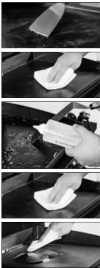
STEP 01 Push loose food debris into the grease cup with spatula or straight metal scraper.
STEP 02 Wipe down griddle top with paper towel.
STEP 03 Apply a few tablespoons of water to the griddle surface, then scrape the water and debris into the grease cup.
(For stuck-on food residue, use a bit of coarse salt.)
STEP 04 Wipe again with a paper towel and dry completely.
STEP 05 Apply thin coat of cooking oil to maintain seasoning and protect the griddle top.
natural_image
Four-panel black-and-white photo sequence showing hand cleaning a surface with a spray can, no text or symbols visibleCLEANING YOUR APPLIANCE
WARNING
Grease build up can cause a fire. Clean any part of the appliance that gets hot and experiences grease build up after each use.
CAUTION
All cleaning and maintenance should be carried out when the appliance is cool and with the fuel supply turned OFF at the LPG cylinder.
- DO NOT use abrasive pad on areas with graphics.
- If a bristle brush is used to clean any of the cooking surfaces, ensure no loose bristles remain on cooking surfaces prior to cooking.
PLASTIC PARTS & PAINTED SURFACES:
Wash with warm soapy water and wipe dry with a non-abrasive cloth.
NOTICE
DO NOT use Citrisol, abrasive cleaners, or a concentrated cleaner on plastic parts. This may result in damage to and failure of parts.
APPLIANCE STORAGE
WARNING
DO NOT move the appliance when in use. Allow the appliance to cool to 115°F (45°C) before moving or storing.
Storage of an appliance indoors is only permissible if the gas supply is disconnected and removed from the appliance.
COVER FIT GUIDE
Always cover your appliance when stored outdoors.

To find a cover that will fit your appliance, visit BlackstoneProducts.com/support.
CLEANING THE BURNER ASSEMBLY
To reduce chance of "flash-back" the procedure below should be followed at least once a month when spiders are most active or when your appliance has not been used for a period of time.

VIDEO TUTORIAL
How to Clean Your Burner Tube
youtube.com/watch?v=xKQTCrFCzf8
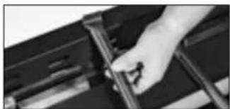
STEP 01 Ensure that the gas is turned OFF at control knobs and gas supply. Remove the griddle top.
STEP 02 Carefully detach and remove the burner.
STEP 03 Clean the inside of the burner:
- Run a narrow bottle brush through each burner tube several times. (DO NOT use wire brushes)
- Run a stiff wire bent into a small hook through each burner tube several times.
- Use compressed air to blow through the burner tube and out the burner ports. Check that air blows through each hole. (Wear eye protection)
STEP 04 Brush entire outer surface of burner to remove grime.
STEP 05 Clean any blocked ports with stiff wire such as an open paper clip.
STEP 06 Carefully replace burners and reattach, with attention to the location of the ignition needle.
natural_image
Close-up of a hand holding a mechanical component (no visible text or symbols)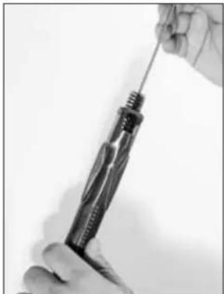
natural_image
Close-up of hands using a screwdriver to adjust a screwdriver (no text or symbols visible)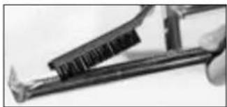
natural_image
Close-up of a hand using a tool to cut or wire a metal component (no visible text or symbols)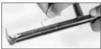
natural_image
Close-up of a hand using a tool to draw or apply material, no visible text or symbols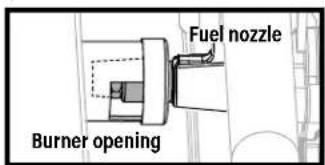
text_image
Fuel nozzle Burner openingThe gas rail fuel nozzle must be reengaged within the burner opening.
TROUBLESHOOTING
IGNITION TROUBLESHOOTING
BURNER WILL NOT IGNITE:
If ignition does not occur in 5 seconds:
STEP 01 Turn the burner control knob OFF.
STEP 02 Wait 5 minutes.
STEP 03 Repeat the lighting procedure.
If this does not work, to determine the cause, please try to ignite your appliance with a match.
MATCH LIGHTING INSTRUCTIONS
Before beginning, check for gas leaks. Open hood (if applicable).
STEP 01 Turn control knob to OFF position.
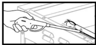
STEP 02 Light a match (or long lighter) no shorter than 11 inches long.
STEP 03 Place the flame next to the burner.
natural_image
Illustration of a hand holding a tool next to a window with a small object nearby (no text or symbols)STEP 04 Push in and turn the control knob to start gas flowing. Ensure burner lights and stays lit.
IF YOU CAN IGNITE YOUR APPLIANCE WITH A MATCH:
POSSIBLE CAUSES SOLUTION
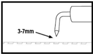
| Ignitor wire misaligned. | Ensure that the ignition needle is positioned 3-7mm away from the burner tube, and above a burner hole. |
 |
Damage to the ignition system.
Contact customer support for replacement parts.
IF YOU CAN NOT IGNITE YOUR APPLIANCE WITH A MATCH:
POSSIBLE CAUSES SOLUTION
| Burner tubes are not receiving fuel. | Clean the burner assembly to remove the obstruction. |
GAS FLOW TROUBLESHOOTING
BURNER FLAMES ARE YELLOW OR IRREGULAR:
- Appliance will not achieve a high heat or heats unevenly.
- Burner flames start strong, then immediately drop to low even when burner is set to high position.
- Flame height drops when a second burner is lit.
- Flames DO NOT extend the full length of the burner, or only run on one side of the burner.
- Burner flames are inconsistent.
POSSIBLE CAUSES SOLUTION
| Obstructions in the burner, gas jets, or fuel rail. | Clean the burner, jets, and gas hose. |
| LPG cylinder is empty or low. | Refill or replace the LPG cylinder. |
| The regulator's flow limiting device was triggered. | Reset the safety system:STEP 01Turn OFF the appliance, close the LPG cylinder valve, and disconnect the regulator from the LPG cylinder.STEP 02Wait five minutes to allow the pressure to dissipate, then reconnect the regulator to the LPG cylinder and slowly open the OPD hand wheel one half turn.STEP 03Ignite your appliance. |
| Regulator stuck in safety position. | Contact customer support for replacement parts. |
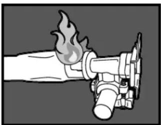
A FLAME IS COMING OUT OF THE AIR GATE:
natural_image
Illustration of a fire extinguisher with flame and smoke (no text or symbols)POSSIBLE CAUSES SOLUTION
| Something is blocking the venturi in the burner. | Clean the burner assembly to remove the obstruction. |
REPLACING THE CONTROL KNOB'S PRINTED CIRCUIT BOARD
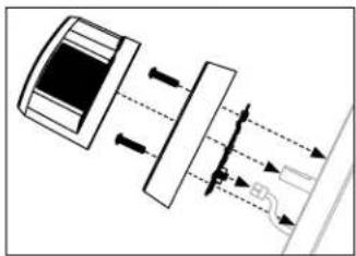
If the control knob does not work, the PCB may need to be replaced.
STEP 01 Pull out the non-functional control knob and set aside.
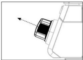
natural_image
Technical line drawing of a mechanical component with an arrow indicating direction (no text or symbols)STEP 02 Use a Philips head screwdriver to remove the two (2) M4x10 screws from the knob bezel and set aside.
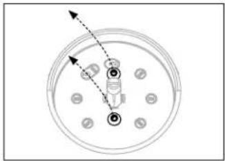
natural_image
Top-down diagram of a circular mechanical or electrical component with numbered pins and arrows indicating direction (no text or symbols)STEP 03 Remove the knob bezel and set aside.
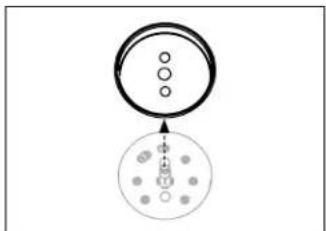
natural_image
Simple diagram showing a circle with three dots and an arrow pointing to a dotted pattern inside a larger circle (no text or symbols)STEP 04 Lift out the knob PCB, and disconnect the wire from the back of the knob PCB.
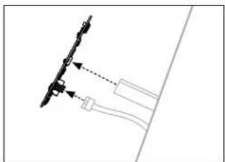
natural_image
Pure technical diagram showing a mechanical assembly with arrows indicating direction (no text or symbols)STEP 05 Plug the connector into the new knob PCB. Reverse the above assembly steps to reinstall the control knob.
natural_image
Diagram of a vehicle's internal components and airflow path (no text or labels)CUSTOMER SUPPORT
Visit us online at BlackstoneProducts.com/support for assistance concerning appliance use, replacement parts, or your warranty.
CUSTOMER SUPPORT HOURS:

Monday - Friday 7:00 am - 5:00 pm (Mountain Time)
BLACKSTONE®
This product may be covered by one or more issued U.S. and/or international patents and may include patent applications pending. For more information, please visit: BlackstoneProducts.com/patents
DISTRIBUTED BY NORTH ATLANTIC IMPORTS, LLC 1073 W 1700 N LOGAN, UT 84321 USA | BLACKSTONE IS A REGISTERED TRADEMARK OF NORTH ATLANTIC IMPORTS, LLC
MODÈLE: 6029 v07
natural_image
Technical line drawing of a server rack with three circular ports and a hanging control unit (no text or symbols)MANUEL DU PROPRIÉTAIRE
PLAQUE CHAUFFANTE XL DE 28 PO DROP-IN AVEC CAPUCHE ET VESTE ISOLANTE
TABLE DES MATIÈRES
INFORMATIONS DE SÉCURITÉ IMPORTANTES ....02
ACTIVEZ VOTRE GARANTIE....03
GUIDE D'ASSEMBLAGE....04
UTILISATION DE VOTRE BLACKSTONE 11
DÉPANNAGE....18
IMPORTANT:
BlackstoneProducts.com/support
CLÉ D'ALERTE DE SÉCURITÉ
! DANGER
natural_image
Three identical bolted components with threaded shafts, shown in isometric view (no text or symbols)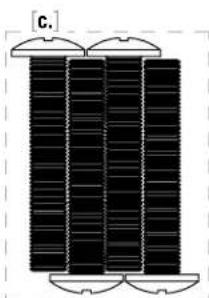
natural_image
Three vertical black bars with rounded tops, arranged horizontally (no text or symbols)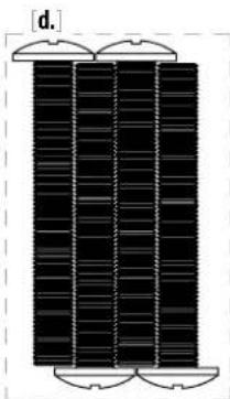
natural_image
Pure diagram of a vertical structure with three horizontal panels, no text or symbols present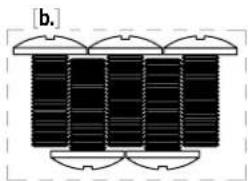
natural_image
Pure diagram of four vertical black bars with rounded ends, no text or symbols presentINSTRUCTIONS DE MONTAGE
natural_image
Line drawing of a cylindrical mechanical component with a central protruding element (no text or symbols)
NON INCLUS:
Bouteille GPL
Taille: 45 x 30 cm (18 x 12 po), 9 kg (20 lb)
natural_image
Line drawing of an open mechanical device with mounting holes and a handle, no text or symbols presentnatural_image
Technical line drawing of an open mechanical device with internal components and a handle (no text or symbols)text_image
Technical diagram of a refrigerator with labeled gauges and buttons, showing front panel and side view with icons.natural_image
Pure technical diagram showing a mechanical component with no text, numbers, or symbols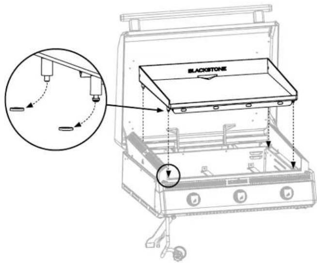
text_image
BLACKSTONEOPTION A : INSTALLER EN TANT QUE DROP-IN AVEC UNE VESTE ISOLANTE
natural_image
Technical line drawing of a rectangular frame with an inset magnified detail showing a corner detail (no text or symbols)natural_image
Technical line drawing of a rectangular frame with an inset close-up showing a detail (no text or symbols)natural_image
Technical line drawing of a structural component with an inset magnified detail (no text or symbols)natural_image
Technical line drawing of a rectangular electronic device with mounting holes and a side view showing internal components (no text or symbols)natural_image
Technical line drawing of a rectangular plate with mounting holes and two side supports, no text or symbols presentnatural_image
Technical drawing of a metal bracket with mounting holes and a side view showing internal components (no text or symbols)natural_image
Technical line drawing of a rectangular enclosure with a central cylindrical component and two vertical supports (no text or symbols)natural_image
Technical line drawing of a portable stove or appliance with control knobs and a base panel (no text or symbols)text_image
Technical diagram showing assembly steps of an electronic device with labeled components and exploded viewsnatural_image
Technical line drawing of a server rack with attached components and a magnified inset showing a hanging chain (no text or symbols)natural_image
Line drawing of a black stone oven with three buttons and ventilation slots (no text or symbols)natural_image
Technical line drawing of a device rear panel with cable routing and a magnified inset showing a cylindrical component (no text or symbols)natural_image
Line drawing of a portable stove mounted on a cabinet, with hoses and control valves (no text or symbols)text_image
A A A A A SANS VESTE A: 36 in (1 m)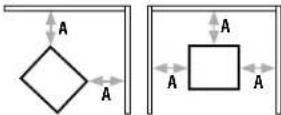
AVEC VESTE
A: 6 in (150 mm)
! AVERTISSEMENT
natural_image
Pure geometric line drawing of a 3D cube and a right-angle bracket (no text or symbols)natural_image
Two geometric line drawings: a triangular prism with internal lines and a square grid with intersecting lines (no text or symbols)text_image
figure 01RACCORDS ET TUYAUX
text_image
Diagram of a mechanical device with numbered components and directional arrows indicating motion or flow.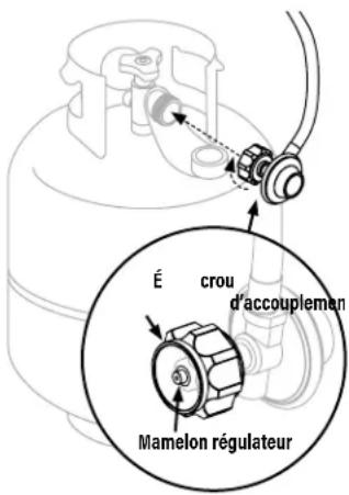
natural_image
Isometric line drawing of a rectangular device with labeled points A, B, and C (no text or symbols beyond labels)TEST DE FUITE: VANNES, TUYAU ET RÉGULATEUR
text_image
figure 02AVERTISSEMENT
text_image
Diagram showing mechanical assembly with labeled parts and directional arrows indicating motion or forcenatural_image
Pure mechanical diagram showing a gear or cam mechanism inside a cylindrical housing (no text or symbols)INSTRUCTIONS D'ALLUMAGE
1. CLAPETS ANTI-RETOUR
ÉTAPE 01 Tourner le bouton en position OFF.
text_image
BLACKSTONE2. ALLUMAGE ÉLECTRIQUE
natural_image
Two mechanical components with arrows indicating direction, no text or symbols present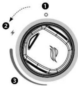
text_image
Diagram of a mechanical or electrical component with numbered parts and directional arrows indicating motion or force.text_image
Diagram showing a fire-resistant tool with flame-like patterns and a droplet labeled with three numbered parts.text_image
Safety warning symbol with flame icons and a prohibition sign, indicating no protection or hazard.text_image
BLACKSTONELAVER LE DESSUS DE VOTRE PLANCHA AVANT LA PREMIÈRE UTILISATION
AVIS
youtube.com/watch?v=VspmDVnj2pl&t=3s
natural_image
Grayscale abstract image with indistinct dark smudges and light streaks, no visible text or symbols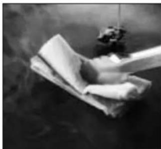
natural_image
Black-and-white photo of a cloth or paper piece being washed with a dark object, emitting smoke (no visible text or symbols)
natural_image
Close-up of a dark, reflective surface with a small rectangular object on top (no text or symbols visible)QUELLE HUILE EST PRÉFÉRABLE D'UTILISER?
CAUSES POSSIBLES LA SOLUTION
natural_image
Close-up of a hand inserting a small object into a device (no visible text or symbols)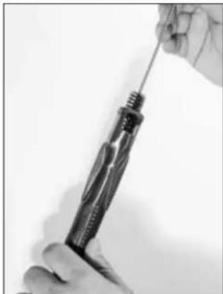
natural_image
Close-up of a hand using a screwdriver to adjust a screwdriver (no text or symbols visible)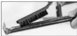
natural_image
Close-up of a hand using a tool to apply material, no visible text or symbols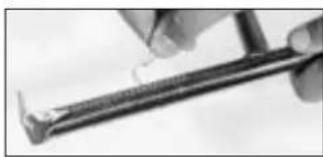
natural_image
Close-up of a hand holding a metal tool, no visible text or symbols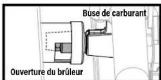
LLE BRÛLEUR NE S'ALLUME PAS:
INSTRUCTIONS D'ALLUMAGE DES ALLUMETTES
natural_image
Line drawing of a hand holding a tool near a window frame (no text or symbols)CAUSES POSSIBLES LA SOLUTION
CAUSES POSSIBLES LA SOLUTION
CAUSES POSSIBLES LA SOLUTION
natural_image
Illustration of a fire extinguisher with flame and smoke (no text or symbols)CAUSES POSSIBLES LA SOLUTION
natural_image
Diagram of a vehicle's side profile with a dashed arrow indicating direction (no text or symbols)natural_image
Top-down diagram of a circular mechanical or electrical component with numbered pins and arrows indicating direction (no text or symbols)chemical
Simple molecular structure diagram showing a ring with three oxygen atoms and a central atom bonded to two groups, enclosed in a larger circle with labeled atoms.natural_image
Pure diagram of a mechanical linkage or assembly without any text, numbers, or symbolsnatural_image
Diagram of a vehicle's internal components and airflow path (no text or labels)SERVICE CLIENTS
natural_image
Technical line drawing of a server rack with three circular ports and a hanging control unit (no text or symbols)MANUAL DEL PROPIETARIO
USANDO SU BLACKSTONE....11
BlackstoneProducts.com/register
natural_image
Three identical bolted components arranged in a row, each with different threaded shafts and mounting flanges (no text or symbols visible)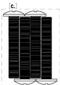
natural_image
Pure diagram of three vertical rectangular blocks with rounded corners, no text or symbols present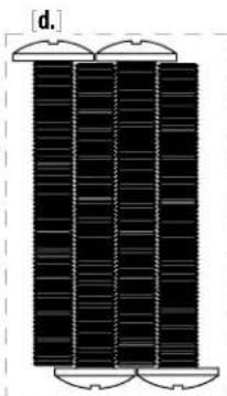
natural_image
Diagram of a vertical structure with three horizontal panels, each containing layered patterns and curved ends (no text or symbols)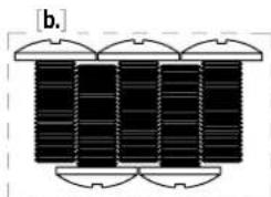
natural_image
Pure diagram of four vertical columns with rounded tops, no text or symbols presentINSTRUCCIONES DE MONTAJE
natural_image
Line drawing of a cylindrical mechanical component with a central hub and two side connectors (no text or symbols)
NO INCLUIDO:
natural_image
Technical line drawing of a mechanical device with open lid and internal compartments (no text or symbols)natural_image
Technical line drawing of an open mechanical device with internal components and a handle (no text or symbols)text_image
Technical diagram of a refrigerator with labeled gauges and buttons, showing internal structure and mounting points.natural_image
Pure technical diagram showing a mechanical component with alignment lines and arrows, no text or symbols present.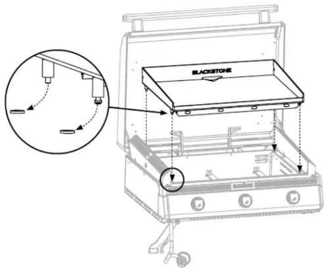
text_image
BLACKSTONEnatural_image
Technical line drawing of a mechanical component with an inset magnified detail (no text or symbols)natural_image
Technical line drawing of a rectangular frame with an inset close-up showing a detail (no text or symbols)natural_image
Technical line drawing of a mechanical component with an inset close-up showing a corner detail (no text or symbols)natural_image
Technical line drawing of a rectangular electronic device with mounting holes and a side view showing internal components (no text or symbols)natural_image
Technical line drawing of a rectangular frame with two vertical supports and mounting holes, no text or symbols present.natural_image
Technical drawing of a metal bracket with mounting holes and a side view showing internal components (no text or symbols)natural_image
Technical line drawing of a rectangular enclosure with a central cylindrical component and two vertical supports (no text or symbols)natural_image
Technical line drawing of a portable appliance with control panel and mounting bracket (no text or symbols)text_image
Technical diagram showing assembly of a device with three labeled parts: connector, cable connector, and cable connector assembly.natural_image
Technical line drawing of a mechanical device with a magnified inset showing a close-up of a component (no text or symbols present)PASO 11 Continúe con USANDO SU BLACKSTONE.
natural_image
Line drawing of a blackstone appliance with three buttons and ventilation slots (no text or symbols)natural_image
Technical line drawing of a computer monitor with cable connectors and ventilation slots, shown with an inset magnified view (no text or symbols)natural_image
Line drawing of a mounted appliance with three fans and a vertical tube, placed on a cabinet (no text or symbols)AVISO
USANDO SU BLACKSTONE
ANTES DE COCINAR
COMPROBAR QUEMADORES
natural_image
Pure geometric line drawing of a 3D cube and a right-angle bracket (no text or symbols)natural_image
Two geometric line drawings: a triangular prism with internal lines and a square grid with intersecting lines (no text or symbols)text_image
Diagram of a mechanical device with labeled parts and directional arrows indicating motion or force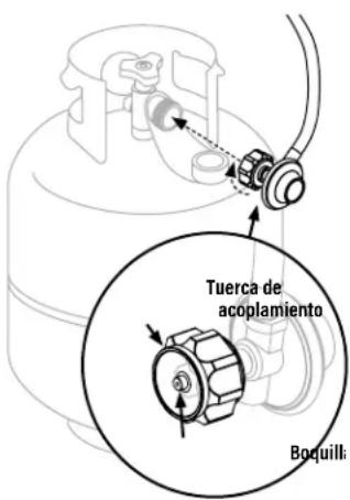
text_image
Tuerca de acoplamiento Boquillanatural_image
Isometric line drawing of a rectangular device with labeled points A, B, C and internal ventilation slots (no text or symbols beyond labels)text_image
Diagram of a mechanical device with labeled parts and motion arrows indicating movement or force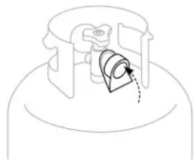
natural_image
Pure mechanical component diagram without any text, numbers, or symbolstext_image
ESPAÑOL BLACKSTONE2. ENCENDIDO ELÉCTRICO
natural_image
Simple diagram showing a ring and a cylindrical object with an arrow pointing upward (no text or symbols)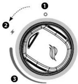
text_image
Diagram of a mechanical or electrical component with numbered parts and directional arrows indicating motion or force.text_image
Diagram showing a fire-resistant tool with flame-like patterns and a numbered inset highlighting three labeled parts.text_image
Safety warning symbol with flame icons and a prohibition sign, indicating no protection or hazard.text_image
BLACKSTONEyoutube.com/watch?v=VspmDVnj2pl&t=3s
natural_image
Grayscale medical scan image showing internal tissue structures (no visible text or labels)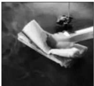
natural_image
Black-and-white photo of a cloth or paper piece being lifted by a smoke cover, with no visible text or symbols.
natural_image
Close-up of a dark, reflective surface with a small rectangular object on top (no text or symbols visible)COCINAR EN TU BLACKSTONE
ATENCIÓN
natural_image
Close-up of a hand holding a metal rod inserted into a black electronic device (no visible text or symbols)
natural_image
Close-up of a hand using a screwdriver to adjust a screwdriver (no text or symbols visible)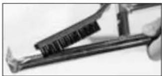
natural_image
Close-up of a hand using a power tool to draw or apply a metal component (no visible text or symbols)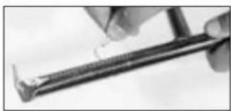
natural_image
Close-up of a hand using a tool to apply material or application (no visible text or symbols)