
ATTAX 80 - Audio Amplifier HUGHES & KETTNER - Free user manual and instructions
Find the device manual for free ATTAX 80 HUGHES & KETTNER in PDF.

User questions about ATTAX 80 HUGHES & KETTNER
0 question about this device. Answer the ones you know or ask your own.
Ask a new question about this device
Download the instructions for your Audio Amplifier in PDF format for free! Find your manual ATTAX 80 - HUGHES & KETTNER and take your electronic device back in hand. On this page are published all the documents necessary for the use of your device. ATTAX 80 by HUGHES & KETTNER.
USER MANUAL ATTAX 80 HUGHES & KETTNER
- Read all of these instructions!
- Save these instructions for later use!
- Follow all warnings and instructions marked on the product!
- Do not use this product near water, i.e. bathtub, sink, swimming pool, wet basement, etc.
- Do not place this product on an unstable cart, stand or table. The product may fall, causing serious damage to the product or to persons!
- Slots and openings in the cabinet and the back or bottom are provided for ventilation; to ensure reliable operation of the product and to protect it from overheating, these openings must not be blocked or covered. This product should not be placed in a built-in installation unless proper ventilation is provided.
- This product should not be placed near a source of heat such as a stove, radiator, or another heat producing amplifier.
- Use only the supplied power supply or power cord. If you are not sure of the type of power available, consult your dealer or local power company.
- Do not allow anything to rest on the power cord. Do not locate this product where persons will walk on the cord.
- Never break off the ground pin on the power supply cord.
- Power supply cords should always be handled carefully. Periodically check cords for cuts or sign of stress, especially at the plug and the point where the cord exits the unit.
- The power supply cord should be unplugged when the unit is to be unused for long periods of time.
- If this product is to be mounted in an equipment rack, rear support should be provided.
- This product should be used only with a cart or stand that is recommended by Hughes & Kettner.
- Never push objects of any kind into this product through cabinet slots as they may touch dangerous voltage points or short out parts that could result in risk of fire or electric shock. Never spill liquid of any kind on the product.
- Do not attempt to service this product yourself, as opening or removing covers may expose you to dangerous voltage points or other risks. Refer all servicing to qualified service personnel.
- Unplug this product from the wall outlet and refer servicing to qualified service personnel under the following conditions:
- When the power cord or plug is damaged or frayed.
- If liquid has been spilled into the product.
- If the product has been exposed to rain or water.
- If the product does not operate normally when the operating instructions are followed.
- If the product has been dropped or the cabinet has been damaged.
- If the product exhibits a distinct change in performance, indicating a need of service!
- Adjust only these controls that are covered by the operating instructions since improper adjustment of other controls may result in damage and will often require extensive work by a qualified technician to restore the product to normal operation.
- Exposure to extremely high noise levels may cause a permanent hearing loss.
- Individuals vary considerably in susceptibility to noise induced hearing loss, but nearly everyone will lose some hearing if exposed to sufficiently intense noise for a sufficient time. The U.S. Government's Occupational Safety and Health Administration (OSHA) has specified the following permissible noise level exposures:
| Duration Per Day In Hours | Sound LeveldBA, Slow Response |
| 8 | 90 |
| 6 | 92 |
| 4 | 95 |
| 3 | 97 |
| 2 | 100 |
| 1^1/_2 | 102 |
| 1 | 105 |
| /_3 | 110 |
^1/_4 or less 115
- According to OSHA, any exposure in excess of the above permissible limits could result in some hearing loss.
- Ear plug protectors in the ear canals or over the ears must be worn when operating this amplification system in order to prevent a permanent hearing loss if exposure is in excess of the limits as set forth above. To ensure against potentially dangerous exposure to high sound pressure levels, it is recommended that all persons exposed to equipment capable of producing high sound pressure levels such as this amplification system be protected by hearing protectors while this unit is in operation.
- Fuses: For continued protection against risk of fire, replace fuses only with the same type and ratings.
TO PREVENT THE RISK OF FIRE AND SHOCK HAZARD, DO NOT EXPOSE THIS APPLIANCE TO MOISTURE OR RAIN. DO NOT OPEN CASE; NO USER SERVICE-ABLE PARTS INSIDE. REFER SERVICING TO QUALIFIED SERVICE PERSONNEL.
PLEASE READ BEFORE USE AND KEEP FOR LATER USE!
- The unit has been built by Hughes & Kettner in accordance with IEC 6.5 and left the factory in safe working order. To maintain this condition and ensure non-risk operation, the user must follow the advice and warning comments found in the operating instructions. The unit conforms to Protection Class 1 (protectively earthed).
- HUGHES & KETTNER ONLY GUARANTEE THE SAFETY, RELIABILITY AND EFFICIENCY OF THE UNIT IF:
- Assembly, extension, re-adjustment, modifications or repairs are carried out by Hughes & Kettner or by persons authorized to do so.
- The electrical installation of the relevant area complies with the requirements of IEC (ANSI) specifications.
- The unit is used in accordance with the operating instructions.
- The unit is regularly checked and tested for electrical safety by a competent technician.
WARNING:
- If covers are opened or sections of casing are removed, except where this can be done manually, live parts can become exposed.
- If it is necessary to open the unit this must be isolated from all power sources. Please take this into account before carrying out adjustments, maintenance, repairs and before replacing parts.
- Adjustment, maintenance and repairs carried out when the unit has been opened and is still live may only be performed by specialist personnel who are authorized by the manufacturer (in accordance with VBG 4) and who are aware of the associated hazards.
- Loudspeaker outputs which have the IEC 417/5036 symbol (Diagram 1, below) can carry voltages which are hazardous if they are made contact with. Before the unit is switched on, the loudspeaker should therefore only be connected using the lead recommended by the manufacturer.
- Where possible, all plugs on connection cables must be screwed or locked onto the casing.
- Replace fuses using only those of the specified type and current rating.
- It is not permitted to use repaired fuses or to short-circuit the fuse holder.
- Never interrupt the protective conductor connection.
- Surfaces which are equipped with the „HOT" mark (Diagram 2, below), rear panels or covers with cooling slits, cooling bodies and their covers, as well as tubes and their covers are purposely designed to dissipate high temperatures and should therefore not be touched.
- High loudspeaker levels can cause permanent hearing damage. You should therefore avoid the direct vicinity of loudspeakers operating at high levels. Wear hearing protection if continuously exposed to high levels.
MAINS CONNECTION:
- The unit is designed for continuous operation.
- The set operating voltage must match the local mains supply voltage.
- Caution: The unit mains switch must be in position '0' before the mains cable is connected.
- The unit is connected to the mains via the supplied power unit or power cable.
- Power unit: Never use a damaged connection lead. Any damage must be rectified by a competent technician.
- Avoid connection to the mains supply in distributor boxes together with several other power consumers.
- The plug socket for the power supply must be positioned near the unit and must be easily accessible.
PLACE OF INSTALLATION:
- The unit should stand only on a clean, horizontal working surface.
- The unit must not be exposed to vibrations during operation.
- Keep away from moisture and dust where possible.
- Do not place the unit near water, baths, wash basins, kitchen sinks, wet areas, swimming pools or damp rooms. Do not place objects containing liquid on the unit - vases, glasses, bottles etc.
- Ensure that the unit is well ventilated.
- Any ventilation openings must never be blocked or covered. The unit must be positioned at least 20 cm away from walls. The unit may only be fitted in a rack if adequate ventilation is ensured and if the manufacturer's installation instructions are followed.
- Keep away from direct sunlight and the immediate vicinity of heating elements and radiant heaters or similar devices.
- If the unit is suddenly moved from a cold to a warm location, condensation can form inside it. This must be taken into account particularly in the case of tube units. Before switching on, wait until the unit has reached room temperature.
- Accessories: Do not place the unit on an unsteady trolley, stand, tripod, base or table. If the unit falls down, it can cause personal injury and itself become damaged. Use the unit only with the trolley, rack stand, tripod or base recommended by the manufacturer or purchased together with the unit. When selling the unit up, all the manufacturer's instructions must be followed and the setup accessories recommended by the manufacturer must be used. Any combination of unit and stand must be moved carefully. A sudden stop, excessive use of force and uneven floors can cause the combination of unit and stand to tip over.
- Additional equipment: Never use additional equipment which has not been recommended by the manufacturer as this can cause accidents.
- To protect the unit during bad weather or when left unattended for prolonged periods, the mains plug should be disconnected. This prevents the unit being damaged by lightning and power surges in the AC mains supply.
CONSEILS DE SECURITE IMPORTANTS!
PRIERE DE LIRE AVANT L'EMPLOI ET A CONSERVER POUR UTILISATION ULTERIEURE!
Congratulations and thank you for choosing the Hughes & Kettner ATTAX 80 amp!
A team of guitarists and technicians developed the ATTAX amps with a single purpose in mind: To provide you with sophisticated guitar sounds and practical features in an easy-to-handle package.
The ATTAX 80 is the ideal workhorse for discerning players who want happening tone in a compact gig amp. The ATTAX 80's high-performance Current Feedback power amp not only delivers 100 watts of punch, but also the sought-after tone of a classic tube amp.
The ATTAX 80 has the sound, versatility and features to deliver the goods at professional gigs.
Its logical control layout gives you immediate access to the ATTAX 80's world of sound. This manual introduces you to its features and many application options.
We wish you a lot of fun and success with your new ATTAX 80!
TABLE OF CONTENTS
- Check that the local current and the amp's AC power rating are identical before you plug the power cord into an AC outlet.
- Ensure air can circulate around your amp's ventilation ducts.
- Make sure you place the amp on a stable platform where it is not exposed to mechanical shocks and temperature extremes which may damage the amp or endanger the safety of bystanders.
- Hughes & Kettner is not liable for damages due to improper use.
1.0 CHANNELS
The ATTAX 80 features a newly developed preamp that not only produces authentic harmonic overdrive but also a truly dynamic response to your picking style. Based on semiconductors, this innovative circuitry simulates the sound-shaping elements of tube amps and delivers sound quality unparalleled in this price range. It also provides the dynamics demanding guitarists require for musical expression.
CLEAN:
Depending on the preamp control settings, the ATTAX 80 delivers a variety of contemporary and vintage clean tones. At higher VOLUME settings, the "SoftClick" circuitry delivers that slight edge you would expect from a vintage tube amp. If desired, the CLEAN channel will put out plenty of crunch.
LEAD 1 + 2:
This channel delivers direct, in-your-face classic rock sounds with a very British feel. Switch to the LEAD 2 sound mode to get a completely different tonal character - even more bottom end, compression and sustain - in other words, the distinctive performance characteristics of modified tube amps, ideal for modern lead playing and heavy-duty power chord riffing.
REVERB:
The ACCUTRONICS ^® 3-spring reverb is renowned for its excellent sound quality and warm tone. In the signal chain, the ATTAX 80 reverb section is located after the FX loop so you can use it for external effects and still achieve a clean reverb sound. Additionally, the reverb level automatically adjusts its own level when you switch between channels, more for clean, less for lead.
2.0 JACKS AND CONTROL FEATURES
flowchart
graph TD
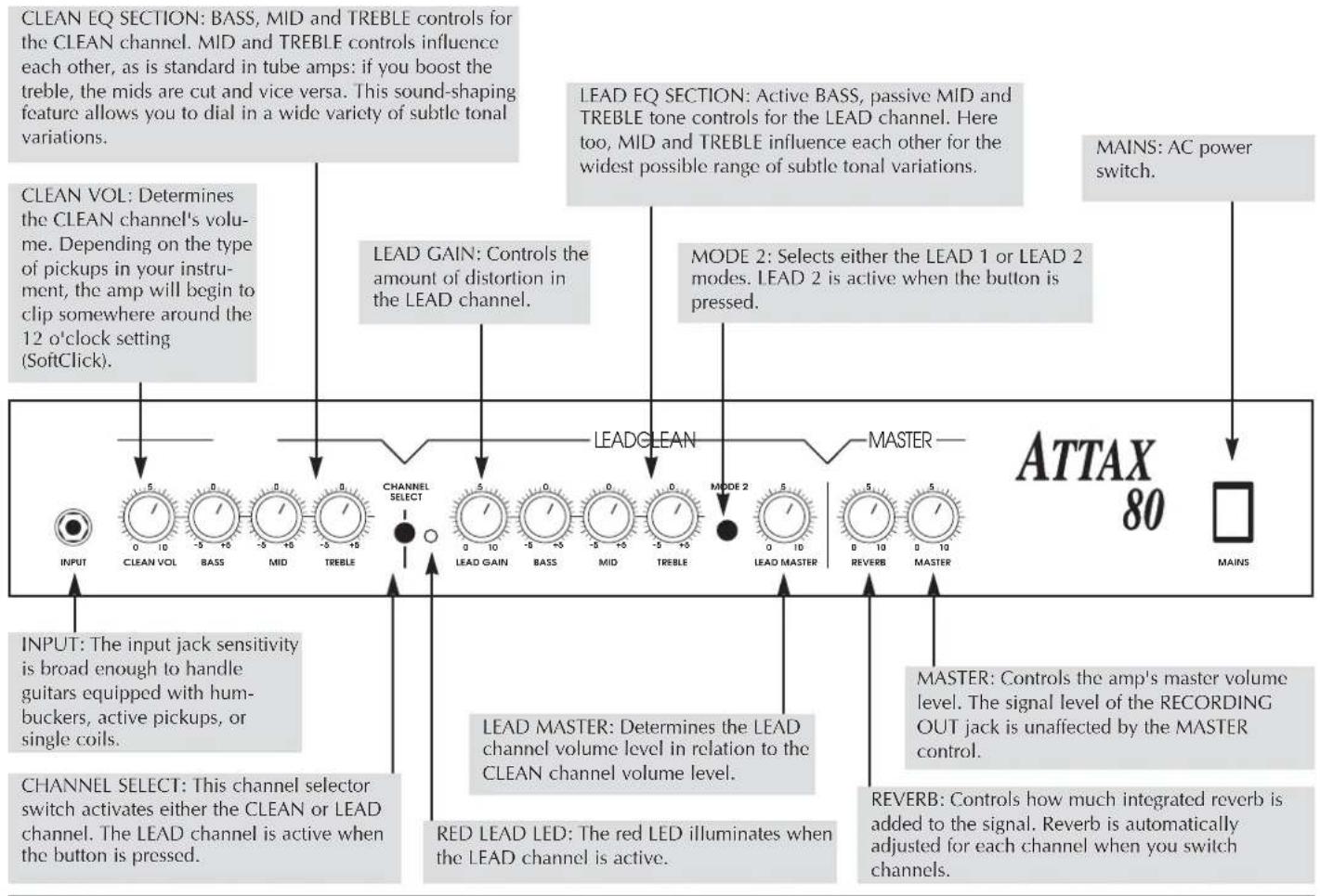
A["INPUT: The input jack sensitivity is broad enough to handle guitars equipped with hum-buckers, active pickups, or single coils."] --> B["CHANNEL SELECT: This channel selector switch activates either the CLEAN or LEAD channel. The LEAD channel is active when the button is pressed."]
C["CLEAN VOL: Determines the CLEAN channel's volume. Depending on the type of pickups in your instrument, the amp will begin to clip somewhere around the 12 o'clock setting (SoftClick)."] --> D["CHANNEL SELECT: This channel selector switch activates either the CLEAN or LEAD channel. The LEAD channel is active when the button is pressed."]
E["LEAD GAIN: Controls the amount of distortion in the LEAD channel."] --> F["LEAD GAIN"]
G["LEAD GAIN"] --> H["LEAD GAIN"]
I["MODE 2: Selects either the LEAD 1 or LEAD 2 modes. LEAD 2 is active when the button is pressed."] --> J["LEAD GAIN"]
K["MAINS: AC power switch."] --> L["MASTER"]
M["LEAD MASTER: Determines the LEAD channel volume level in relation to the CLEAN channel volume level."] --> N["RED LEAD LED: The red LED illuminates when the LEAD channel is active."]
O["REVERB: Controls how much integrated reverb is added to the signal. Reverb is automatically adjusted for each channel when you switch channels."] --> P["REVERB"]
Q["ATTAX 80"] --> R["MAINS"]
text_image
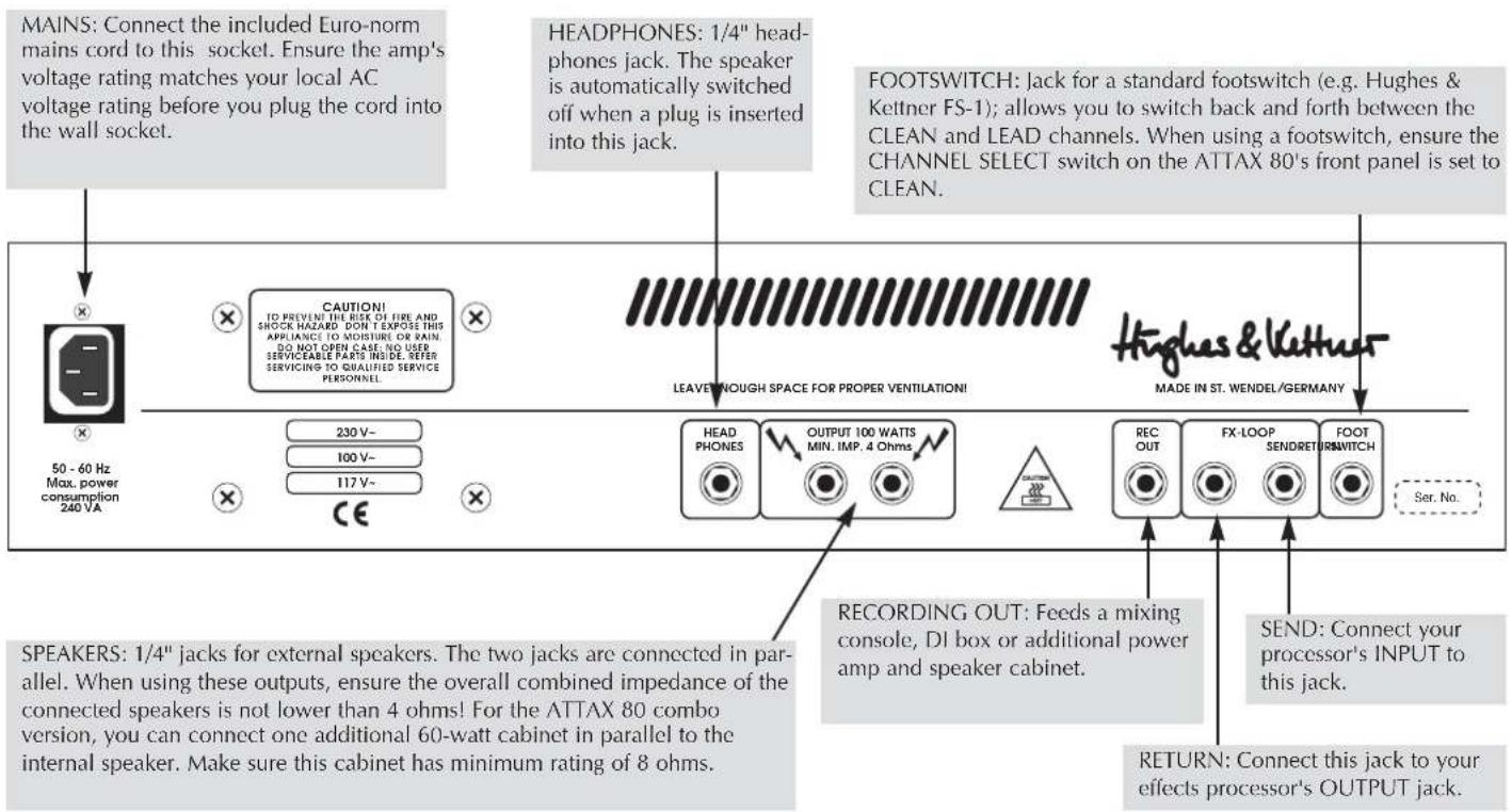
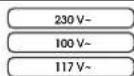
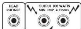
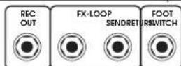
MAINS: Connect the included Euro-norm mains cord to this socket. Ensure the amp's voltage rating matches your local AC voltage rating before you plug the cord into the wall socket. HEADPHONES: 1/4" headphones jack. The speaker is automatically switched off when a plug is inserted into this jack. FOOTSWITCH: Jack for a standard footswitch (e.g. Hughes & Kettner FS-1); allows you to switch back and forth between the CLEAN and LEAD channels. When using a footswitch, ensure the CHANNEL SELECT switch on the ATTAX 80's front panel is set to CLEAN. LEAVE NOUGH SPACE FOR PROPER VENTILATION! MADES 50 - 60 Hz Max. power consumption 240 VA. CAUTIONI TO PREVENT THE RISK OF FIRE AND SHOCK HAZARD DON'T EXPOSE THIS APPLIANCE TO MOISTURE OR RAIN. DO NOT OPEN CARE. NO USER SERVICEABLE PARTS INSIDE, REFER SERVICING TO QUALIFIED SERVICE PERSONNEL. 230 V- 100 V- 117 V- RECORDING OUT: Feeds a mixing console, DI box or additional power amp and speaker cabinet. RECORDING OUT FX-LOOP SENDRET FOOT SWITCH SER. No. SPEAKERS: 1/4" jacks for external speakers. The two jacks are connected in parallel. When using these outputs, ensure the overall combined impedance of the connected speakers is not lower than 4 ohms! For the ATTAX 80 combo version, you can connect one additional 60-watt cabinet in parallel to the internal speaker. Make sure this cabinet has minimum rating of 8 ohms. RETURN: Connect this jack to your effects processor's OUTPUT JACK.3.0 STANDARD SETUP/ CABLE CONNECTIONS
flowchart
graph TD
    A["FOOTSWITCH FS-1"] --> B["INPUT"]
    B --> C["SPEAKER OUT"]
    C --> D["AC 112"]
    D --> E["FX-UNIT"]
    E --> F["OUT"]
    F --> G["RETURN"]
    G --> H["REC OUT"]
    H --> I["RED BOX"]
    I --> J["MIC IN"]
    J --> K["LINE IN"]
    K --> L["POWERAMP"]
    L --> M["GUITAR CABINET"]
    M --> N["PHONES"]
    N --> O["Speaker OUT"]
    O --> P["AC 112"]
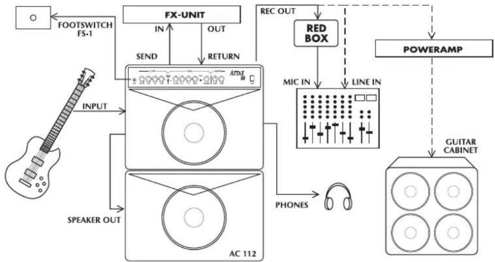
Use the CHANNEL SELECT switch or an external footswitch to change channels.
NOTE: Before using a footswitch, set the CHANNEL SELECT switch on the front panel of the amp itself to the CLEAN position.
Use the LEAD MODE switch to select either LEAD 1 or LEAD 2 mode.
4.2 THE ATTAX 80 AND SIGNAL PROCESSORS
The effects loop on the ATTAX 80 is a serial effects loop; the entire preamp signal is routed to the effects device and processed there.
Toconnect a signal processor:
- Connect the processor's INPUT to the ATTAX SEND jack and its OUTPUT to the ATTAX RETURN jack.
- To avoid noise, signal degradation, and intermittent signals, only use high-quality patch cables.
- Make sure the processor is not distorting the signal. Check the processor's gain LEDs (if it is equipped with this type of display) and use the input and output controls to dial in a suitable level.
- Distortion devices are not designed for use in an FX loop. As a rule of thumb, any kind of device that compresses the signal should be connected first in the signal chain.
Depending on the type of effect you want to achieve, you may want to connect your compressor directly between the instrument and the amp's input.
- If you are using several processors or stomp boxes, ensure you connect them in the proper order.
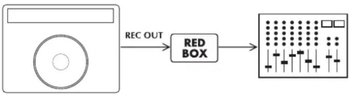
4.3 RECORDING OUTPUT
The ATTAX 80 is equipped with a recording output. This output features a filter, similar to the Hughes & Kettner RED BOX, that enhances the quality of the recording signal to such an extent that, for routine recording applications, you don't need to deal with the hassle of miking a cabinet.
However, for absolutely top-notch professional recording purposes, speaker simulation delivers an even more authentic signal. If you want to feed the ATTAX 80's signal to a mixing console in the studio or on stage, we recommend you route it through a Hughes & Kettner RED BOX. The RECORDING OUT signal path is designed so you can simply patch it directly into a RED BOX, which balances the signal and delivers sophisticated speaker simulation.
The following diagram illustrates how to connect the devices:
flowchart
graph LR
    A["Input"] -->|REC OUT| B["Red Box"]
    B --> C["Display Output"]
TIP: Try mixing the RECORDING OUT signal with the signal from the cabinet microphone. This is especially effective when the stage volume is fairly low or you are playing a quiet interlude. Generally, the sound will be better than if you use just the microphone signal. Another advantage is that the RECORDING OUT signal delivers a sufficient level for the mixing console even at low volume levels.
5.0 SERVICE AND PREVENTIVE MAINTENANCE
The ATTAX 80 does not require service of any type. However, there are a few precautions you should heed to ensure your amp lasts for many years.
- Ensure all peripheral devices, cords and cables are in a state of good repair. Defective speaker cables are the most common cause of power amp failure. Poor quality cables will cause hum and undesirable noise.
- Make certain your amp's ventilation ducts are not blocked or covered. Proper cooling will prolong the life of your amp.
- Avoid mechanical shocks and exposure to extreme heat, dust and especially moisture.
- When connecting peripheral devices, always pay close attention to their specifications. Never connect devices with high output signal levels (e.g. power amps) to your amp's input.
- Ensure you have the correct AC power rating available before you plug in the amp. If in doubt, ask the venue's sound technician or the custodian of the building you are rehearsing in.
- Refrain from do-it-yourself repairs! Have a qualified service technician replace internal fuses.
Use a soft damp cloth to clean the exterior surface of the ATTAX 80.
6.0 TROUBLESHOOTING
1) The ATTAX will not switch on:
- The amp is not getting any AC power. Check the mains cable to see if it is connected properly.
- The mains fuse is defective. Replace the fuse with another identical fuse. If this fuse also trips, consult your Hughes & Kettner dealer.
2) The ATTAX is connected properly, but no sound is audible.
- One or several GAIN and MASTER controls may be turned all the way down. Dial in a higher setting.
- A short circuit in the speaker signal chain may have tripped an internal fuse. Make sure none of the connections are shorted out and have a qualified service technician replace the fuse (identical specifications are a must).
3) The CLEAN channel will not activate via a footswitch:
- The front panel selector switch is in the LEAD position. Set it to CLEAN (in this case, CLEAN = off).
- The footswitch is not connected to the ATTAX. Plug it into the appropriate jack.
4) When accessed, the RECORDING OUT jack causes annoying hum.
- An electrical or magnetic field is causing interference. Use higher quality cables or re-arrange the cables you are using to reduce interference to a minimum. If this still doesn't improve the situation, use a DI box.
- The grounding of the connected devices may be causing a ground loop. DO NOT SEVER THE GROUND OF THE CONNECTED DEVICES UNDER ANY CIRCUMSTANCES! Try plugging all devices into the same socket via an AC power distributor/power strip. If this doesn't eliminate the noise, you must ensure the connection is galvanically separated by routing the signal through a DI box.
5) You have connected the RECORDING OUT jack to a mixing console and the signal is totally distorted, even when you have dialed in a clean sound.
- The RECORDING OUT signal may be overloading the mixing console's input. Reduce the mixing console's input sensitivity (GAIN). If this doesn't rectify the problem, patch the signal to the mixing console's LINE input.
6) You have connected the RECORDING OUT jack to a mixing console and the signal's volume level is way too low.
- The amp's output level is limited by an incorrectly adjusted FX processor's output level. Turn the FX processor's level up.
- The mixing console's line input is not sensitive enough. Turn up the gain. If this is still insufficient, use the microphone input (if necessary, use an adapter cable or DI box).
7) You have connected the RECORDING OUT jack to a mixing console, but you find it doesn't deliver the sound you had in mind.
The RECORDING OUT circuit is dual-purpose. It is also designed to allow you to feed its signal to an additional power amp and cabinet. For absolutely top-notch professional recording purposes, route the signal through a Hughes & Kettner REDBOX before patching it to a mixing console.
7.0 TECHNICAL DATA
PREAMP SECTION: CLEAN + LEAD solid state channels
INPUT: -10 dBV/ 1M ohms
FX-RETURN: -10dBV/ 47 k ohms
FX-SEND: 0 dBV/ 2.2 k ohms
REC.OUT: 0 dBV/800 ohms
POWERAMP SECTION:
'CURRENT FEEDBACK' solid state power amp
Output Power: 80 W rms into 8 ohms
100 W rms into 4 ohms
PHONES: 0,5 W, 600 ohms
Frequency response: 20 Hz - 40 kHz (into 4 ohms)
Speakers:
CELESTION RockDriver Vintage, 12", 8 ohms
GENERAL FEATURES:
Voltage:
230 V\~ (European model)
117 V\~ (North American model)
100 V\~ (Japanese model)
Max. power consumption:
200 VA (into 4 ohms)
Mains Fuse:
slo-blo 1000 mA (230 V model)
slo-blo 2000 mA (117 V model)
slo-blo 2500 mA (100 V model)
Secondary Fuses:
2 x slo-blo 2500 mA (power amp)
Dimensions:
556 x 480 x 280 mm (W x H x D)
22" x 19" x 11" (approx.)
Weight: approx. 38 Lbs./ 17 kg
ATTAX 80
100-WATT GUITAR AMPLIFIER
CAUTION! TO PREVENT THE RISK OF FIRE AND SHOCK HAZARD DON'T EXPOSE THIS APPLIANCE TO MOISTURE OR RAIN, DO NOT OPEN CASE; NO USER SERVICEABLE PARTS INSIDE, REFER SERVICING TO QUALIFIED SERVICE PERSONNEL.


LEAVE NOUGH SPACE FOR PROPER VENTILATION!
MADE IN ST. WENDEL/GERMANY
50 - 60 Hz Max. power consumption 240 VA
CE


REC.OUT: 0 dBV/800 ohms
SECTION ETAGE DE PUISSANCE:
556 x 480 x 280 mm (H x L x P)
Poids: 17 KGS
ATTAX 80
100-WATT GUITAR AMPLIFIER
flowchart
graph LR
    A["Input"] -->|REC OUT| B["Red Box"]
    B --> C["Output Stage"]
Canali solid-state CLEAN & LEAD
INPUT: -10 dBV/ 1M Ohm
FX-RETURN: -10dBV/ 47 k Ohm
FX-SEND: 0 dBV/2.2 k Ohm
REC.OUT: 0 dBV/800 Ohm
SEZIONE FINALE
flowchart
graph LR
    A["Input"] -->|REC OUT| B["Red Box"]
    B --> C["Output"]
The EU attestation of conformity for the manufacturer
SteinR
MUSE INC., Namdong Ind. Estate, Inchon
LETTLAND
MUSIC SERVICE Ltd., Riga
MALAYSIA
ROM Custom Guitars, 50100 Kuala Lumpur
MALTA
GUITAR STUDIO, Malta
MAURITIUS
ROBERT YIP TONG ENTERPRISES, Port Louis
MEXICO
JOHN HORNBY SKEWES & Co Ltd., Leeds LS 25 2 HR
USA
HUGHES & KETTNER Inc., Mt Prospect, IL 60056