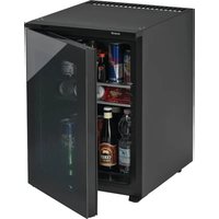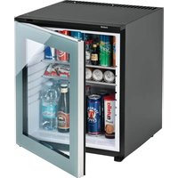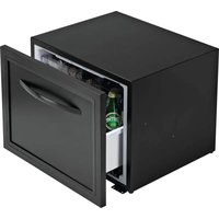
KD 50 ECOSMART - Fridge Indel B - Free user manual and instructions
Find the device manual for free KD 50 ECOSMART Indel B in PDF.


User questions about KD 50 ECOSMART Indel B
0 question about this device. Answer the ones you know or ask your own.
Ask a new question about this device
Download the instructions for your Fridge in PDF format for free! Find your manual KD 50 ECOSMART - Indel B and take your electronic device back in hand. On this page are published all the documents necessary for the use of your device. KD 50 ECOSMART by Indel B.
USER MANUAL KD 50 ECOSMART Indel B
natural_image
Black rectangular box with a white handle, no visible text or symbolstext_image
Diagram of a device with labeled components: 1, 2, and 3, showing a rectangular frame with a circular button and a horizontal bar.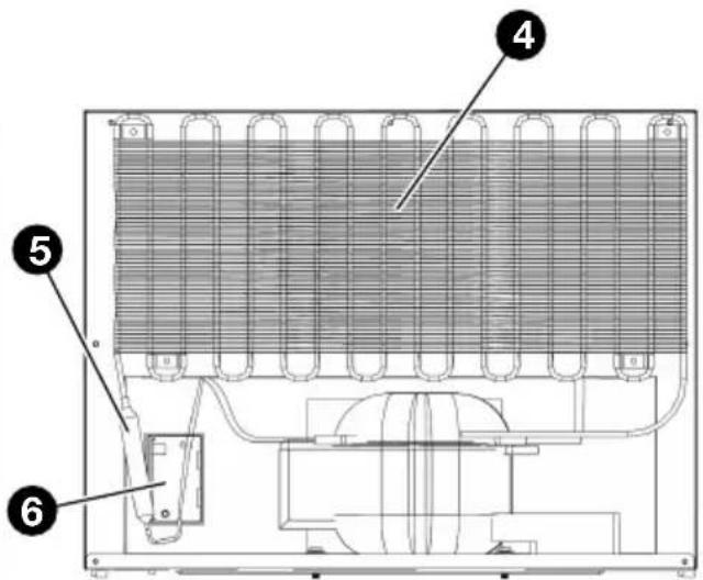
text_image
Technical diagram of an appliance cooling system with numbered components labeled 4, 5, and 6VISTA FRONTALE VISTA POSTERIORE
text_image
Technical diagram of a device casing with labeled components, showing internal compartments and mounting points.VISTA FRONTALE INTERNA
text_image
Technical diagram showing labeled components of a structural joint or bracket assembly, with numbered parts 3 and 4.REGOLATORE LUMINOSO E TERMICO
text_image
Technical diagram of a refrigerator with labeled parts, showing internal compartments and mounting holes.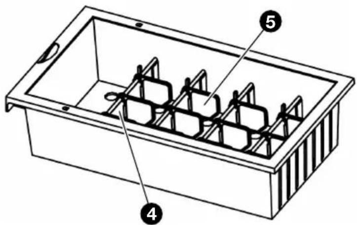
text_image
Technical diagram of a rectangular container with labeled parts 4, 5, and internal structureCASSETTO PICCOLOCASSETTO GRANDE
text_image
Technical diagram showing a 3D structural section with labeled dimensions and directional arrows, likely from an engineering or physics context.natural_image
Technical line drawing of a door frame with attached metal bracket and mounting fixtures (no text or symbols)
SUGGERIMENTO
text_image
Diagram illustrating hospital room ventilation and disinfection process, showing hand holding a card, sleeping person, and refrigerator with 'OFF' label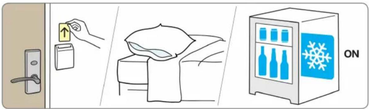
text_image
Illustration showing home security operations: door lock, up arrow, bed with blanket, and refrigerator with snowflake iconITALIANO
text_image
189A1023 Apertonatural_image
Blank white image with a small icon of Wi-Fi signal inside a square frame (no text or symbols)ITALIANO
text_image
SET TIME 8:8:88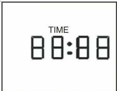
text_image
TIME 8:00:8:00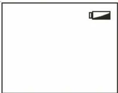
natural_image
Blank white image with a small black battery icon in the top-right corner (no text or symbols)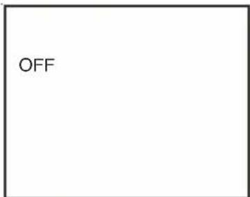
text_image
OFFITALIANO
natural_image
Symbol of a trash bin crossed with no text or labels, representing environmental protection (no text present)TECHNICAL DATA
| MODEL KD 50 ECOSMART | ||
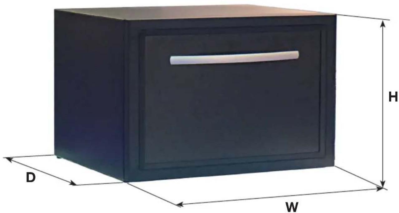
| Dimensions (WxDxH) | 550x540x420 (mm)(Depth include handle) | 550x510x420 (mm)(Depth without hotel door panel) |
| Net weight 25,5 Kg | ||
| Category 2 (Cellar) | ||
| Climate class N | ||
| Rated voltage AC 220/240 V | ||
| Rated power 45 W | ||
| Rated current 0,20 A | ||
| Rated frequency 50 Hz | ||
| Refrigerant R600a (18g) | ||
| Foaming gas C - pentane | ||
natural_image
3D rendering of a dark rectangular box with labeled dimensions D, W, and H (no text or symbols on the box itself)ENGLISH
DESCRIPTION

WARNING!
This product is designed to serve professional purposes (hotels, cruise ships or similar).
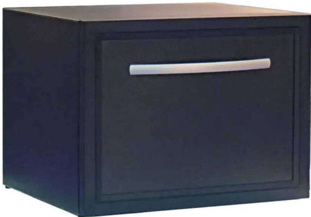
The KD 50 ECOSMART is able to perfectly match the in-room decoration, and bring guests different operating experience.
Please read this user manual carefully prior to using the device.
KD 50 ECOSMART
natural_image
Black wooden cabinet with a white handle, no visible text or symbolsPRODUCT INTRODUCTION
VIEW OF MINIBAR
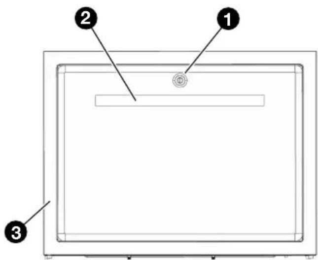
text_image
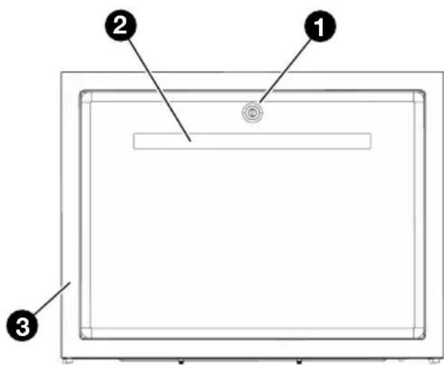
Diagram of a device with labeled components: 1, 2, and 3, showing a rectangular frame with a circular button and a horizontal bar.FRONT VIEW REAR VIEW
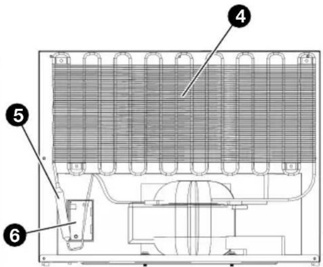
text_image
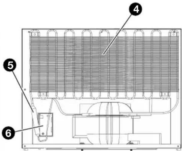
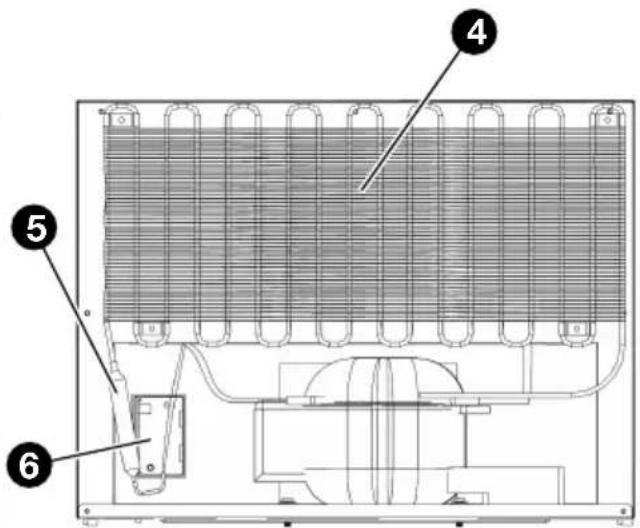
Technical diagram of an appliance cooling system with numbered components labeled 4, 5, and 61 Lock (optional)
2 Handle
3 Door Frame
4 Condenser
5 Dry Filter
6 Main PCB Box
7 Compressor
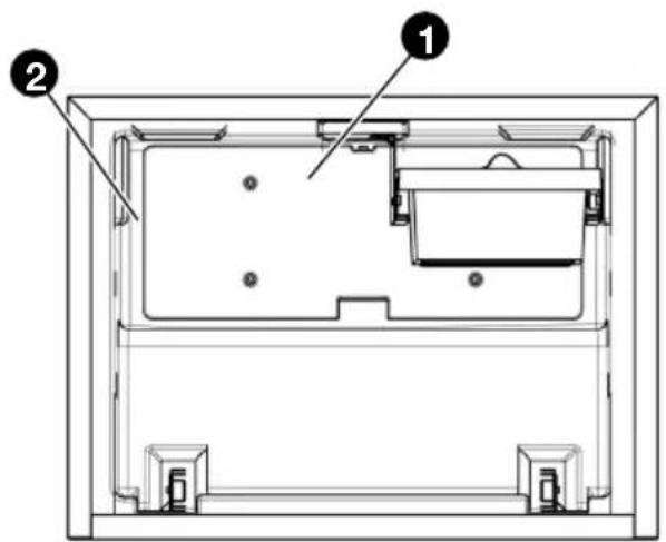
text_image
Technical diagram of a device casing with labeled components, showing internal compartments and mounting points.INSIDE FRONT VIEW
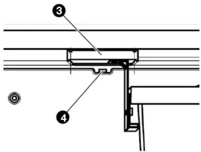
text_image
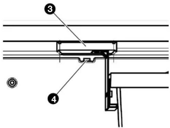
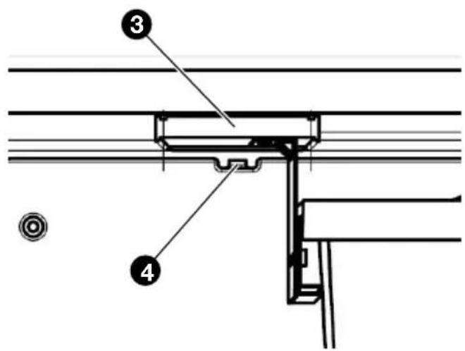
Technical diagram showing labeled components of a structural joint or bracket assembly, with numbered parts 3 and 4.LIGHT & THERMO REGULATOR
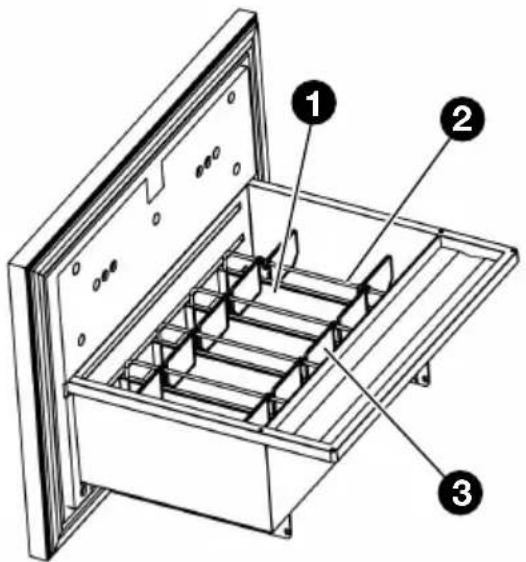
1 Water tank
2 Evaporator
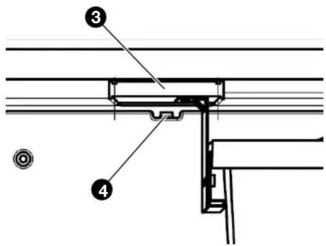
3 Light box
4 Thermo Regulator
ENGLISH
text_image
Technical diagram of a refrigerator with labeled parts, showing internal compartments and mounting points.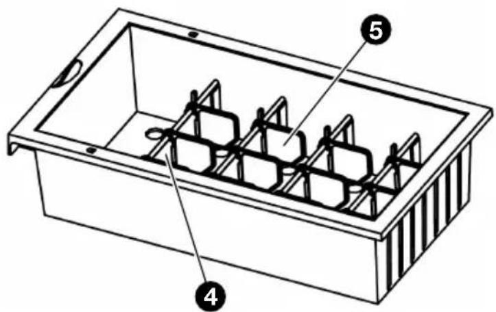
text_image
Technical diagram of a rectangular container with labeled parts 4, 5, and internal structureSMALL DRAWERLARGE DRAWER
1 Separator
2 Metal barr
3 Divider
4 Small Separator
5 Small Divider
COOLING SYSTEM INTRODUCTION
Equipped with a ‘silent’ and high-efficient compressor cooling system and special energy saving system, the KD 50 ECOSMART is able to create a comfortable sleeping environment but with a low operation expense in money, the energy consumption of KD50 ECOSMART is only 35 – 40% of the similar drawer minibars in the market.

WARNING
- Please turn off and disconnect the device from power when you suspect any faulty on cooling system.
- The cooling system is designed air-tightly, in which no additive refrigerant is needed under normal operation. If the appliance fails to refrigerate because of leakage or block, please do not repair it, and do contact INDEL B promptly.
ENGLISH

WARNINGS

WARNING!
Please read this user manual carefully prior to operating the device.

WARNING!
Please connect the device only to the appropriate power supply.

WARNING!
Do not touch the back of the minibar when it is working, to avoid scald.

WARNING!
Children should be supervised by adults when using the minibar.

WARNING!
Keep the air vents on the appliance cover free from obstructions.

WARNING!
Do not use mechanical or electrical devices inside the appliance!

Caution!
Do not move the device when it is working.

Caution!
Always turn off power before cleaning and maintenance.

Attention please!
Always turn off power if the power cable is damaged, and do contact INDEL B.

Attention please!
Do not fill the refrigerant when there is leakage or un-cool, do contact INDEL B.

Attention please!
Do not modify the cooling system and electronic circuit.

Attention please!
The device is designed only for in-room, please do not place the device out-door.

Attention please!
Do not place the device where close to any heat source, for example, heater, oven, and direct sunshine.

Attention please!
Do not place the device where close to humidity, for example, bath room and swimming pool.

Attention please!
Never store explosive substances such as petrol and similar items in the minibar.
ENGLISH
INSTALLATION AND OPERATION
PRODUCT DIMENSION & THE FURNITURE CABINET FOR BUILD-IN
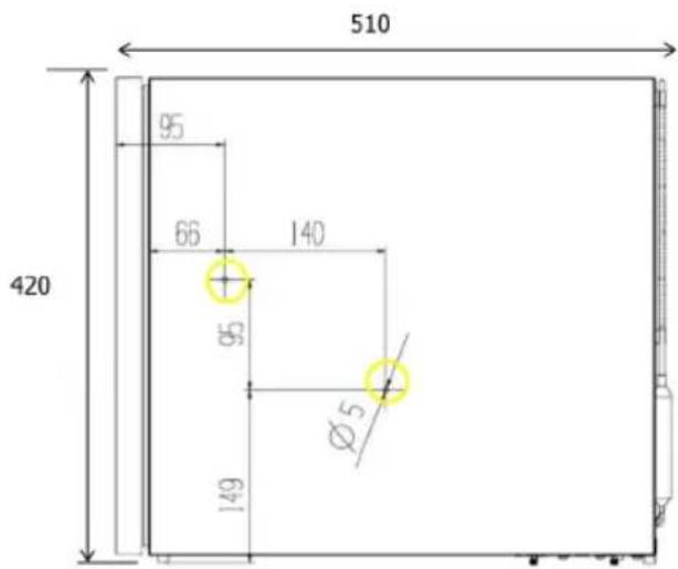
text_image
510 95 66 140 420 95 Ø5 149Product dimension
550 × 540 × 420 mm
(W x D x H, Depth include handle)
550 x 510 x 420 mm
(W x D x H, Depth without hotel door panel)
text_image
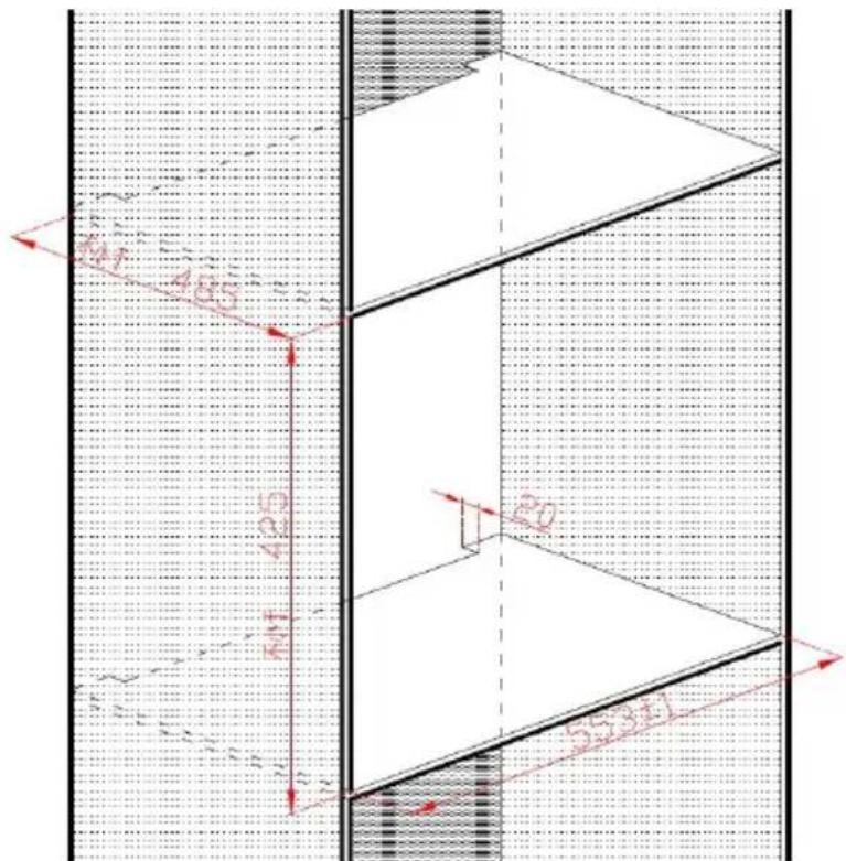
Technical diagram showing a 3D structural section with labeled dimensions and directional arrows, likely from an engineering or CAD context.Prepare the furniture cabinet for built-in
Dimension of the cabinet where install the minibar (built-in)
Width: 552 \~ 554 mm
Height: minimum425 mm
Depth: minimum 485 mm
minimum 485 mm plus the thickness of the hotel wooden door panel
INSTALLATION
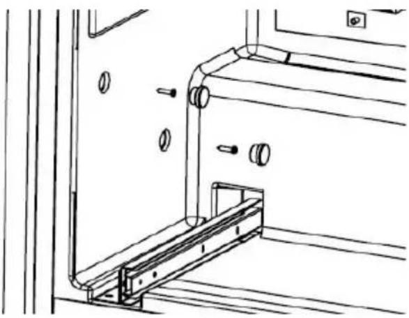
- Remove the caps (2 pcs each side)
• Fix the cabinet with screws (2 pcs each side) - Insert the caps
natural_image
Technical line drawing of a mechanical assembly with mounting brackets and a curved pipe (no text or symbols)
WARM SUGGESTION
- No need to remove the drawer when installation.
- Confirm the position is right before screw in.
VENTILATION
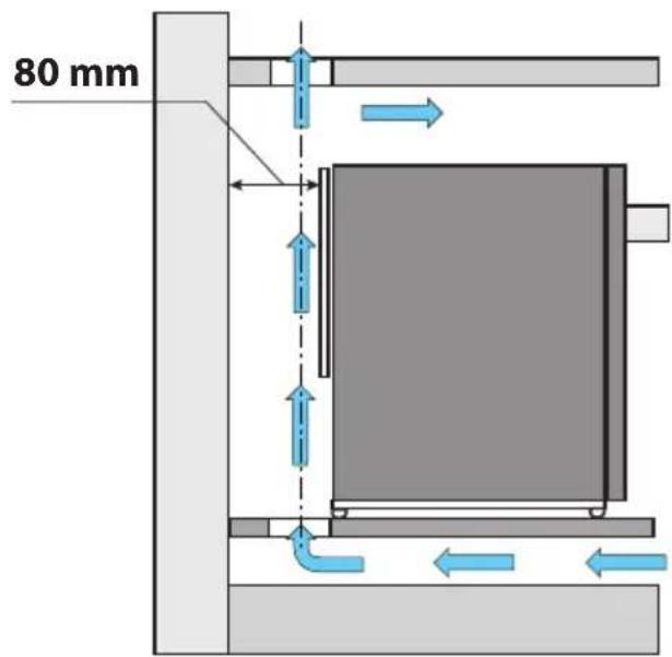
The compressor cooling system lets out heat and needs good ventilation. Therefore places with bad ventilation are not very suitable. The Minibar must be installed in a place with an opening which guarantees the necessary exchange of air, and it is of the utmost importance not to cover up or obstruct the grids which provide the device with proper ventilation. One must also avoid positioning it in a place which is directly exposed to sunlight or to other heat sources.
text_image
80 mm
WARNING
You must fit the Minibar into the cabinet, guaranteeing a cross section at the air inlet and outlet of at least 200 cm ^4 .
ENGLISH
DOOR PANEL INSTRUCTION
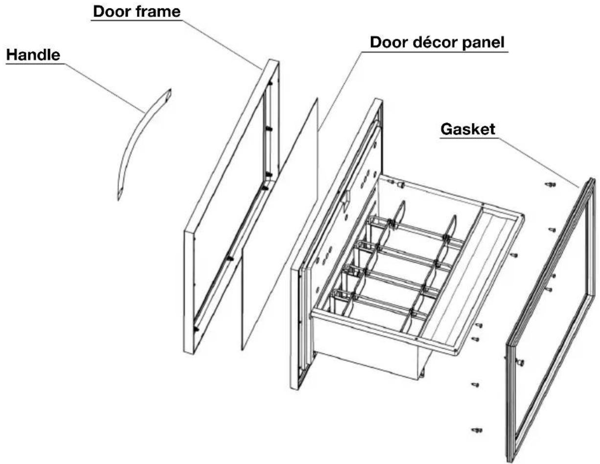
INSTALLATION OF FURNITURE WOODEN PANEL FOR V1
text_image
Handle Door frame Door décor panel Gasket- Remove the door gasket.
- Remove the caps of handle holes.
- Loose the handle fixation screws and remove the handle.
- Loose the door frame fixation screws and remove the door frame.
• Change the door décor panel.
• Install the door frame with screws.
• Install the handle with screws. - insert the caps of handle holes.
• Install the door gasket.
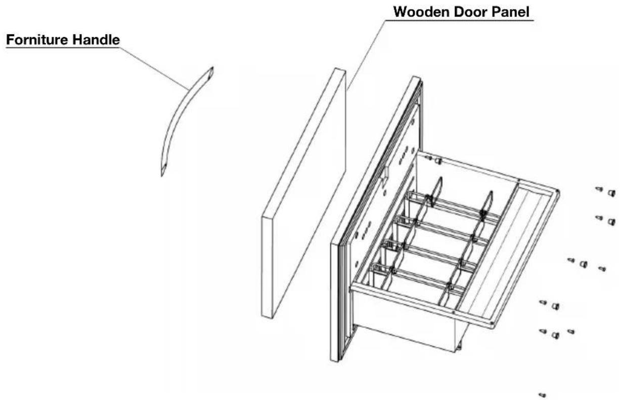
INSTALLATION OF FURNITURE WOODEN PANEL FOR V2
text_image
Forniture Handle Wooden Door Panel- Remove the large drawer.
- Remove the caps of wooden panel fixation holes (8 pcs).
• Fix the wooden door panel with screws inside-out (8 pcs). - insert the caps of the holes (8 pcs).
• Install the large drawer. - Check the gasket whether it is fully sealing.
- Adjust the door, if not.
The hotel's wooden door panel has to be in accordance with the below conditions:
Max. weight: 2 kg
Thickness: 20 mm
Installation: Fixed with 8 screws inside out (Red Circle, in P4)
Lock hole drilling: Diameter of 28mm (GreenCircle, in P4)
Handle drilling: Fixed with 2 screws inside out (Blue Circle, in P4)
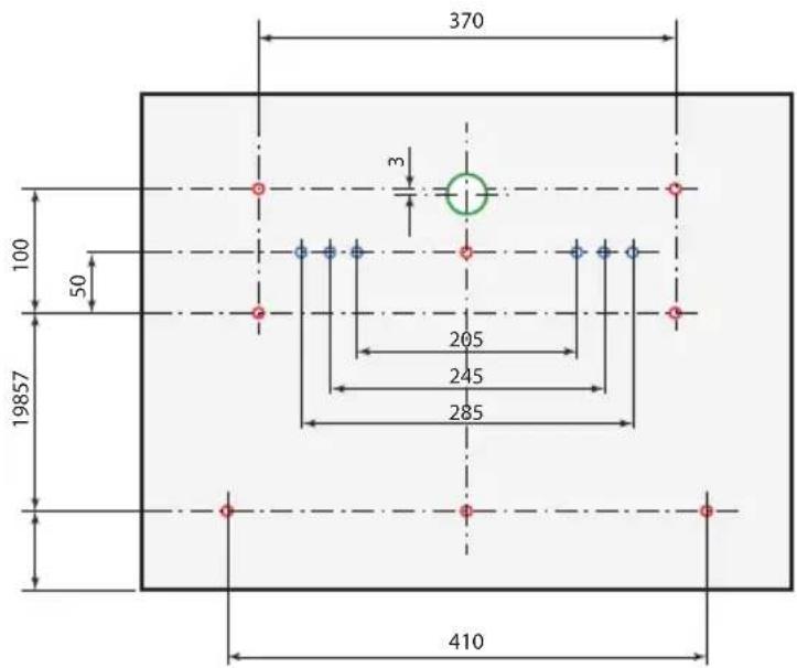
text_image
370 100 50 19857 205 245 285 410ENGLISH
CONNECT TO ELECTRICITY SUPPLY
Please insert the plug into proper socket with earth wire. Upon connection of power supply, the minibar would start to work. It may take 3 - 5 hours before the minibar reaches the desired temperature setting after the first plug-in, depends on quantity of item stored and the temperature of ambient.

ATTENTION
- Check whether the parameters relating to the voltage and power stated in the label of the minibar are proper. Otherwise, please contact INDEL B as soon as possible.
- The device must be powered by constant power supply.
DRAWERS INTRODUCTION
• Large drawer for bottles and cans
305 x 408 x 243 mm (W x D x H), maximum height is 300 mm
• Small drawer for miniature bottles and snacks
110 x 150 x 295 mm (W x D x H), maximum height is 118 mm

WARNING
KD 50 ECOSMART belongs to the category of non-fresh food cellar, suitable for storing beverage, packing snacks (biscuit & chocolate). Please do not store fresh meet, cooked food, and medicine.
GENERAL INFORMATION
KD 50 ECOSMART have three operations methods:
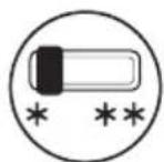
STANDARD: a switch selects the options of minimum and maximum cold. By setting the thermostat, the equipment operates like a standard refrigerator, with electronic defrosting.
TIMER: used to program the compressor operating time.

SMART SYSTEM: it detects the presence of the guest in the room and activates the compressor when the guest goes out.
K ECOSMART is set from factory on STANDARD operation method.
ENGLISH
DESCRIPTION AND OPERATION
STANDARD operation method: functioning
It is possible to adjust this cooling temperature inside the Minibar using the switch on the front of the Minibar:
• the Minibar is off when in position "0"
• the Minibar operates at a higher (reduced cooling) internal constant temperature when in position "*"
- the Minibar operates at a lower (increased cooling) internal constant temperature when in position ***
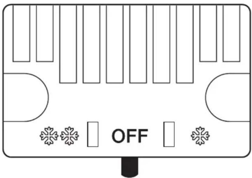
text_image
OFFTIMER operation method: functioning
See TIMER operation method: USE
ENGLISH
SMART SYSTEM operation method: Functioning
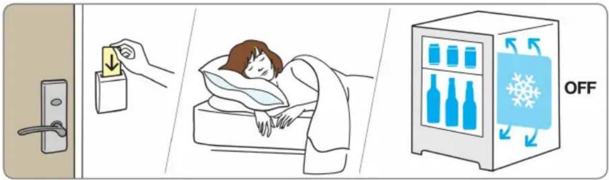
The SMART SYSTEM controls the turning on and off of the compressor based on the presence or absence of the guest in the room. The use of the SMART SYSTEM requires the presence in the room of an Energy Saver device: a card-holder designed to save energy.
The guest enters the room and inserts the card into the card holder; the Energy Saver device sends a signal to the SMART SYSTEM to indicate that a guest is present in the room and the minibar compressor stops (the products inside the minibar remain cold for a long time due to the cold released by the coldholding plate). When the guest leaves the room and removes the card from the Energy Saver holder, another signal is sent to the SMART SYSTEM and the minibar turns on again. If the guest remains in the room for many hours and the cold accumulated in the eutectic plate runs out, the minibar turns on automatically to keep the products cold. If the room is not occupied for a long time, the minibar operates in high energy saving mode.

Attention!
With the SMART SYSTEM operation method, timer and standard operation methods are not used.
text_image
Diagram illustrating hospital room ventilation and storage, showing hand placing a card into a door, sleeping in bed, and refrigeration with 'OFF' label.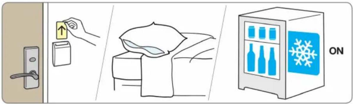
text_image
Diagram illustrating home security features: door lock, up arrow, refrigerator with snowflake, and storage bag with blanket.ENGLISH
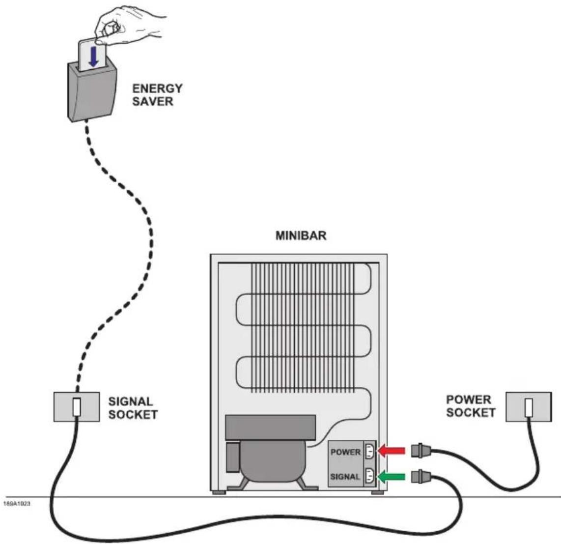
There are two power supply plugs on the back of the Minibar.
Connect the “POWER” plug to the socket in the room specifically for the Minibar (socket not connected to the energy saving system).
Connect the "SIGNAL" plug to any socket connected to the energy saving system (Energy saver).
NOTE: The KD 50 ECOSMART operates in STANDARD/TIMER mode where the "SIGNAL" plug is not connected. Standard mode refers to operation not relative to identification of the Guest in the room and operation which is regulated by the temperature selected by the Client using the switch described above.

Attention!
If the POWER and SIGNAL cables are connected in reverse, the fridge will operate whilst the guest is in the room and will switch itself off when the guest leaves the room.
To confirm that the connection is correct, check that the light illuminates when opening the Minibar door subsequent to checking that:
1) the energy saving system (Energy saver) is not functioning and that the smart card has not been inserted
2) the Minibar is on (the temperature switch at the front of the Minibar must not be in position "0").
In the instance that the light does not illuminate, invert the connection of the two power cables.
flowchart
graph TD
    A["ENERGY SAVER"] --> B["SIGNAL SOCKET"]
    B --> C["MINIBAR"]
    C --> D["POWER SOCKET"]
    C --> E["SIGNAL"]
    style A fill:#f9f,stroke:#333
    style B fill:#ccf,stroke:#333
    style C fill:#cfc,stroke:#333
    style D fill:#fcc,stroke:#333
    style E fill:#cff,stroke:#333
The Minibars of the K Ecosmart series are equipped with a pre-set thermostat located on the back of the refrigerator (the temperature has already been adjusted to the correct operating levels). You can select the duration of the cooling cycles using the remote control. When the Minibar is connected to power supply, it automatically turns on using the mechanical thermostat functions.
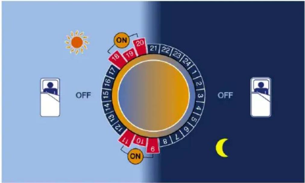
Operating cycles of K Ecosmart compressor unit controlled by the electronic timer
radar
| Hour | Value | |---|---| | 0 | 18 | | 1 | 19 | | 2 | 20 | | 3 | 21 | | 4 | 22 | | 5 | 23 | | 6 | 24 | | 7 | 1 | | 8 | 6 | | 9 | 7 | | 10 | 8 | | 11 | 10 | | 12 | 11 | | 13 | 12 | | 14 | 13 | | 15 | 14 | | 16 | 15 | | 17 | 16 | | 18 | OFF (sun icon) | | 19 | OFF (sun icon) | | 20 | OFF (sun icon) | | 21 | OFF (sun icon) | | 22 | OFF (sun icon) | | 23 | OFF (sun icon) | | 24 | OFF (sun icon) |ON
The compressor is in operation to cool the contents of Minibar and to freeze the eutectic plate (6 hours over 24 hour are sufficient).
The compressor is Off and the cooling energy stored in the holding plate maintains the inside Minibar temperature. The Minibar is completely noiseless during the night.
Preset programs for K Ecosmart version, in which a panel can be installed on the door
| PROGRAM W | WORKING TIME AMBIENTE TEMPERATURE | ||
| 1ST CYCLE 2ND CYCLE | |||
| P1 09-12 18-21 | 25°C | ||
| P2 09-13 18-22 | 28°C | ||
| P3 09-14 17-22 | 30°C | ||
| P4 ADJUSTABLE | |||
| OFF SWITCH ON/OFF | |||
Preset programs for K Ecosmart version with glass door
| PROGRAM WORKING TIME AMBIENTE TEMPERATURE | |||
| 1ST CYCLE 2ND CYCLE | |||
| P1 09-14 17-22 ≤ 25°C | |||
| P2 08-14 17-23 ≤ 28°C | |||
| P3 07-14 17-23 ≤ 30°C | |||
| P4 ADJUSTABLE | |||
| OFF SWITCH ON/OFF | |||
ENGLISH
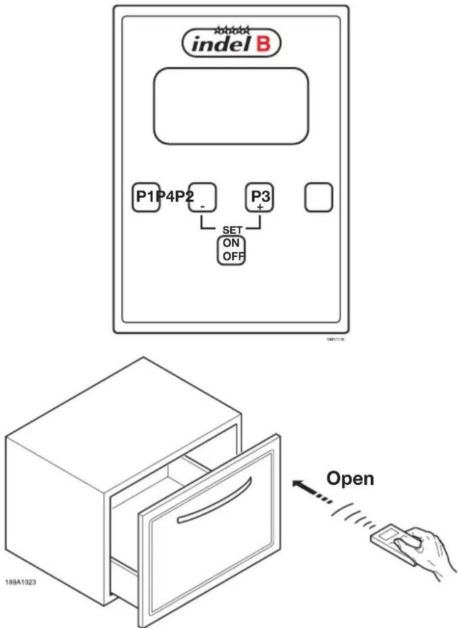
The REMOTE CONTROL
text_image
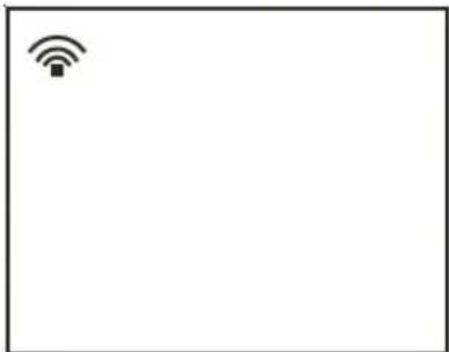
indel B P1P4P2 - P3 + SET ON OFF 189A1023 OpenThe KD equipped with a remote control allows you to set the operation of the compressor to make it work at certain times of day. Each refrigerator has three periods of use which have already been preset, and one (P4) which can be programmed by the user. One can set a maximum of two ON/OFF cycles within 24 hours. The remote control is easy to use. After choosing the programme on the remote control, just point the remote control at the receiver on the inside of the Minibar (at a distance of about 30-40 cm). Keep the button for the chosen programme on the remote control pressed for at least two seconds: the Minibar will start to work. The display will display the following symbol.
natural_image
Simple icon of a Wi-Fi symbol inside a rectangular frame (no text or labels)ENGLISH
SETTING THE TIME
If you press any button from P1 to P4 several times, the display will show the chosen programme and then the time.
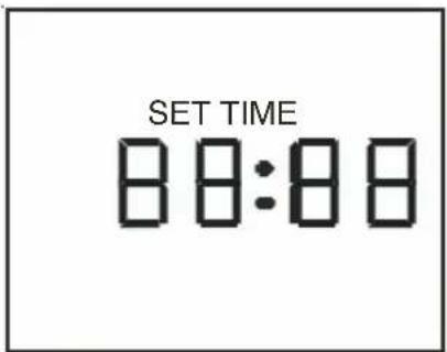
To set the tiem, press P2 and P3 at the same time. The hour digits will start to flash and the display will show the words "set time".
Press - (P2) and + (P3) to set the right time.
To set the minutes, press P1 and then - (P2) and + (P3).
Press P4 to save the new time setting. The display will show the current time.
To set a programme (P1, P2, P3 or P4) on the Minibar, press the button of the chosen programme for at least 2 seconds.
If the batteries have run out, the display will show this symbol:
Press ON/OFF to turn the Minibar off. The display will show "Off". To enable the remote control again, press the ON/OFF key.
text_image
SET TIME 88:88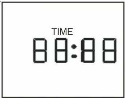
text_image
TIME 88:88
natural_image
Simple line drawing of a battery icon on a plain background (no text or symbols)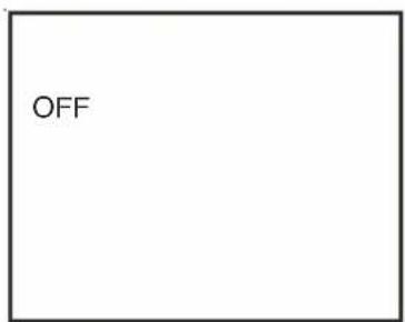
text_image
OFF
Attention!
If the mains power supply is cut off for less than 48 hours, the Minibar turns on again using the previously set program. If the mains power supply is cut off for more than 48 hours, the Minibar will be operated by the pre-calibrated thermostat. To set a program again, follow the instructions given on THE REMOTE CONTROL.

Attention!
If the power supply is voluntarily cut off, wait at least 15 minutes before turning the refrigerator on again (i.e. before connecting it to mains supply). If not, the compressor could be locked for few minutes before starting its normal operationg.
ENGLISH
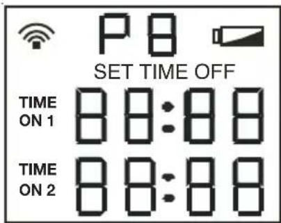
After installing the battery, the display will show the following picture for 5 seconds.
text_image
P B SET TIME OFF TIME ON 1 88:88 TIME ON 2 88:88The display then shows the current hour. if no button is pressed during the following 8 seconds, the words will disappear on the display until another button is pressed.
If you press the buttons P1, P2 or P3, the display will show the pre-set programmes as in the following images. Attention: the programmes P1-P2 and P3 are pre-set and cannot be changed.
The programme P4 allows the user to set two refrigerator working cycles (the first cycle Time on1 –Time off1 and the second cycle Time on2 and Time off2).
To customise the programme P4:
press P1 and P4 simultaneously.
"Time On1" will start to flash on the left.
Use the buttons - (P2) and + (P3) to set the starting time of the first cycle.
Press the button P1 to move ahead to the following fields and then use the - and + buttons again to change the starting and stopping time of the operation cycles of the compressor.
After completing the customisation of the programme, press P4 to save the new settings.
NOTE: After having used the minibar with the TIMER operation method, to pass again in STANDARD operation method, please set P4 on the remote control with all value at 00:00 and push P4 (see instruction SETTING THE TIME).
NOTE: after having used the minibar with the SMART operation method, to pass again in STANDARD operation method, unplug the SIGNAL cable and st P4 on the remote control with a value at 00.00 and push P4 (see instruction SETTING THE TIME).
ENGLISH
ENERGY SAVING SUGGESTIONY
- Ensure sufficient ventilation and shall be kept away from heat source.
• Take items quickly after opening the door and reducing the frequency of opening. - Do not fill the minibar with too many items, or else the cool air circulation would be affected, thus leading to higher power consumption.
- Ensure the door gasket is able to fully seal the gap between the door and the body when the door is closed.
INTERNAL LIGHTING
Low rated power LED light is adopted as the internal light in the minibar, it is high lumen, long service life and energy saving. The lamp is controlled by the opening & closing of door.

WARNING
- The lamp is powered up by DC 12 V, please contact the INDEL B or authorized person in the event that any default is detected.
- Always wearing anti-static gloves or anti-static wrist when dismantling the lighting lamp panel avoid damaging the LED by static electricity.
CLEANING AND MAINTENANCE
CLEANING
Always disconnect the device from the power before cleaning. Soft wet cloth can be used to wipe over the minibar thoroughly. Small quantity of neutral cleanser can also be used, then clean the device with clean dry cloth.

WARNING
- Do not wipe with stimulating cleanser such as hot water, gasoline, alcohol, detergent or high class thinner etc.
- Do not spray the minibar with water directly
MAINTENANCE
- Clean and maintain the device periodically. Do remember to disconnect to power supply prior to cleaning and maintenance.
- Door gasket shall be kept clean all the time in case of going moldy, and shall be free from oil, and be checked regularly for any aging occurs, as to avoid poor sealing effect.
- Clean the condenser at least one time every year.
• Invite qualified staff to perform safety inspection for the electric circuit at least one time every year.
ENGLISH
ONLY FOR SALES WITHIN THE EUROPEAN COMMUNITY (EU)
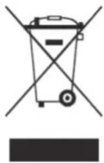
This appliance is marked according to the European Directive 2012/19 / EU (WEEE). The symbol on the product indicates that this product should not be treated as household waste.
Ensure that this product is not entered as part of the flows of municipal waste but treated as professional WEEE.
natural_image
Symbol of a trash bin with crossed lines indicating no waste or restriction (no text or labels)DATOS TÉCNICOS
natural_image
Black rectangular box with a white handle, no visible text or symbolstext_image
Diagram of a device with labeled components: 1, 2, and 3, showing a rectangular frame with a circular button and a horizontal bar.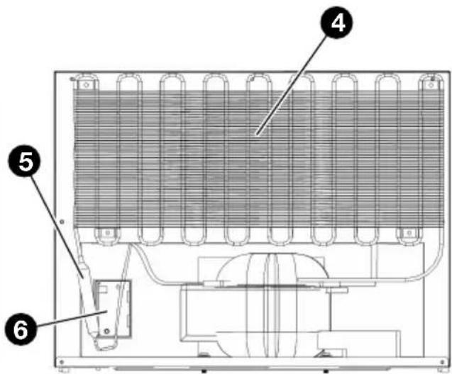
text_image
Technical diagram of an appliance with numbered components, likely a cooling or heating unit assembly.VISTA FRONTAL VISTA TRASERA
text_image
Technical diagram of a device interior with labeled components, showing two numbered parts (1 and 2) for identification.VISTA FRONTAL INTERIOR
text_image
Technical diagram showing labeled components of a structural joint or bracket assembly, with numbered parts 3 and 4.text_image
Technical diagram of a refrigerator with labeled parts including opening, side, and interior compartments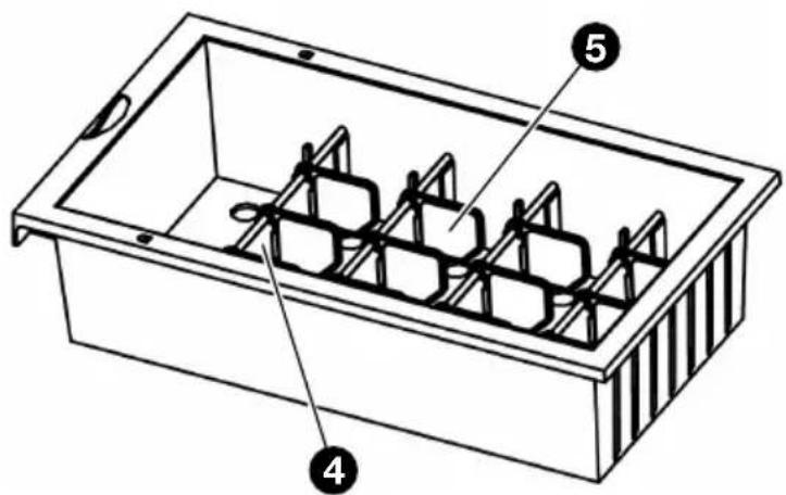
text_image
Technical diagram of a rectangular container with labeled parts 4, 5, and internal structuretext_image
Technical diagram showing a structural cross-section with labeled dimensions and directional arrows, likely from an engineering or architectural drawing.natural_image
Technical line drawing of a mechanical assembly with mounting brackets and a pipe fitting (no text or symbols)
SUGERENCIA
text_image
Medical illustration showing hospital room, patient in bed, and refrigerator with 'OFF' label indicating discharge or disinfection.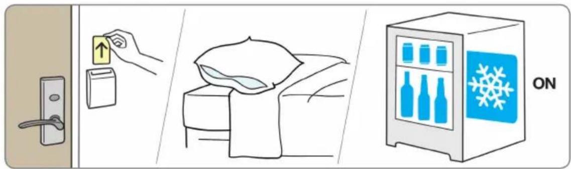
text_image
Diagram illustrating a door lock, a hand placing a card with an arrow, a bed of clothes, and a refrigerator with a snowflake icon labeled 'ON'.ESPAÑOL
text_image
SET TIME 88:88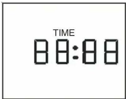
text_image
TIME 88:88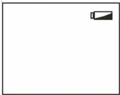
natural_image
Simple line drawing of a battery icon on a plain background (no text or symbols)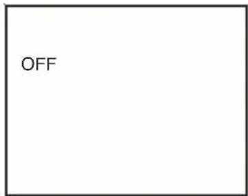
text_image
OFFESPAÑOL
natural_image
Symbol of a trash bin crossed with diagonal lines, no text or labels presentFRANÇAIS
DONNÉES TECHNIQUES
natural_image
3D rendering of a dark rectangular box with labeled dimensions D, W, and H (no text or symbols on the box itself)FRANÇAIS
DESCRIPTION

AVERTISSEMENT!
natural_image
Black rectangular box with a silver handle, no visible text or symbolsINTRODUCTION DES ÉQUIPEMENTS ET SERVICES
VUE DU MINI-BAR
text_image
Diagram of a laptop front panel with labeled components: screen, display, and indicator lightsVUE AVANT VUE ARRIÈRE
text_image
Technical diagram of an appliance cooling system with numbered components labeled 4, 5, and 6text_image
Technical diagram of a device interior with labeled components, showing two numbered parts (1 and 2) for identification.VUE INTÉRIEUR AVANT
text_image
Technical diagram showing labeled components of a structural joint or bracket assembly, with numbered parts 3 and 4.THERMO-RÉGULATEUR ET RÉGULATEUR DE LUMIÈRE
text_image
Technical diagram of a refrigerator with labeled parts including opening, side, and internal compartments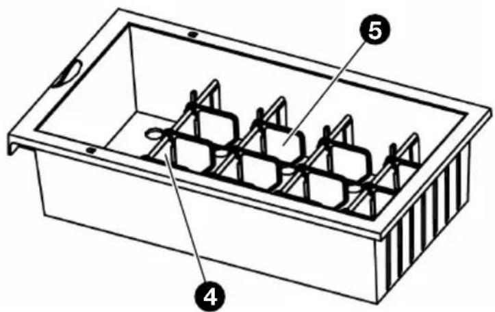
text_image
Technical diagram of a rectangular container with internal compartments and labeled parts 4 and 5PETIT TIROIRGRAND TIROIR
text_image
Technical diagram showing a 3D grid with labeled axes and red arrows indicating directional flow or movement, possibly representing a technical or engineering concept.natural_image
Technical line drawing of a door frame assembly with mounting fixtures and a curved pipe (no text or symbols)
SEILS UTILES
text_image
Diagram illustrating hospital room ventilation and healthcare system with labeled components: door, refrigerator, bed, and refrigerant unit.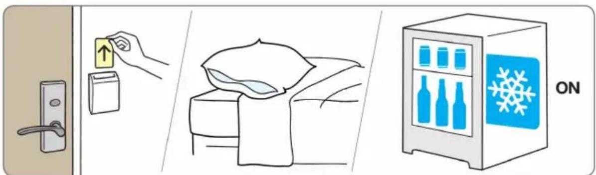
text_image
Diagram illustrating home security features including door lock, up arrow, bed with blanket, and refrigerator with snowflake iconFRANÇAIS
flowchart
graph TD
    A["ENERGY SAVER"] --> B["SIGNAL SOCKET"]
    B --> C["MINIBAR"]
    C --> D["POWER SOCKET"]
    D --> E["16A/123"]
FRANÇAIS
UTILISATION DU TIMER
radar
| Hour | Value | |---|---| | 0 | 18 | | 1 | 19 | | 2 | 20 | | 3 | 21 | | 4 | 22 | | 5 | 23 | | 6 | 24 | | 7 | 1 | | 8 | 7 | | 9 | OFF | | 10 | ON | | 11 | ON | | 12 | ON | | 13 | ON | | 14 | ON | | 15 | ON | | 16 | ON | | 17 | ON | | 18 | OFF | | 19 | OFF | | 20 | OFF | | 21 | OFF | | 22 | OFF | | 23 | OFF | | 24 | OFF |ON
natural_image
Simple icon of a Wi-Fi symbol with signal waves, no text or labels presentFRANÇAIS
MISE À L'hEURE
text_image
SET TIME 88:88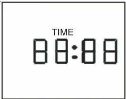
text_image
TIME 88:88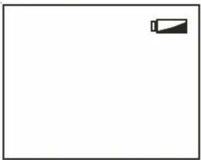
natural_image
Simple line drawing of a battery icon on a plain background (no text or symbols)natural_image
Symbol of a trash bin crossed with diagonal lines, no text or labels presentTEChNISChE DATEN
natural_image
3D diagram of a dark rectangular box with labeled dimensions T, B, and H (no text or symbols on the box itself)DEUTSCH
BESChREIBUNG

WARNUNG!
natural_image
Black rectangular box with a white handle, no visible text or symbolsPRODUKTANLEITUNG
ANSICHT DER MINIBAR

text_image
Diagram of a device with labeled components: 1, 2, and 3, showing a rectangular frame with a circular button and a horizontal bar.VORDERANSICHT
text_image
Technical diagram of an appliance cooling system with numbered components labeled 4, 5, and 6HINTENANSICHT
text_image
Technical diagram of a device rear panel with labeled components, showing internal structure and mounting points.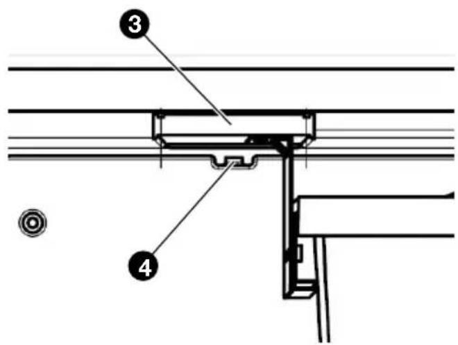
text_image
Technical diagram showing labeled components of a structural joint or bracket assembly, with numbered parts 3 and 4.text_image
Technical diagram of a refrigerator with labeled parts including opening, side, and interior compartments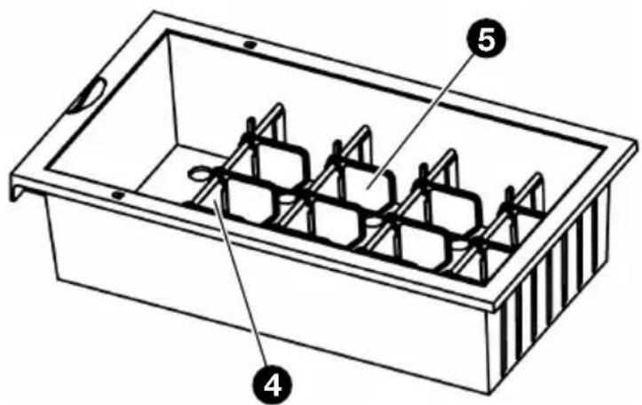
text_image
Technical diagram of a rectangular container with internal compartments and labeled parts 4 and 5text_image
Technical diagram showing a 3D structural section with labeled dimensions and directional arrows, likely from an engineering or engineering drawing.natural_image
Technical line drawing of a door frame with attached metal bracket and pipe fittings (no text or symbols)
EMPFEHLUNGEN
text_image
Diagram illustrating hospital room ventilation and storage mechanism, showing door, hand placing, bed with sleeping person, and refrigerator with water drop.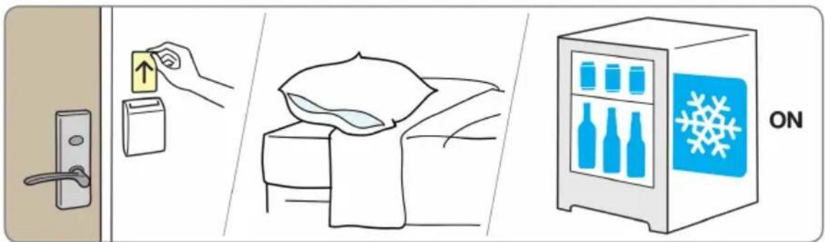
text_image
Diagram illustrating home security features including door lock, up arrow, refrigerator with snowflake, and bed arrangement with bagDEUTSCH
text_image
SET TIME 88:88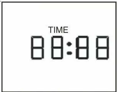
text_image
TIME 88:88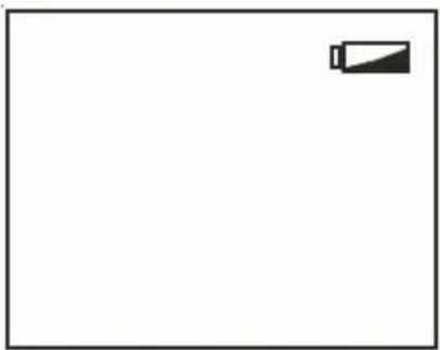
natural_image
Simple line drawing of a battery icon on a plain background (no text or symbols)