
CCBPW12Q - Screwdriver Cleco - Free user manual and instructions
Find the device manual for free CCBPW12Q Cleco in PDF.

| Product Type | Industrial Cordless Screwdriver |
| Model | CCBPW12Q (pistol variant) |
| Brand | Cleco |
| Dimensions (L x H) | 339 x 204 mm (approx., depending on variant) |
| Weight (without battery) | Approx. 3.36 kg (CCBPWN200D6 variant) |
| Power Supply | Lithium-ion battery 18 V (2.0 Ah or 5.0 Ah) |
| Torque Range | 40 – 195 Nm (depending on variant) |
| No-load Speed | 42 rpm (CCBPWN200D6 variant) |
| Rated Power | 260 W |
| Communication | WLAN and Bluetooth 4.0 |
| Display | LED color screen (white/green/red) |
| Work Light | LED (blue/green/red) |
| Main Functions | Screw tightening/loosening, torque control, autonomous or controlled mode |
| Safety | Reaction support, additional handle, safety stop (Stay Alive) |
| Maintenance | Daily visual inspection, send to authorized service every 500,000 cycles or 1 year |
| Cleaning | Clean with a dry cloth, no aggressive liquids |
| Spare Parts and Repairability | Spare parts through authorized service; do not disassemble yourself |
| Operating Environment | Indoor only, 0-40 °C, IP40 |
| Storage | -25 to 65 °C, humidity 10-90% without condensation |
| General Information | CE, UKCA, FCC certifications; manual available in multiple languages |
Frequently Asked Questions - CCBPW12Q Cleco
User questions about CCBPW12Q Cleco
0 question about this device. Answer the ones you know or ask your own.
Ask a new question about this device
Download the instructions for your Screwdriver in PDF format for free! Find your manual CCBPW12Q - Cleco and take your electronic device back in hand. On this page are published all the documents necessary for the use of your device. CCBPW12Q by Cleco.
USER MANUAL CCBPW12Q Cleco
natural_image
Two orange Cleco-based handheld devices with metal clamps and control knobs, shown from different angles (no visible text or symbols on the devices themselves)EN Instruction Manual | Cordless Assembly Tool – High Torque
Copyright © Apex Tool Group, 2025
No part of this document may be reproduced in any way or in any form, in whole or in part, or in a natural or machine-readable language, or transmitted on electronic, mechanical, optical, or other media, without the express permission of the Apex Tool Group.
Disclaimer
Apex Tool Group reserves the right to modify, supplement, or improve this document or the product without prior notice.
Trademark
Cleco is a registered trademark of Apex Brands, Inc.
Manufacturer
Apex Tool Group
670 Industrial Drive
Lexington, SC 29072
USA
Importer
Apex Tool Group GmbH
Industriestraße 1
73463 Westhausen
Germany
Content
EN
1 About this Document....6
2 Safety 6
2.1 Warnings and Notices 6
2.2 Symbols on the Product 7
2.3 Intended Use 7
2.4 Foreseeable misuse....7
2.5 Operator Training 7
2.6 Standards 7
2.7 General Power Tool Safety Warnings....7
2.8 Specific Safety Instructions for Power Tools....9
3 Items Supplied....9
4 Transport / Storage 9
5 Product Description....9
5.1 Reaction Bar....10
5.2 Additional Handle 10
6 Before Initial Operation....10
6.1 Use Reaction Bar 11
6.2 Limitation when using high torque / soft screw joint....11
7 Maintenance....11
8 Technical Data 12
8.1 Right Angle....12
8.2 Pistol....12
8.3 Ambient conditions 12
8.4 Emissions 13
9 Troubleshooting....13
10 Disposal....15
DE
4 Transport / stockage....42
This document is intended for qualified employees responsible for installation and maintenance (installer, maintenance technician, service, operator).
It contains information
• for safe and appropriate handling of the product.
- on function.
• to technical data and maintenance.
• for troubleshooting.
The original language of this document is German.
Information about ordering spare parts is not included. See separate Parts Manual.
Programming instructions are not included. See separate programming instructions for this.
Other Documents
| Number | Document |
| CE-1022 | EU Declaration of conformity – Cell-Core |
| P1730PM | Programming Manual – Tightening Sequences |
| P2280PM | Programming Manual – S168813 mPro400GC(D) & mPro200GC(-AP) |
| P2372JH | Installation Instruction – S168688 Live-Wire Utilities |
| P2398PM | Programming Manual – CCBA & CTBP |
| P2402KA | Quick Installation Guide – CCBA & CTBP Data Transmission |
| P2403HW | Hardware Description – mPro200GC(-AP) |
Symbols in the Text
italic Menu options (e.g., Diagnostics) input fields, check boxes, radio buttons or dropdown menus.
Indicates selection of a menu option from a menu, e.g., File > Print.
<...> Specifies switches, pushbuttons or the keys of an external keyboard, e.g.,
Courier Indicates Filenames and paths, e.g., setup.exe.
• Indicates lists, level 1.
- Indicates lists, level 2.
a) Indicates options.
b)
Indicates results.
-
(...) Indicates action steps.
-
(...)
▶ Indicates single action steps.
2 Safety
▶ Read all safety warnings and instructions. Failure to follow the directions and safety instructions could result in an electric shocks, burns and/or serious injuries.
▶ Keep this document in a safe place for future reference!
▶ These safety instructions must be accessible at all times to all persons who use the product.
2.1 Warnings and Notices
Warning notes are identified by a signal word and a pictogram:
- The signal word describes the severity and probability of the impending danger.
• The pictogram describes the type of danger.

Danger
A symbol combined with the word Danger indicates a hazard with a high level of risk which, if not avoided, will result in death or serious injury.

Warning
A symbol combined with the word Warning indicates a hazard with a medium level of risk which, if not avoided, could result in death or serious injury.

Caution
A symbol combined with the word Caution indicates a hazard with a low level of risk which, if not avoided, could result in minor or moderate injury.

Note
A symbol combined with the word Note indicates a potentially harmful situation which, if not avoided, could result in damage to property or the environment.

General instructions include application tips and useful information, but no warnings against hazards.
Structure Of Warnings

Caution
Type and source of danger. Possible consequences of non-observance.
▶ Measures to avoid danger.
2.2 Symbols on the Product

Electric voltage

Read the operating instructions carefully

CE compliant
The product corresponds to the prescribed technical requirements in Europe.

UKCA compliant.
The product corresponds to the prescribed technical requirements in Great Britain.

Observe and comply with all local disposal guidelines for all components of this equipment and it's packaging.

Unexpected tool movement due to reaction forces or breakage of drive square or reaction bar may cause injuries. There is a risk of crushing between the reaction bar and work piece. Keep hands away from reaction bar. Keep hands away from tool output.
2.3 Intended Use
The user is liable for any damage caused by improper use. Use the product only under the following conditions:
▶ Only use in industrial tightening processes.
▶ Only use in conjunction with the components listed in the EU Declaration of Conformity.
▶ Use under the specified ambient conditions.
▶ Operate within the power range specified in the technical data.
▶ Use with the correctly set tool parameters.
▶ Use in environments with EMC Limit Class A (electromagnetic immunity for industrial environments).
▶ With the recommended battery and charger.
2.4 Foreseeable misuse
▶ DO NOT use the product as a hammer.
▶ DO NOT use a controller other than the one listed in the EC Declaration of Conformity.
▶ DO NOT use the product in areas where there is a risk of explosion.
▶ DO NOT use the product in damp spaces or outdoors.
▶ DO NOT disassemble or modify the product.
2.5 Operator Training
The tightening system may only be put into operation, set up and maintained by personnel who have been trained and qualified by the Apex Tool Group.
The product has been preset by the Apex Tool Group.
Changes to the factory settings may only be carried out by a specialist ^1 .
The owner/operator must ensure that new operating and maintenance personnel are instructed in the operation and servicing of the tightening system to the same extent and with the same care.
Personnel undergoing schooling/training/instruction may only work with the tightening system under the supervision of an experienced person.
Personal Protective Equipment
▶ When working with rotating parts, it is not permitted to wear gloves.
➢ Recommendation: Freely rotating u-GUARD protected tightening tools from APEX.
▶ Wear a hair net, if necessary.
2.6 Standards
It is mandatory that national, state, and local codes and standards be followed.
FCC- and ISED Compliance
This product complies with Part 15 of the FCC Rules. Any changes or modifications not expressly approved by the manufacturer could void the user's authority to operate this product. Operation is subject to the following two conditions:
• This product may not cause harmful interference.
- This product must accept any interference received, including interference that may cause undesired operation.
FCC Responsible party
Name: William Cain
Position: Director, R&D
Address: 670 Industrial Drive
Lexington, SC 29072
United States
This product has been tested and found to comply with the limits for a Class A digital device, pursuant to Part 15 of the FCC Rules. These limits are designed to provide reasonable protection against harmful interference when the product is operated in a commercial environment. This product generates, uses, and can radiate radio frequency energy and, if not installed and used in accordance with the instruction manual, may cause harmful interference to radio communications.
Operation of this product in a residential area is likely to cause harmful interference in which case the user will be required to correct the interference at his own expense.
2.7 General Power Tool Safety Warnings

WARNING Read all safety warnings, instructions, strations and specifications provided with this power tool. Failure to follow all instructions listed below may result in electric shock, fire and/or serious injury.
Save all warnings and instructions for future reference.
The term "power tool" in the warnings refers to mains-operated (corded) power tool or battery-operated (cordless) power tool.
1 Work area safety
a) Keep work area clean and well lit. Cluttered or dark areas invite accidents.
b) Do not operate power tools in explosive atmospheres, such as in the presence of flammable liquids, gases or dust. Power tools create sparks which may ignite the dust or fumes.
c) Keep children and bystanders away while operating a power tool. Distractions can cause you to lose control.
2 Electrical safety
a) Power tool plugs must match the outlet. Never modify the plug in any way. Do not use any adapter plugs with earthed (grounded) power tools. Unmodified plugs and matching outlets will reduce risk of electric shock.
b) Avoid body contact with earthed or grounded surfaces, such as pipes, radiators, ranges and refrigerators. There is an increased risk of electric shock if your body is earthed or grounded.
c) Do not expose power tools to rain or wet conditions. Water entering a power tool will increase the risk of electric shock.
d) Do not abuse the cord. Never use the cord for carrying, pulling or unplugging the power tool. Keep cord away from heat, oil, sharp edges or moving parts. Damaged or entangled cords increase the risk of electric shock.
e) When operating a power tool outdoors, use an extension cord suitable for outdoor use. Use of a cord suitable for outdoor use reduces the risk of electric shock.
f) If operating a power tool in a damp location is unavoidable, use a residual current device (RCD) protected supply. Use of an RCD reduces the risk of electric shock.
3 Personal Safety
a) Stay alert, watch what you are doing and use common sense when operating a power tool. Do not use a power tool while you are tired or under the influence of drugs, alcohol or medication. A moment of inattention while operating power tools may result in serious personal injury.
b) Use personal protective equipment. Always wear eye protection. Protective equipment such as a dust mask, non-skid safety shoes, hard hat or hearing protection used for appropriate conditions will reduce personal injuries.
c) Prevent unintentional starting. Ensure the switch is in the off position before connecting to power source and/or battery pack, picking up or carrying the tool. Carrying power tools with your finger on the switch or energizing power tools that have the switch on invites accidents.
d) Remove any adjusting key or wrench before turning the power tool on. A wrench or a key left attached to a rotating part of the power tool may result in personal injury.
e) Do not overreach. Keep proper footing and balance at all times. This enables better control of the power tool in unexpected situations.
f) Dress properly. Do not wear loose clothing or jewellery. Keep your hair and clothing away from moving parts. Loose clothes, jewellery or long hair can be caught in moving parts.
g) If devices are provided for the connection of dust extraction and collection facilities, ensure these are connected and properly used. Use of dust collection can reduce dust-related hazards.
h) Do not let familiarity gained from frequent use of tools allow you to become complacent and ignore tool safety principles. A careless action can cause severe injury within a fraction of a second.
4 Power tool use and care
a) Do not force the power tool. Use the correct power tool for your application. The correct power tool will do the job better and safer at the rate for which it was designed.
b) Do not use the power tool if the switch does not turn it on and off. Any power tool that cannot be controlled with the switch is dangerous and must be repaired.
c) Disconnect the plug from the power source and/or remove the battery pack, if detachable, from the power tool before making any adjustments, changing accessories, or storing power tools. Such preventive safety measures reduce the risk of starting the power tool accidentally.
d) Store idle power tools out of the reach of children and do not allow persons unfamiliar with the power tool or these instructions to operate the power tool. Power tools are dangerous in the hands of untrained users.
e) Maintain power tools and accessories. Check for misalignment or binding of moving parts, breakage of parts and any other condition that may affect the power tool's operation. If damaged, have the power tool repaired before use. Many accidents are caused by poorly maintained power tools.
f) Keep cutting tools sharp and clean. Properly maintained cutting tools with sharp cutting edges are less likely to bind and are easier to control.
g) Use the power tool, accessories and tool bits etc. in accordance with these instructions, taking into account the working conditions and the work to be performed. Use of the power tool for operations different from those intended could result in a hazardous situation.
h) Keep handles and grasping surfaces dry, clean and free from oil and grease. Slippery handles and grasping surfaces do not allow for safe handling and control of the tool in unexpected situations.
5 Battery tool use and care
a) Recharge only with the charger specified by the manufacturer. A charger that is suitable for one type of battery pack may create a risk of fire when used with another battery pack.
b) Use power tools only with specifically designated battery packs. Use of any other battery packs may create a risk of injury and fire.
c) When battery pack is not in use, keep it away from other metal objects, like paper clips, coins, keys,
nails, screws or other small metal objects, that can make a connection from one terminal to another. Shorting the battery terminals together may cause burns or a fire.
d) Under abusive conditions, liquid may be ejected from the battery; avoid contact. If contact accidentally occurs, flush with water. If liquid contacts eyes, additionally seek medical help. Liquid ejected from the battery may cause irritation or burns.
e) Do not use a battery pack or tool that is damaged or modified. Damaged or modified batteries may exhibit unpredictable behaviour resulting in fire, explosion or risk of injury.
f) Do not expose a battery pack or tool to fire or excessive temperature. Exposure to fire or temperature above 130 °C may cause explosion.
g) Follow all charging instructions and do not charge the battery pack or tool outside the temperature range specified in the instructions. Charging improperly or at temperatures outside the specified range may damage the battery and increase the risk of fire.
6 Service
a) Have your power tool serviced by a qualified repair person using only identical replacement parts. This will ensure that the safety of the power tool is maintained.
b) Never service damaged battery packs. Service of battery packs should only be performed by the manufacturer or authorized service providers.
2.8 Specific Safety Instructions for Power Tools
The term "power tool" in the warnings refers to mains-operated (corded) power tool or battery-operated (cordless) power tool.
a) Our insulation is not insulation in the sense of VDE standards: Hold the device at the insulated handle surfaces when you perform work where the screw can strike hidden power lines or your own power cable. Contact between the screw and a live power line could energize metal parts of the tool and cause an electric shock.
b) Hold the tool firmly. Be prepared for torque reaction.
c) Reaction bars are recommended in applications with limited space and when using:
- Inline tools used above 4 Nm.
- Pistol tools used above 10 Nm.
- Angle tools used above 60 Nm.
d) NEVER rest your hand on the reaction bar when working.
e) Check that the suspension bail is properly secured to the balancer.
Power Tool Use and Care
▶ Only use wrench sockets that are suitable for use on machinery.
▶ Make sure that the wrench sockets are securely inserted.
▶ Do not attach wrench sockets to the screw head at an angle.
▶ Inspect wrench sockets for visible damage and cracks. Replace damaged wrench sockets immediately.
▶ Do not open the battery.
3 Items Supplied
- Correct tool (without battery)
- Instruction manual
• EU Declaration of conformity - Warranty
• CCBAWN(...): Additional handle
• CCBPWN(...): Suspension bail - Calibration Certificate
4 Transport / Storage
▶ Transport or store the product in its original packaging. The packaging is recyclable.
▶ If the packaging is damaged, check the part for visible damage. Inform the carrier and, if necessary, your Sales & Service Center.
▶ Disconnect the power supply during storage. Refer to see chapter 8.3 Ambient conditions, page 12.
5 Product Description
Control Elements
Battery powered hand held nutrunner used for the tightening / loosening of threaded fasteners:
• Work Light for secondary OK/NOK visual feedback.
- "Stay Alive" function prevents reboot during battery change. Stay alive time = 20 sec.
- On-tool Digital Transducer and Servo provide critical information and eliminate errors.
- Connects easily over WLAN and Bluetooth 4.0.
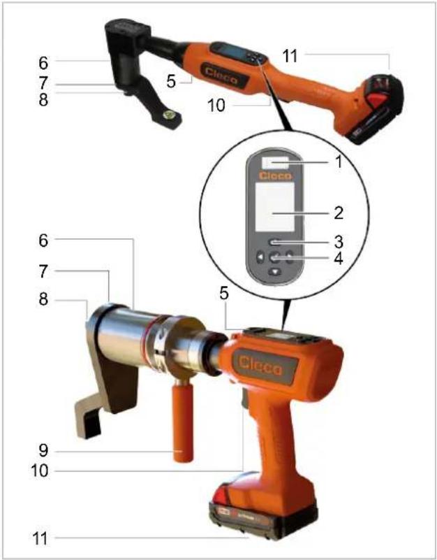
Fig. 1-1: Product Description CCBAWN(...)/CCBPWN(...)
| 1 | Micro USB-B Port |
| 2 | Display |
| 3 | Function Keys |
| 4 | Confirmation button |
| 5 | Work Light |
| 6 | Torque Multiplier |
| 7 | Reaction Bar |
| 8 | Output Square Drive |
| 9 | Additional handle |
| 10 | Start Trigger |
| 11 | Battery pack |
Display
Default settings:
| White | Green | Red |
| Tool running | OK rundown | NOK rundown |
Work Light
Default settings:
| Blue | Green | Red |
| Tool running | OK rundown | NOK rundown |
5.1 Reaction Bar
These tools require a reaction bar! Reaction forces are contained by the reaction bar, so forces are not passed back to the operator.
5.2 Additional Handle
For more controllable use of the hand-held tool.

Warning
Crushing
Unexpected tool movement due to reaction forces, breakage of drive square or reaction bar may cause injuries. There is a risk of crushing between the reaction bar and work piece.
▶ Keep hands away from reaction bar and tool output.
▶ Keep hands away from additional handle.
If necessary, attach a balancer to the additional handle.
6 Before Initial Operation
Charging Battery Pack
Battery pack is supplied partly charged and must be charged completely being used for the first time.
▶ See Original Instructions of Milwaukee charger.
▶ Do not use any other battery packs / chargers than the following:
Battery pack 18 V
| Order No. | Capacity |
| T50-1000497 | 2.0 Ah |
| T50-1000498 | 5.0 Ah |
Charger 18 V
| Order No. | Country | |
| T50-1000499 | North America | 1-Bay |
| T50-1000506 | Europe | |
| T50-1000507 | Brazil | |
| T50-1000543 | Argentina | |
| T50-1000544 | United Kingdom | |
| T50-1000545 | China | |
| T50-1000546 | Japan | |
| T50-1000500 | North America | 6-Bay |
| T50-1000508 | Europe | |
| T50-1000547 | United Kingdom |
Working with controller (mPro-Modus)
▶ Configure the tool, refer to the Programming Manual tool.
▶ Configure WLAN on the controller, refer to the Quick Installation Guide and the Programming Manual mPro(...)GCD.
Stand-alone (FastApp-Modus)
Configure the tool, refer to the Programming Manual – Cordless Assembly Tool – High Torque.
6.1 Use Reaction Bar
In operation, the reaction bar rotates in the opposite direction to the Output Square Drive and must be allowed to rest squarely against a solid object or surface adjacent to the bolt to be tightened. React should be on the end of the reaction bar. When loosening attach the reaction bar on the opposite side.
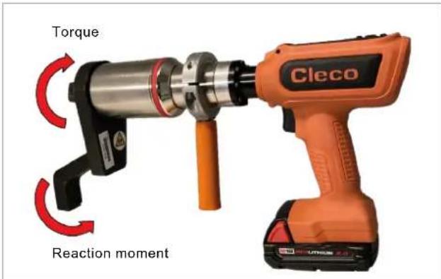
Fig. 1-2: Reaction moment
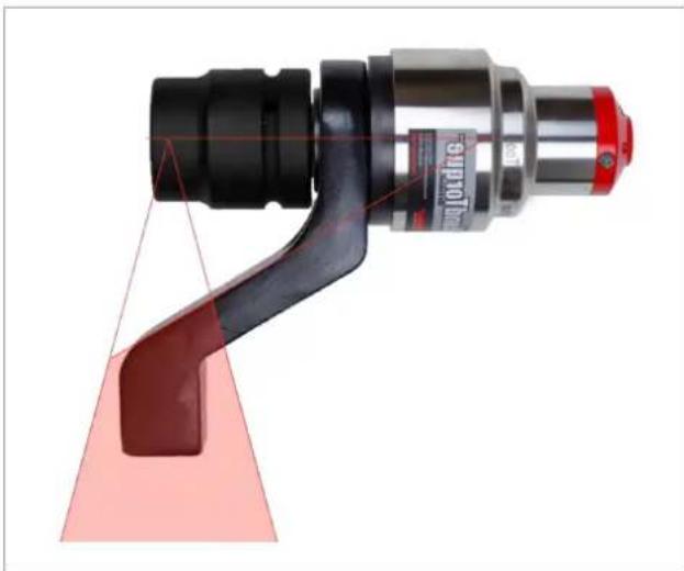
The supplied reaction bar has been designed to give an ideal reaction point when used with a standard length socket. In order to take into account a small difference in the socket length, the reaction recording can have contact at any point, in the shaded area of the illustration see Fig. 1-3: Safe Support Window, page 11.
natural_image
Close-up of a mechanical tool with a red triangular component and black handle, no visible text or symbolsFig. 1-3: Safe Support Window
If an extra long socket is used it may move the reaction bar outside the safe reaction window. The standard reaction bar may need to be extended to ensure it remains wholly within the shaded area.
| Warning | |
| Risk of injuryReaction bar can break due to excessive stress.Torque Reaction should be taken in the shaded areas onlyAfter changing the reaction bar, make sure that it can absorb the maximum load of the tool. | |
| Note | |
| Severe damage to the tool outputDo not use standard square drive extensions. |
| Note |
| Severe damage to the tool output► Do not use standard square drive extensions. |
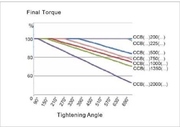
6.2 Limitation when using high torque / soft screw joint
High torques and soft screw joints require a longer break between screw connections, which is why we recommend pre-tightening to increase the effectiveness.
line
| Tightening Angle | CCB(...200)... | CCB(...225)... | CCB(...500)... | CCB(...750)... | CCB(...1000)... | CCB(...1350)... | CCB(...2000)... | | ---------------- | ------------ | ------------ | ------------ | ------------ | ------------- | ------------- | ------------- | | 90° | 100% | 100% | 100% | 100% | 100% | 100% | 100% | | 150° | 100% | 100% | 100% | 100% | 100% | 100% | 100% | | 210° | 100% | 100% | 100% | 100% | 100% | 100% | 100% | | 270° | 100% | 100% | 100% | 100% | 100% | 100% | 100% | | 330° | 100% | 100% | 100% | 100% | 100% | 100% | 100% | | 390° | 100% | 100% | 100% | 100% | 100% | 100% | 100% | | 450° | 100% | 100% | 100% | 100% | 100% | 100% | 100% | | 510° | 100% | 100% | 100% | 100% | 100% | 100% | 100% | | 570° | 100% | 100% | 100% | 100% | 100% | 100% | 100% | | 630° | 100% | 100% | 100% | 100% | 100% | 100% | 100% | | 690° | 100% | 100% | 100% | 100% | 100% | 100% | 100% |Fig. 1-4: Limitation
7 Maintenance
Implement a comprehensive safety maintenance program to provide regular inspection for all phases of tool operation and power supply.
| Maintenance after every ... cycles ^2 | Measures |
| Daily | ▶ Check all connections.▶ Visual inspection for general damage.▶ Perform a general function test and watch out for excessive vibration or unusual noise. |
| 500,000 or at least once a year | ▶ Send the tool to a certified Sales & Service Center for assessment. |
8 Technical Data
8.1 Right Angle
Values do not include battery
| Order no. | Torque Range | Nominal Power | Speed | Weight | Length | Height | Side to Center | Output | |
| Nm(ft-lb)Min. | Nm(ft-lb)Max. | W | r/min | kg(lb) | mm(in) |  |  | ||
| mm(in) | mm(in) | ||||||||
| CCBAWN225NB6 | 45(33.2) | 225(166.0) | 260 | 34 | 4.68(10.32) | 611(24.1) | 234(9.2) | 31.7(1.2) | ■ 3/4" |
| CCBAWN750NB6 | 154(113.6) | 750(553.2) | 260 | 11 | 5(11.0) | 611(24.1) | 261(10.3) | 31.7(1.2) | ■ 3/4" |
| CCBAWN1000NB6 | 200(147.5) | 1000(737.6) | 260 | 7 | 5(11.0) | 611(24.1) | 261(10.3) | 31.7(1.2) | ■ 3/4" |
| CCBAWN1350NB8 | 293(216.1) | 1350(995.7) | 260 | 6 | 5,2(11.5) | 645(25.4) | 292(11.5) | 42.8(1.7) | ■ 1" |
8.2 Pistol
Values do not include battery
| Order No. | Torque Range | Nominal Power | Speed | Weight | Length | Height | Side to Center | Output | |
| Nm(ft-lb)Min. | Nm(ft-lb)Max. | W | rpm | kg(lb) | mm(in) |  mm(in) mm(in) |  mm(in) mm(in) | ||
| CCBPWN200D6 | 40(29.5) | 195(143.8) | 260 | 42 | 3.36(7.41) | 339(13.35) | 204(8.03) | 28(1.10) | ■ 3/4" |
| CCBPWN260D6 80 | (59.0) | 260(191.7) | 260 30 | 3.21 | (7.08) | 339(13.35) | 203(7.997) | 28(1.10) | ■ 3/4" |
| CCBPWN500D6 | 119(87.8) | 500(368.8) | 260 | 14 | 3.58(7.89) | 339(13.35) | 204(8.03) | 28(1.10) | ■ 3/4" |
| CCBPWN750D6 | 155(114.3) | 750(553.2) | 260 | 10 | 3.36(7.41) | 339(13.35) | 204(8.03) | 28(1.10) | ■ 3/4" |
| CCBPWN1000D6 | 214(157.8) | 1000(737.6) | 260 | 8 | 6.38(14.07) | 403(15.87) | 208(8.19) | 40(1.57) | ■ 3/4" |
| CCBPWN1350D8 | 293(216) | 1350(995.7) | 260 | 6 | 6.68(14.73) | 403(15.87) | 208(8.19) | 40(1.57) | ■ 1" |
| CCBPWN2000D8 | 436(321.6) | 2000(1475) | 260 | 4 | 7.23(15.94) | 403(15.87) | 208(8.19) | 40(1.57) | ■ 1" |
8.3 Ambient conditions
| Features | Data |
| Operation site | Indoors |
| Working temperature | 0 °C – 40 °C |
| Storage temperature | -25 °C – 65 °C |
| Type of Cooling | Convection (self-cooling) |
| Relative humidity | 10 % – 90 %, no condensation |
| Working height | Up to 3000 m (9,843 ft) above sea level |
| Degree of protection as per DIN EN60529 (IEC60 529) | IP40 |
| Protection class as per DIN EN 61140 (VDE 0140-1) | II |
8.4 Emissions
| Order No. | Sound Level Free Speed ISO 15744 [dB(A)] | Sound Level Uncertainty | Vibration Level No Load ISO 28927-2 [m/s ^2 ] | Vibration Level Uncertainty |
| CCBAWN225NB6 | < 70 | ±3 | <2.5 | 1.5 |
| CCBAWN750NB6 | < 70 | ±3 | <2.5 | 1.5 |
| CCBAWN1000NB6 | < 70 | ±3 | <2.5 | 1.5 |
| CCBAWN1350NB8 | < 70 | ±3 | <2.5 | 1.5 |
| CCBPWN200D6 | < 70 | ±3 | <2.5 | 1.5 |
| CCBPWN260D6 | < 70 | ±3 | <2.5 | 1.5 |
| CCBPWN500D6 | < 70 | ±3 | <2.5 | 1.5 |
| CCBPWN750D6 | < 70 | ±3 | <2.5 | 1.5 |
| CCBPWN1000D6 | < 70 | ±3 | <2.5 | 1.5 |
| CCBPWN1350D8 | < 70 | ±3 | <2.5 | 1.5 |
| CCBPWN2000D8 | < 70 | ±3 | <2.5 | 1.5 |
9 Troubleshooting
| Problem | Possible cause | Measure |
| Tool does not start. No speed programmed. | ▶ Check Linking group. In the mPro mode, select Navigator> Standard or Navigator> Basic. | |
▶ Check FastApps. In the FastApps mode:  | ||
| Controller is waiting for tool enablement. | ▶ Enable the input Tool Enable or, if not required, deactivate Tool Enable. | |
| Fast-Apps mode disabled. | ▶ Enable FastApps mode:  | |
| Self-identification data are not recognized after tool change. | Accept Tool Settings again:1. Navigator > Tool Setup.2. Select the line with the tool.3. Select Tool Settings> Accept. | |
| Tool not recognized. | Software is incorrect. | ▶ Check controller and measuring card software. |
| FastApps mode is activated. | ▶ Disable FastApps mode to connect to the controller. | |
| Tool is defective. | ▶ Change tool. | |
| Tool doesn't start with counterclockwise rotation activated. | With counterclockwise rotation, parameter for speed is set to 0 ^1 /min. | Parameterize Speed left rotation▶ Select on the controller Navigator > Standard > Tool Groups > Settings For Speed Left Rotation. |
| Tool shuts off prematurely. | Operator releases start trigger before the controller stops the tool. | Make sure that the operator keeps the start trigger pressed throughout the entire sequence. |
| The fastening time exceeds the standard time of 10 seconds. | Increase the fastening time. | |
| Tool exceeds the angle setpoint. | Check the fastening sequence to ensure that the torque shutoff value and/or angle setpoint are correct. Adjust as necessary.Check whether the fastening joint has changed significantly. | |
| Tool does not change speed. | Speed is the same in all stages. | Make sure that the speed in the stages is correct. |
| Warning in the Run Screen: Tool offline! | Tool has not been accepted in the Tool Settings. | Select Navigator > Tool Setup.Select the line with the tool in the tool list and pressPress. |
| Different torque display in the controller and external transducer. | Adjust the torque calibration factor. | Select Navigator > Tool Setup.Select the line with the tool in the tool list and press.Enter the torque calibration factor at Torque Calibration using the following formula:New calibration value = (external value / tool value) x calibration value used. |
| Customer's special attachment was added to tool. The tool memory must be updated. | Reprogram tool memory. | |
| Work light disabled. | Disabled by parameter setting. | Parameterize the tool light on the controller screen: Navigator > Advanced > Tool Group > Extended Tool Settings.To activate the work light: > |
| No-load speed not reached. | Battery voltage is too low. | Use a fully charged battery. |
| Expected number of run-downs is not achieved with one charge of the battery. | Battery is not fully charged. | Use fully charged battery. |
| The warning threshold for undervoltage is not set to the minimum value. | Reduce the Undervoltage (V) on the control screen: Navigator > Tool Setup > Tool Settings > Others > Low Level [V]. | |
| To set the warning threshold: > | ||
| High torque is needed during a fastening sequence, e.g., for coated fasteners. | If a high torque is needed for a longer period of time, e.g., for several turns, the number of run-downs that can be achieved with one battery charge will be significantly reduced. | |
| Battery has too many charging cycles. | After 800 charging cycles, the capacity is reduced to approx. 60%. |
WLAN data communication problems between controller and tool
| Problem | Possible cause | Measure |
| No WLAN data communication between the controller and tool. | The IP address of the tool is not correctly entered in the controller.Tool is already assigned to another controller. | 1. Check on the control screen: Navigator >Tool Setup, whether the IP address of the tool has been entered in the box Type.2. Otherwise, mark the line and.IP address of tool – see Tool in submenuWLAN communication.▶ Check the WLAN settings and make sure that the WLAN settings for the controllers are different. |
| Applies only to WLAN infrastructure customers:▶ Check whether another controller already has a connection to this tool. In other words, another controller is using the same IP address. | ||
| IP address cannot be pinged. | IP address already exists in the network. In this case, the tool will not establish a connection. | ▶ Check the physical connection (RSSI values): [IMAGE] ▶ Check the assigned IP address. |
| Occasional interruptions in WLAN data communication. | Distance between the access point and the tool is too great. | 1. Check signal strength at tool in the sub-menu Signal Strength: [IMAGE] > [IMAGE]2. If necessary, reduce the distance between the access point and the tool. |
| Excessive data traffic on WLAN network. | Reduce data traffic on WLAN network.1. On the Basic control screen, increase the Trigger: Navigator > Basic Application Builder > Trigger Torque.2. Disable the torque graph data transmission on Navigator > Advanced > Controller > General > Trace Recording. For this, select the entry Record in the column Off. |
10 Disposal
Components and auxiliary materials of the product pose risks to the health and the environment. The tool contains components that can be recycled as well as components that must be specially disposed of.
Separate the components of the packing and segregate the different materials before disposing of them.
▶ Follow the locally applicable regulations.

Observe generally valid disposal guidelines such as, in Germany, the Electrical and Electronic Equipment Act (ElektroG) and the Battery Act (BattG).
▶ Dispose of waste battery packs.
▶ Return the battery to your company collection facility or to Sales & Service Center.
▶ Do not dispose of the batterie packs in the household waste or throw them into fire or water.
2.6 Normen/Standards
natural_image
Close-up of a mechanical tool with red and black components, no visible text or symbolsnatural_image
Close-up of a mechanical tool with black and red components, no visible text or symbols2.6 Normes / standards
4 Transport / stockage
natural_image
Close-up of a mechanical tool with a red handle and black shaft, no visible text or symbolsnatural_image
Close-up of a mechanical tool with black and red components, no visible text or symbolsPlease note that all locations may not service all products.
Contact the nearest Cleco® Sales & Service Center for the appropriate facility to handle your service requirements.

Sales Center
Service Center
NORTH AMERICA | SOUTH AMERICA
DETROIT, MICHIGAN
Apex Tool Group
2630 Superior Court
Auburn Hills, MI 48236
519 Nurigong Street, Albury
NSW 2640
Australia
Phone: +61 2 6058 0300
CHINA
Apex Power Tool Trading
(Shanghai) Co., Ltd.
2nd Floor, Area C
177 Bi Bo Road
Pu Dong New Area, Shanghai
China 201203 P.R.C.
Phone: +86 21 60880320
Fax: +86 21 60880298
INDIA
Apex Power Tool Trading
Private Limited
Gala No. 1, Plot No. 5
S. No. 234, 235 & 245
Indialand Global
Industrial Park
Taluka-Mulsi, Phase I
Hinjawadi, Pune 411057
Maharashtra, India
Phone: +91 020 66761111
JAPAN
Apex Tool Group Japan
Korin-Kaikan 5F,
3-6-23 Shibakoen, Minato-Ku.
Tokyo 105-0011, JAPAN
Phone: +81-3-6450-1840
Fax: +81-3-6450-1841
KOREA
Apex Tool Group Korea
1503, Hibrand Living Bldg.,
215 Yangjae-dong,
Seocho-gu, Seoul 137-924,
Korea
Phone: +82-2-2155-0250
Fax: +82-2-2155-0252
Cleco
- Disclaimer
- Trademark
- Manufacturer
- Content
- EN
- DE
- Symbols in the Text
- Safety
- Warnings and Notices
- Danger
- Warning
- Caution
- Note
- Structure Of Warnings
- Symbols on the Product
- Intended Use
- Foreseeable misuse
- Operator Training
- Personal Protective Equipment
- Standards
- FCC- and ISED Compliance
- FCC Responsible party
- General Power Tool Safety Warnings
- Work area safety
- Electrical safety
- Personal Safety
- Power tool use and care
- Battery tool use and care
- Service
- Specific Safety Instructions for Power Tools
- Power Tool Use and Care
- Items Supplied
- Transport / Storage
- Product Description
- Control Elements
- Display
- Work Light
- Reaction Bar
- Additional Handle
- Crushing
- Before Initial Operation
- Charging Battery Pack
- Working with controller (mPro-Modus)
- Stand-alone (FastApp-Modus)
- Use Reaction Bar
- Limitation when using high torque / soft screw joint
- Maintenance
- Technical Data
- Right Angle
- Pistol
- Emissions
- Troubleshooting
- Disposal
- Normen/Standards
- Normes / standards
- Transport / stockage
- NORTH AMERICA | SOUTH AMERICA
- DETROIT, MICHIGAN
- CHINA
- INDIA
- JAPAN
- KOREA
- 1503, Hibrand Living Bldg.,
- Cleco
Brand : Cleco
Model : CCBPW12Q
Category : Screwdriver