K 1 PACE - Saw HUSQVARNA - Free user manual and instructions
Find the device manual for free K 1 PACE HUSQVARNA in PDF.

| Product type | Battery-powered handheld saw for cutting concrete, stone, steel, and rails (models K1 PACE, K1 PACE Rescue, K1 PACE Rail) |
| Brand and model | Husqvarna K 1 PACE (available as K1 PACE, K1 PACE Rescue, K1 PACE Rail) |
| Power source | Husqvarna PACE Lithium-ion battery (models B380X 4 Ah or B750X 8 Ah), nominal voltage 93.6 V DC, max 109.2 V DC |
| Weight (without battery) | K1 PACE 12 in: 7.2 kg; 14 in: 7.4 kg; K1 PACE Rescue 12 in: 7.7 kg; 14 in: 7.9 kg; K1 PACE Rail 14 in: 8.6 kg |
| Dimensions (max. disc diameter) | K1 PACE 12 in: 314 mm; 14 in: 361 mm; K1 PACE Rail 14 in: 356 mm |
| Max. cutting depth | K1 PACE 12 in: 121 mm; 14 in: 145 mm; K1 PACE Rail 14 in: 133 mm |
| No-load shaft speed | 12 in: 3,800 rpm; 14 in: 3,400 rpm |
| Braking system | X-Halt: electronic emergency braking in case of kickback |
| Anti-vibration system | Integrated, reduces vibrations transmitted to handles |
| Cooling | Water cooling (models K1 PACE and K1 PACE Rescue); GARDENA connection, water pressure 0.5-6 bar |
| Connectivity | Bluetooth Low Energy for Husqvarna Fleet Services™ (on select models) |
| Sound level (LwA) | K1 PACE / Rescue: 113 dB(A); K1 PACE Rail: 113 dB(A) |
| Vibration level (a_hv,eq) | Front handle: 2.0-2.8 m/s²; rear handle: 1.1-1.7 m/s² depending on model |
| Compatible discs | Diamond discs and bonded abrasive discs (for concrete, stone, steel), max. thickness: diamond 2.8 mm, abrasive 4.0 mm |
| Safety protections | Trigger lock, adjustable disc guard, automatic shut-off after 3 minutes of inactivity, panel indicators (battery alert, temperature, X-Halt) |
| Maintenance and cleaning | Exterior cleaning with water (no high-pressure cleaner), cleaning of cooling system with brush, regular visual inspection of discs and guards, drive belt replacement possible |
| Spare parts and repairability | Use only Husqvarna original parts; all repairs must be carried out by an authorized workshop; belt, discs, shaft rings, coupling washers |
| General information | Professional use; not approved for domestic use; EU conformity; made in Sweden; IPx4; disc bolt torque: 30 Nm |
Frequently Asked Questions - K 1 PACE HUSQVARNA
User questions about K 1 PACE HUSQVARNA
0 question about this device. Answer the ones you know or ask your own.
Ask a new question about this device
Download the instructions for your Saw in PDF format for free! Find your manual K 1 PACE - HUSQVARNA and take your electronic device back in hand. On this page are published all the documents necessary for the use of your device. K 1 PACE by HUSQVARNA.
USER MANUAL K 1 PACE HUSQVARNA
K1 PACE, K1 PACE Rescue, K1 PACE Rail
EN Operator's manual 2-44
Transportation, storage and disposal.... 36
Technical data 38
Accessories.... 40
Service....41
Declaration of Conformity.... 42
Registered trademarks.... 44
Introduction
Product description
These HUSQVARNA, K1 PACE, K1 PACE Rail and K1 PACE Rescue power cutters are portable handheld cut-off machines. These products are energized by a battery.
Intended use
K1 PACE is used to cut hard materials such as concrete, masonry, stone and steel. K1 PACE Rescue is used in rescue operations. K1 PACE Rail with RA 11 is specially made to cut railroad tracks. Do not use the product for other tasks. The product must only be used by professional operators with experience.
Work is constantly in progress to increase your safety and efficiency during operation. Speak to your servicing dealer for more information.
Note: National/Local regulations could restrict the use of this product.
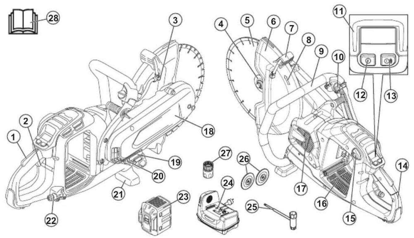
- Power trigger lockout
- Power trigger
- Water nozzle
- Flange for diamond blade, spindle, arbor bushing
- Cutting blade
- Blade guard
- Adjustment handle for blade guard
- Spindle direction of rotation
- Front handle
- Water valve
- Control panel
- On/Off button
- Accessories On/Off button (not used)
- Rear handle
- Battery release button
- Battery slot
- Motor air intake
- Belt guard
- Type plate
- Supplementary arbor bushing 20 mm/0.8 in.
- Ground support front
- Water connection with filter
- Battery (not included)
- Battery charger (not included)
- Combination wrench
- Flanges for bonded abrasive blade
- Water connector, GARDENA®
- Operator's manual
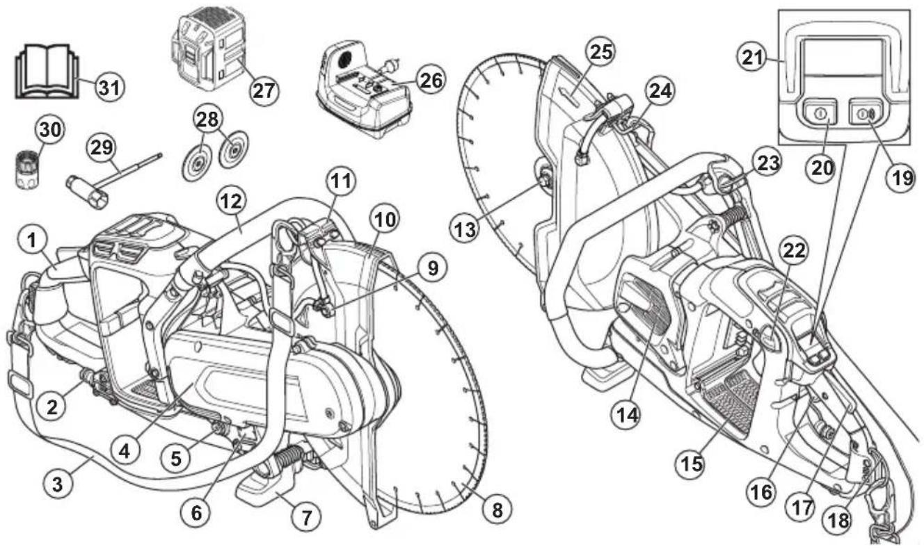
Product overview K1 PACE Rescue
-
Rear handle
-
Water connection with filter
-
Shoulder strap
-
Belt guard
-
Supplementary arbor bushing 20 mm/0.8 in.
-
Type plate
-
Ground support front
-
Cutting blade
-
Water nozzle
-
Blade guard
-
Adjustment handle for blade guard
-
Front handle
-
Flange for diamond blade, spindle, arbor bushing
-
Motor air intake
-
Battery slot
-
Power trigger
-
Power trigger lockout
-
Rear strap eyelet
-
Accessories On/Off button (not used)
-
On/Off button
-
Control panel
-
Battery release button
-
Water valve
-
Front strap eyelet
-
Spindle direction of rotation
-
Battery charger (not included)
-
Battery (not included)
-
Flanges for bonded abrasive blade
-
Combination wrench
-
Water connector, GARDENA®
-
Operator's manual
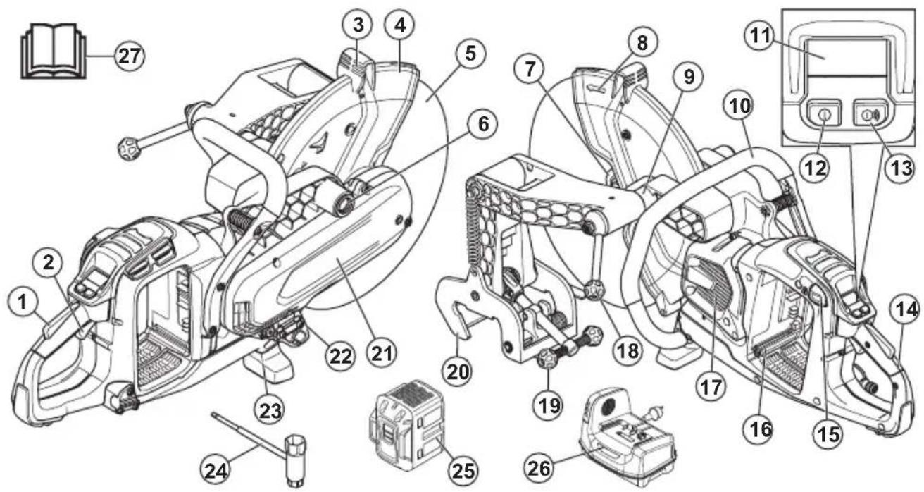
Product overview K1 PACE Rail
-
Power trigger lockout
-
Power trigger
-
Adjustment handle for blade guard
-
Blade guard
-
Cutting blade
-
Installation point for rail fixture on the right side
-
Flange for abrasive blade, spindle, arbor bushing
-
Spindle direction of rotation
-
Installation point for rail fixture on the left side
-
Front handle
-
Control panel
-
On/Off button
-
Accessories On/Off button (not used)
-
Rear handle
-
Battery release button
-
Battery slot
-
Motor air intake
-
Power cutter lock handle
-
Rail lock handle
-
Rail attachment
-
Belt guard
-
Type plate
-
Ground support front
-
Combination wrench
-
Battery (not included)
-
Battery charger (not included)
-
Operator's manual
Symbols on the product

WARNING: This product can be dangerous and cause serious injury or death to the operator or others. Be careful and use the product correctly.

Read the operator's manual carefully and make sure that you understand the instructions before you use this product.

Use approved protective helmet, hearing protection, eye protection and respiratory protection. Refer to Personal protective equipment on page 12.
Dust forms when cutting. The dust can cause injuries if inhaled. Use an approved respiratory protection. Always provide for good ventilation.
Sparks from the cutting blade can cause fire in fuel, wood, clothes, dry grass or other flammable materials.
WARNING! Kickbacks can be sudden, rapid and violent and can cause life threatening injuries. Read and understand the instructions in the manual before using the product. Refer to Kickback on page 19.

Make sure that the cutting blade does not have cracks or other damages.

Do not use circular saw blades.

Flange washers that have this symbol should only be used with dimaond blades.

This product is used for railway operations.

This product complies with applicable EU Directives.
Environmental mark. The product or package of the product is not domestic waste. Recycle it at a recycling location for electrical and electronic equipment.
Note: Other symbols/decals on the product refer to certification requirements for some markets.
Type plate
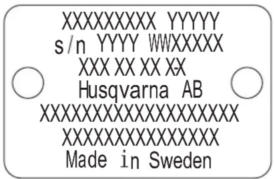
Row 1: Brand, Model
Row 2: Serial No. with manufacturing date: Year, Week, Sequence No.
Row 3: Product No.
Row 4: Manufacturer
Row 5: n=rated speed output shaft, /min=revolutions per minute, =blade diameter, spindle bolt thread.
Row 6: Maximum and nominal Voltage, d.c.=direct current
Row 7: Country of origin
Embedded connectivity
The cloud asset management solution Husqvarna Fleet Services™ gives the fleet manager an overview of all products that are connected via either embedded or aftermarket sensors. The position of the gateway or smartphone can be used to indicate the location of connected products. The sensors record data like runtime, service intervals and more. For more information about the cloud asset management solution Husqvarna Fleet Services™, download the iOS or Android app Husqvarna Fleet Services at https://apps.apple.com/se/app/husqvarna-fleet-services/id1334672726 or https://play.google.com/store/apps/details?id=com.husqvarna.hfsmobile&hl=en. Speak to your HUSQVARNA sale representative for more information.
Some types of this product are connected via the embedded Husqvarna Fleet Services ^™ sensor that has the Bluetooth Low Energy (BLE) function. For more information regarding how to use it, refer to To use embedded connectivity with Husqvarna Fleet Services ^™ on page 23. For information about the BLE technology radio spectrum, refer to Embedded connectivity on page 39.
Product damage
We are not responsible for damages to our product if:
• the product is incorrectly repaired.
- the product is repaired with parts that are not from the manufacturer or not approved by the manufacturer.
- the product has an accessory that is not from the manufacturer or not approved by the manufacturer.
- the product is not repaired at an approved service center or by an approved authority.
Safety
Safety definitions
Warnings, cautions and notes are used to point out specially important parts of the manual.

WARNING: Used if there is a risk of injury or death for the operator or bystanders if the instructions in the manual are not obeyed.

CAUTION: Used if there is a risk of damage to the product, other materials or the adjacent area if the instructions in the manual are not obeyed.
Note: Used to give more information that is necessary in a given situation.
General power tool safety warnings

WARNING: Read all safety warnings, instructions, illustrations and specifications provided with this power tool. Failure to follow all instructions listed below may result in electric shock, fire and/or serious injury.
Save all warnings and instructions for future reference. The term "power tool" in the warnings refers to your mains-operated (corded) power tool or battery-operated (cordless) power tool.
Work area safety
- Keep work area clean and well lit. Cluttered or dark areas invite accidents.
- Do not operate power tools in explosive atmospheres, such as in the presence of flammable liquids, gases or dust. Power tools create sparks which may ignite the dust or fumes.
- Keep children and bystanders away while operating a power tool. Distractions can cause you to lose control.
Electrical safety
- Power tool plugs must match the outlet. Never modify the plug in any way. Do not use any adapter plugs with earthed (grounded) power tools. Unmodified plugs and matching outlets will reduce risk of electric shock.
- Avoid body contact with earthed or grounded surfaces, such as pipes, radiators, ranges and refrigerators. There is an increased risk of electric shock if your body is earthed or grounded.
- Do not expose power tools to rain or wet conditions. Water entering a power tool will increase the risk of electric shock.
- Do not abuse the cord. Never use the cord for carrying, pulling or unplugging the power tool. Keep cord away from heat, oil, sharp edges or moving parts. Damaged or entangled cords increase the risk of electric shock.
- When operating a power tool outdoors, use an extension cord suitable for outdoor use. Use of a cord suitable for outdoor use reduces the risk of electric shock.
- If operating a power tool in a damp location is unavoidable, use a residual circuit interrupter (RCD)
protected supply. Use of a RCD reduces the risk of electric shock

WARNING: Do not pressure wash the machine, as water can enter the electrical system or the motor and cause damage to the machine or short circuit.
Personal safety
- Stay alert, watch what you are doing and use common sense when operating a power tool. Do not use a power tool while you are tired or under the influence of drugs, alcohol or medication. A moment of inattention while operating power tools may result in serious personal injury.
- Use personal protective equipment. Always wear eye protection. Protective equipment such as dust mask, non-skid safety shoes, hard hat, or hearing protection used for appropriate conditions will reduce personal injuries.
- Prevent unintentional starting. Ensure the switch is in the OFF-position before connecting to a power source and/or battery pack, picking up or carrying the tool. Carrying power tools with your finger on the switch or energizing power tools that have the switch on invites accidents.
- Remove any adjusting key or wrench before turning the power tool on. A wrench or a key left attached to a rotating part of the power tool may result in personal injury.
- Do not overreach. Keep proper footing and balance at all times. This enables better control of the power tool in unexpected situations.
- Dress properly. Do not wear loose clothing or jewellery. Keep your hair, clothing and gloves away from moving parts. Loose clothes, jewellery or long hair can be caught in moving parts.
- If devices are provided for the connection of dust extraction and collection facilities, ensure these are connected and properly used. Use of dust collection can reduce dust-related hazards.
- Do not let familiarity gained from frequent use of tools allow you to become complacent and ignore tool safety principles. A careless action can cause severe injury within a fraction of a second.
- The vibration emission during actual use of the power tool can differ from the declared total value depending on the ways in which the tool is used. Operators should identify safety measures to protect themselves that are based on an estimation of exposure in the actual conditions of use (taking account of all parts of the operating cycle such as the times when the tool is switched off and when it is running idle in addition to the trigger).
- Remain at a distance from the blade when the motor is running.
Power tool use and care
- Do not force the power tool. Use the correct power tool for your application. The correct power tool will do the job better and safer at the rate for which it was designed.
- Do not use the power tool if the switch does not turn it on and off. Any power tool that cannot be controlled with the switch is dangerous and must be repaired.
- Disconnect the plug from the power source and/or the battery pack from the power tool before making any adjustments, changing accessories, or storing power tools. Such preventive safety measures reduce the risk of starting the power tool accidentally.
- Store idle power tools out of the reach of children and do not allow persons unfamiliar with the power tool or these instructions to operate the power tool. Power tools are dangerous in the hands of untrained users.
- Maintain power tools. Check for misalignment or binding of moving parts, breakage of parts and any other condition that may affect the power tool's operation. If damaged, have the power tool repaired before use. Many accidents are caused by poorly maintained power tools.
- Keep cutting tools sharp and clean. Properly maintained cutting tools with sharp cutting edges are less likely to bind and are easier to control.
- Use the power tool, accessories and tool bits etc. in accordance with these instructions, taking into account the working conditions and the work to be performed. Use of the power tool for operations different from those intended could result in a hazardous situation.
- Keep handles and grasping surfaces dry, clean and free from oil and grease. Slippery handles and grasping surfaces do not allow for safe handling and control of the tool in unexpected situations.
- Under no circumstances should you modify the original design of the machine without approval from the manufacturer. Always use original spare parts. Unauthorized modifications and/or accessories may lead to serious injury or death to the user or others.
- Make sure that no pipes or electrical cables are routed in the working area or in the material to be cut.
• Always check and mark out where gas pipes are routed. Cutting close to gas pipes always entails danger. Make sure that sparks are not caused when cutting in view of the risk of explosion. Remain concentrated and focused on the task. Carelessness can result in serious personal injury or death.
Battery tool use and care
- Recharge only with the charger specified by the manufacturer. A charger that is suitable for one type of battery pack may create a risk of fire when used with another battery pack.
- Use power tools only with specifically designated battery packs. Use of any other battery packs may create a risk of injury and fire.
- When battery pack is not in use, keep it away from other metal objects, like paper clips, coins, keys, nails, screws or other small metal objects, that can make a connection from one terminal to another. Shorting the battery terminals together may cause burns or a fire.
- Under abusive conditions, liquid may be ejected from the battery; avoid contact. If contact accidentally occurs, flush with water. If liquid contacts eyes, additionally seek medical help. Liquid ejected from the battery may cause irritations or burns.
- Do not use a battery pack or tool that is damaged or modified. Damaged or modified batteries may exhibit unpredictable behaviour resulting in fire, explosion or risk of injury.
- Do not expose a battery pack or tool to fire or excessive temperature. Exposure to fire or temperature above 130^ / 265^ may cause explosion.
- Follow all charging instructions and do not charge the battery pack or tool outside the temperature range specified in the instructions. Charging improperly or at temperatures outside the specified range may damage the battery and increase the risk of fire.
Service
- Have your power tool serviced by a qualified repair person using only identical replacement parts. This will ensure that the safety of the power tool is maintained.
- Never service damaged battery packs. Service of battery packs should only be performed by the manufacturer or authorized service providers.
Cut-off machine safety warning
- The guard provided with the tool must be securely attached to the power tool and positioned for maximum safety so the least amount of wheel is exposed towards the operator. Position yourself and bystanders away from the plane of the rotating wheel. The guard helps to protect operator from broken wheel fragments and accidental contact with the wheel.
- Use only bonded reinforced or diamond cut-off wheels for your power tool. Just because an accessory can be attached to your power tool, it does not assure safe operation.
- The rated speed of the accessory must be at least equal to the maximum speed marked on the power tool. Accessories running faster than their rated speed can break and fly apart.
- Wheels must be used only for recommended applications. For example, do not grind with the side of the cut-off wheel. Abrasive cut-off wheels are
intended for peripheral grinding, side forces applied to these wheels may cause them to shatter.
- Always use undamaged wheel flanges that are of correct diameter for your selected wheel. Proper wheel flanges support the wheel thus reducing the possibility of wheel breakage.
- Do not use worn down reinforced wheels from larger power tools. Wheels intended for a larger power tool are not suitable for the higher speed of a smaller tool and may burst.
- The outside diameter and the thickness of your accessory must be within the capacity rating of your power tool. Incorrectly sized accessories cannot be adequately guarded or controlled.
- The arbour size of wheels and flanges must properly fit the spindle of the power tool. Wheels and flanges with arbour holes that do not match the mounting hardware of the power tool will run out of balance, vibrate excessively and may cause loss of control.
- Do not use damaged wheels. Before each use, inspect wheels for chips and cracks. If power tool or wheel is dropped, inspect for damage or install an undamaged wheel. After inspecting and installing the wheel, position yourself and bystanders away from the plane of the rotating wheel and run the power tool at maximum no load speed for one minute. Damaged wheels will normally break apart during this test time.
- Wear personal protective equipment. Depending on application, use face shield, safety goggles or safety glasses. As appropriate, wear dust mask, hearing protectors, gloves and shop apron capable of stopping small workpiece fragments. The eye protection must be capable of stopping flying debris generated by various operations. The dust mask or respirator must be capable of filtrating particles generated by your operation. Prolonged exposure to high intensity noise may cause hearing loss.
- Keep bystanders a safe distance away from work area. Anyone entering the work area must wear personal protective equipment. Fragments of workpiece or a broken wheel may fly away and cause injury beyond immediate area of operation.
- Hold the power tool by insulated gripping surfaces only, when performing an operation where the cutting accessory may contact hidden wiring. Cutting accessory contacting a "live" wire may make exposed metal parts of the power tool "live" and could give the operator an electric shock.
- Position the cord clear of the spinning accessory. If you lose control, the cord may be cut or snagged and your hand or arm may be pulled into the spinning wheel.
- Never lay the power tool down until the accessory has come to a complete stop. The spinning wheel may grab the surface and pull the power tool out of your control.
- Do not run the power tool while carrying it at your side. Accidental contact with the spinning accessory
could snag your clothing, pulling the accessory into your body.
- Regularly clean the power tool's air vents. The motor's fan will draw the dust inside the housing and excessive accumulation of powdered metal may cause electrical hazards.
- Do not operate the power tool near flammable materials. Sparks could ignite these materials.
Kickback and related warnings
- Kickback is a sudden reaction to a pinched or snagged rotating wheel. Pinching or snagging causes rapid stalling of the rotating wheel which in turn causes the uncontrolled power tool to be forced in the direction opposite of the wheel's rotation at the point of the binding.
- For example, if an abrasive wheel is snagged or pinched by the workpiece, the edge of the wheel that is entering into the pinch point can dig into the surface of the material causing the wheel to climb out or kick out. The wheel may either jump toward or away from the operator, depending on direction of the wheel's movement at the point of pinching. Abrasive wheels may also break under these conditions.
- Kickback is the result of power tool misuse and/or incorrect operating procedures or conditions and can be avoided by taking proper precautions as given below.
- Maintain a firm grip on the power tool and position your body and arm to allow you to resist kickback forces. Always use auxiliary handle, if provided, for maximum control over kickback or torque reaction during start-up. The operator can control torque reactions or kickback forces, if proper precautions are taken.
- Never place your hand near the rotating accessory. Accessory may kickback over your hand.
- Do not position your body in line with the rotating wheel. Kickback will propel the tool in direction opposite to the wheel's movement at the point of snagging.
- Use special care when working corners, sharp edges etc. Avoid bouncing and snagging the accessory. Corners, sharp edges or bouncing have a tendency to snag the rotating accessory and cause loss of control or kickback.
- Do not attach a saw chain, woodcarving blade, segmented diamond wheel with a peripheral gap greater than 10 mm or toothed saw blade. Such blades create frequent kickback and loss of control.
- Do not "jam" the wheel or apply excessive pressure. Do not attempt to make an excessive depth of cut. Overstressing the wheel increases the loading and susceptibility to twisting or binding of the wheel in the cut and the possibility of kickback or wheel breakage.
- When wheel is binding or when interrupting a cut for any reason, switch off the power tool and hold
the power tool motionless until the wheel comes to a complete stop. Never attempt to remove the wheel from the cut while the wheel is in motion otherwise kickback may occur. Investigate and take corrective action to eliminate the cause of wheel binding.
- Do not restart the cutting operation in the workpiece. Let the wheel reach full speed and carefully re-enter the cut. The wheel may bind, walk up or kickback if the power tool is restarted in the workpiece.
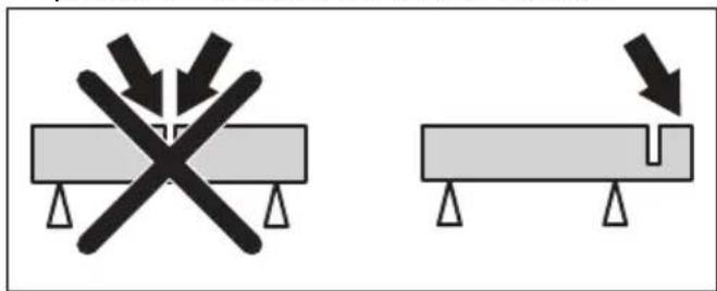
- Support panels or any oversized workpiece to minimize the risk of wheel pinching and kickback. Large workpieces tend to sag under their own weight. Supports must be placed under the workpiece near the line of cut and near the edge of the workpiece on both sides of the wheel.
- Use extra caution when making a “pocket cut” into existing walls or other blind areas. The protruding wheel may cut gas or water pipes, electrical wiring or objects that can cause kickback.
General safety instructions

WARNING: Read the warning instructions that follow before you use the product.
- A power cutter is a dangerous tool if used carelessly or incorrectly and can cause serious injury or death. It is very important that you read and understand the contents of this operator's manual. It is also recommended that first time operators also obtain practical instruction before using the product.
- Do not do modifications to this product. Modifications that are not approved by the manufacturer, can cause serious injury or death.
- Do not operate the product if it is possible that other persons have done modifications to the product.
• Always use original accessories and spare parts. Accessories and spare parts that are not approved by the manufacturer, can cause serious injury or death. - Keep the product clean. Make sure that you can clearly read signs and decals.
- Never allow children or other persons not trained in the use of the product to use or service it.
- Do not let a person operate the product unless they read and understand the contents of the operator's manual.
- Only let approved persons operate the product.
- The safety distance for the power cutter is 15 m/50 ft. Make sure that animals and bystanders are not in the work area.
- This product produces an electromagnetic field during operation. This field can under some circumstances interfere with active or passive medical implants. To decrease the risk of serious injury or death, we recommend persons with medical implants to speak to their physician and the medical implant manufacturer before operating this product.
- The information in this operator's manual is never a substitute for professional skills and experience. If you are in a situation where you feel unsafe, stop and get expert advice. Speak to your servicing dealer. Do not try any task that you feel unsure of.
Battery safety

WARNING: Read the warning instructions that follow before you use the product.

WARNING: A damaged battery can cause an explosion and cause injury. If the battery has a deformation or is damaged, speak to an approved HUSQVARNA service agent.
- Only use the Husqvarna PACE batteries that we recommend for your product. The batteries are software encrypted.
- Use only original batteries for this product. There is a risk of explosion if the batteries are replaced with a battery of incorrect type. Speak to your dealer for more information.
- Use Husqvarna PACE batteries that are rechargeable as a power supply for the related HUSQVARNA products only. To prevent injury, do not use the battery as a power supply for other devices.
- Risk of electrical shock. Do not connect the battery terminals to keys, screws or other metal. This can cause a short circuit of the battery.
- If the battery leaks, do not let the liquid touch your body, clothes or the product. If you touch the liquid, clean the area with a large quantity of water and get medical aid.
- Use protective glasses when you are near batteries. If you get liquid in your eyes, do not rub but flush with water for a minimum of 15 minutes. Get medical aid.
- Do not use batteries that are non-rechargeable.
- Do not do modifications to the battery.
- Do not put objects into the air slots of the battery.
- Keep the battery away from sunlight, heat or open flame. The battery can cause an explosion and cause burns and/or chemical burns.
- Keep the battery away from rain and wet conditions.
- Keep the battery away from microwaves and high pressure.
- Do not try to disassemble or break the battery.
- Use the battery only when the ambient temperature is between -10^ / 14^ and 40^ / 104^ .
- Do not clean the battery or the battery charger with water. Refer to To clean the battery and the battery charger on page 33.
- Do not use a damaged battery.
-
Keep batteries in storage away from metal objects such as nails, screws or jewelry.
-
Keep the battery away from children.
- Attach the battery correctly. An incorrectly attached battery can cause a short circuit of the battery.
Battery charger safety

WARNING: Read all safety warnings and all instructions. Failure to follow the warnings and instructions may result in electrical shock, fire and/or serious injury.
- Risk of electrical shock or short circuit if the safety instructions are not obeyed.
- Do not use other battery chargers than the one supplied for your product. Only use HUSQVARNA QC chargers to charge HUSQVARNA replacement batteries.
- Do not try to disassemble the battery charger.
- Do not use a damaged battery charger or a battery charger that does not operate correctly.
- Do not lift the battery charger by the power cord. To disconnect the battery charger from a mains socket, pull out the plug. Do not pull the power cord.
- Keep all cables and extension leads away from water, oil and sharp edges. Make sure that the cable is not caught between doors, fences or equivalent.
- Do not use the battery charger near flammable materials or materials that can cause corrosion. Make sure that the battery charger is not covered. Pull out the plug to the battery charger if there is smoke or fire.
- Only charge the battery indoors in a location with good airflow and away from sunlight. Do not charge the battery outdoors. Do not charge the battery in wet conditions.
- Only charge the battery when the ambient temperature is between 5^ / 41^ and 40^ / 104^ . Use the charger in an environment which has a good airflow, is dry and free from dust.
- Do not put objects into the air slots of the battery charger.
- Do not connect the battery charger terminals to metal objects as this can short circuit the battery charger.
- Do not charge non-rechargeable batteries in the battery charger or use them in the machine.
- Use approved mains sockets that are not damaged.
Safety instructions for operation

WARNING: Read all safety warnings and all instructions. Failure to follow the warnings and instructions may result in electrical shock, fire and/or serious injury.
- Do not cut asbestos materials.
- When dry cutting, make sure the dust is removed safely.
- The information in this manual is not a replacement for professional knowledge and experience. If you do not feel safe in the situation that you are in, stop the product. Do not use the product in unknown situations.
- Turn to your servicing dealer or HUSQVARNA if you have questions about the operation of the product. We can give you information about how to operate your product safely with best result.
- Do not use a product, battery or battery charger that is damaged or does not operate correctly.
- Do not touch a rotating cutting blade. It can cause serious injuries or death.
- Do not use the product in bad weather, for example, heavy fog or rain, strong wind and intense cold. Bad weather add risks such as ice on the ground.
- Do not start a product unless all covers and guards are assembled correctly.
- Look around you. Make sure that there is no risk that persons or animals touch or influence on your control of the product.
- Do not let children use or be near the product. The product is easy to start. This can mean a risk of serious injury.
- Remove the battery when you do not have full view of the product. Remove the battery if you will not use the product for a long time.
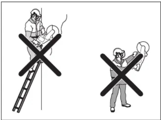
- You must be stable on your feet in order to have full control of the product. Do not use the product if you are on a ladder. Do not use the product if you are not on stable ground.
- Do not use the product above shoulder height.
- If you are not careful, the risk of kickback increases.
- Do not hold the product with one hand. This product is not safely controlled with one hand.
- Do not use a product in a situation where you can not get for support if an accident occurs.
- Make sure that you can move around safely.
Examine the conditions and the terrain around you for possible obstacles.
• Overexposure to vibration can lead to circulatory damage or nerve damage in people who have impaired circulation. Contact your doctor if you experience symptoms of overexposure to vibration. Such symptoms include numbness, loss of feeling, tingling, pricking, pain, loss of strength, changes in skin colour or condition. These symptoms normally appear in the fingers, hands or wrists. These symptoms may be increased in cold temperatures. - It is not possible to include each possible situation you can face when you use this product. Always be careful and use your common sense.
Note: After operating the tool, hearing protection must be lifted immediately when sawing is completed to hear sounds and warning signals can be heard.
Personal protective equipment

WARNING: Read the warning instructions that follow before you use the product.
• Always use approved personal protective equipment during operation. Personal protective equipment cannot eliminate the risk of injury but it will reduce the degree of injury if an accident does happen. Ask your servicing dealer for help in choosing the right equipment.
- Use an approved protective helmet.
- Use approved hearing protection. Long-term exposure to noise can result in permanent hearing impairment. Be aware of warning signals or shouts when you are wearing hearing protection. Always
remove your hearing protection as soon as the motor stops.
- Use approved eye protection to decrease the risk of injury from thrown objects. If you use a face shield then you must also wear approved protective goggles. Approved protective goggles must comply with standard ANSI Z87.1 in the USA or EN 166 in EU countries. Visors must comply with standard EN 1731.
- Use heavy duty gloves.
- Use approved respiratory protection. The use of products such as cutters, grinders, drills, that sand or form material can generate dust and vapours which may contain hazardous chemicals. Check the nature of the material you intend to process and use appropriate breathing mask.
- Use tight-fitting, heavy-duty and comfortable clothing that permits full freedom of movement. Cutting generates sparks that can ignite clothing. HUSQVARNA recommends that you wear flame-retardant cotton or heavy denim. Do not wear clothing made of material such as nylon, polyester or rayon. If ignited such material can melt and cling to the skin. Do not wear shorts.
- Use boots with steel toe-cap and non-slip sole.
• Always keep a first aid kit near.

natural_image
Illustration of a person wearing full-body protective gear and a first aid kit (no text or symbols)- Sparks can come from the cutting blade. Always have a fire extinguishing available.
Safety devices on the product

WARNING: Read the warning instructions that follow before you use the product.
- Do not use a product with safety devices that are damaged or do not operate correctly.
- Do a check of the safety devices regularly. If the safety devices are damaged or do not operate correctly, speak to your HUSQVARNA approved service agent.
- Do not change the safety devices.
- Do not use the product if protective plates, protective covers, safety switches or other protective devices are damaged or not attached.
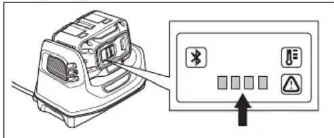
Functions of the control panel
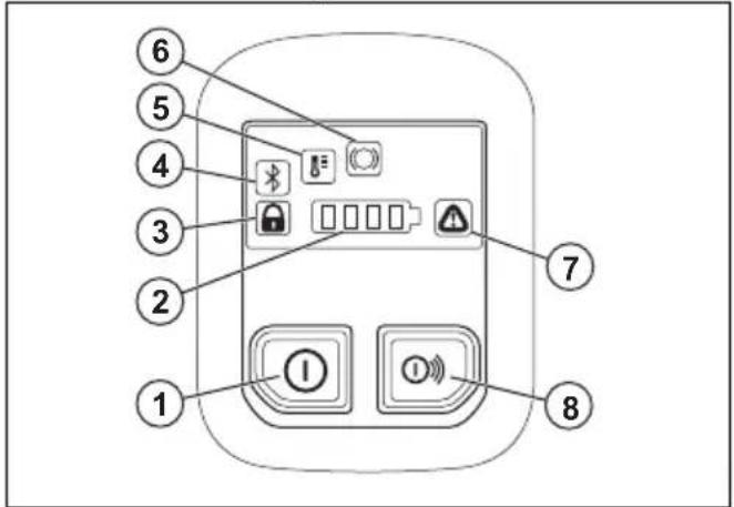
- On/Off button.
- Battery status indicator.
- Rail fixture indicator, engaged or disengaged. Only for K1 PACE Rail. Refer to Troubleshooting of the product on page 35.
- Bluetooth ^® . Refer to Bluetooth ^® wireless technology on page 23.
- Temperature warning indicator, high or low. Refer to Troubleshooting of the product on page 35
- X-Halt warning. Refer to Troubleshooting of the product on page 35 and X-Halt on page 13
- Error/Warning indicator. Refer to Troubleshooting of the product on page 35.
- Accessories On/Off button (not used).
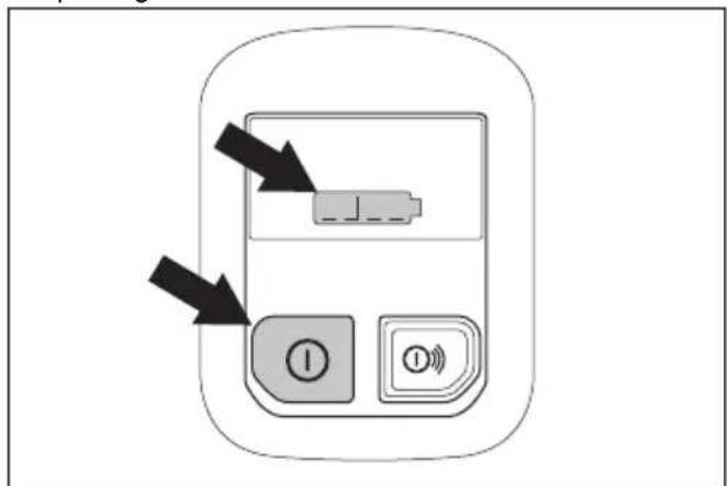
To do a check of the control panel
-
Push and hold the On/Off button until the battery status indicator comes on. Refer to To start the product on page 26.
-
Push and hold the On/Off button until the control panel goes off.
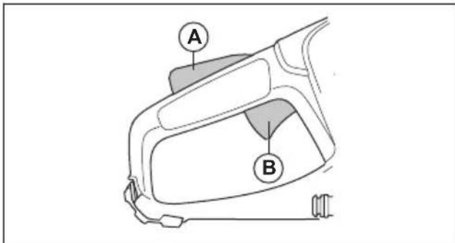
Power trigger lockout
The power trigger lockout prevents accidental operation of the power trigger. If you put your hand around the handle and press the power trigger lockout (A), it releases the power trigger (B). If you release the handle, the power trigger and the power trigger lockout move back to their initial positions.
Automatic stop function
The automatic stop function stops the product and makes the control panel go off if you do not use it for 3 minutes.
X-Halt
The X-Halt function is an electronic brake system that is engaged if a kickback occurs. The function can not fully prevent personal injury from a kickback, but it decreases the risk. A safe working technique is necessary to prevent kickbacks and to decrease the risk of injuries.
The X-Halt function is always on when the product is on. If the function is engaged, the control panel shows the X-Halt waning symbol until the product becomes cool. Refer to Functions of the control panel on page 13. For more information, refer to Troubleshooting of the product on page 35.
Blade guard

WARNING: Make sure that the blade guard is correctly attached before you start the product. Do not use the product if the blade guard is missing, has cracks or other damage.
The blade guard is installed above the cutting blade. The blade guard prevents injury if parts of the blade or pieces from the cut material are thrown in the direction of the operator.
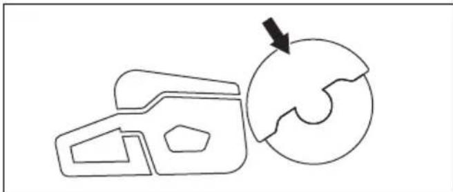
natural_image
Simple line drawing of a 3D object with an arrow pointing to a circular shape (no text or symbols)To examine the blade and the blade guard

WARNING: A damaged cutting blade can cause injury.
- Make sure that the cutting blade is attached correctly and does not show signs of damage.
- Make sure that the blade guard has no cracks or is damaged.
- Replace the blade guard if it is damaged.
Vibration damping system
Your product is equipped with a vibration damping system that is designed to minimize vibration and make operation easier. The product's vibration damping system reduces the transfer of vibration between the motor unit/cutting equipment and the product's handle unit.
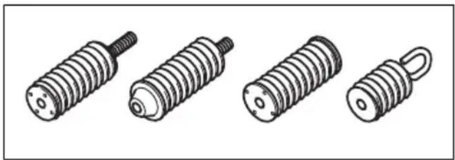
natural_image
Illustration of four different types of screwdrivers, shown in line drawings without any text or symbols.To do a check of the vibration damping system

WARNING: Make sure that the motor is off and that the battery is disconnected.
- Make sure that there are no cracks or deformation on the vibration damping units. Replace the vibration damping units if they are damaged.
- Make sure that the vibration damping units are correctly attached to the motor unit and handle unit.
Vibration safety

WARNING: Read the warning instructions that follow before you use the product.
- During operation of the product, vibrations go from the product to the operator. Regular and frequent operation of the product can cause or increase the degree of injuries to the operator. Injuries can occur in fingers, hands, wrists, arms, shoulders, and/or nerves and blood supply or other body parts. The injuries can be debilitating and/or permanent, and can increase gradually during weeks, months or years. Possible injuries include damage to the blood circulation system, the nervous system, joints, and other body structures.
-
Symptoms can occur during operation of the product or at other times. If you have symptoms and continue to operate the product, the symptoms can increase or become permanent. If these or other symptoms occur, get medical aid:
-
Numbness, loss of feeling, tingling, pricking, pain, burning, throbbing, stiffness, clumsiness, loss of strength, changes in skin color or condition.
- Symptoms can increase in cold temperatures. Use warm clothing and keep your hands warm and dry when you operate the product in cold environments.
- Do maintenance on and operate the product as given in the operator's manual, to keep a correct vibration level.
- Let the product do the work. Do not push the product with force. Hold the product at the handles lightly, but make sure that you control the product and operate it safely.
- Keep your hands on the handles only. Keep all other body parts away from the product.
- Stop the product immediately if strong vibrations suddenly occurs. Do not continue the operation before the cause of the increased vibrations is removed.
- To cut granite or hard concrete causes more vibration in the product than if you cut soft concrete. Cutting equipment that is blunt, damaged, of incorrect type or incorrectly sharpened, increases the vibration level
Safety instructions for maintenance

WARNING: Read the warning instructions that follow before you do maintenance on the product.
- Remove the battery before you do maintenance, other checks or assemble the product.
- The operator must only do the maintenance and servicing shown in this operator's manual. Turn to your servicing dealer for maintenance and servicing of a larger extension.
- Do not clean the battery or the battery charger with water. Strong detergent can cause damage to the plastic.
- If you do not do maintenance, it decreases the life cycle of the product and increases the risk of accidents.
- Special training is necessary for all servicing and repair work, especially for the safety devices on the product. If not all checks in this operator's manual are approved after you have done maintenance, turn to your servicing dealer. We guarantee that there are professional repairs and servicing available for your product.
- Only use original spare parts.
Assembly
Cutting blades

WARNING: Always use protective gloves when you assemble the product.

WARNING: A cutting blade can break and cause injury to the operator.

WARNING: Examine the cutting blade for cracks, lost segments distortion or unbalance prior to use and immediately after striking an unintended object. Do not use a damaged cutting blade. After inspecting and installing the cutting blade, position yourself and bystanders away from the plane of the rotating cutting blade and run the power tool at maximum no load speed for one minute.

WARNING: The cutting blade manufacturer gives warnings and recommendations for the operation and correct maintenance of the cutting blade. Those warnings are supplied with the cutting blade. Read and obey the instructions that are supplied with the cutting blade.
Cutting blade vibration

CAUTION: If you use the product with too much force, the cutting blade can become too hot, bend and cause vibrations. Use the product with less force. If the vibrations continue, replace the cutting blade.
Applicable cutting blades

CAUTION: Use HUSQVARNA recommended cutting blades for K1 PACE and the material to be cut. The recommended cutting blades decrease the risk of serious injury and increase the cutting and X-halt performance. If general high speed cutting blades are used, the performance and cutting quality will decrease.

WARNING: Only use diamond blades and abrasive blades for concrete and metal. Do not use blades with serrations such as circular wood cutting blades or blades
with carbide tips. The risk of kickback is increased and carbide tips can come off and be thrown at high speed. This can result in injury or death.

WARNING: Never use a cutting blade for any other materials than what it was intended to cut.

WARNING: Use only cutting blades that comply with applicable national or regional standards, for example EN12413, ANSI B7.1. or EN13236.

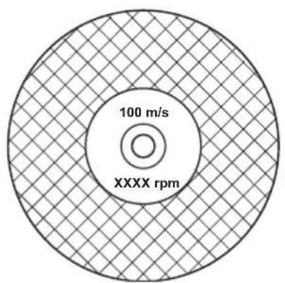
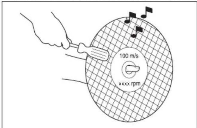
WARNING: Do not use a cutting blade with a rated speed value lower than that of the product. The rated speed value of the cutting blade is marked on the cutting blade and that of the product is marked on the type plate.
pie
| Category | Value | |---|---| | 100 m/s (inner ring) | 100 | | XXXX rpm (outer ring) | 100 |Note: Many cutting blades that can be attached to this product are made for stationary saws. The rated speed value of those cutting blades is too low for this product.

WARNING: Do not use cutting blades with thickness exceeding maximum recommended thickness. Refer to Technical data on page 38.
- Cutting blades applicable to this product are available in two basic models; bonded abrasive blades and diamond blades.
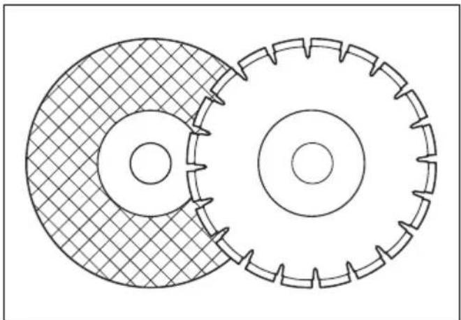
natural_image
Technical line drawing of two interlocking gears with no text or symbols• Make sure that the cutting blade has the correct center hole dimension for the installed arbor bushing.
Abrasive blades

WARNING: Do not use abrasive blades with water. Water or moisture decreases the strength of the abrasive blade and increases the risk that the blade breaks.

CAUTION: Cutting with abrasive blade is not permitted with the Vac attachment. Use of abrasive blade causes too much wear on the Vac attachment.

WARNING: Use correct abrasive blade on correct material.
- Do not use wheels from larger power tools. Wheels of a larger power tool are not correct for the higher speed of a smaller tool and may break.
- The cutting material on abrasive blades is bonded with natural material that have a gravel bonded agent. Blades that are made up of a fabric or fibre are stronger. This type of blade does not break if the blade gets cracks or becomes damaged during operation.
- The performance of a cutting blade is given by the dimension of abrasive grain, and the type and hardness of the bonding agent.
Bonded abrasive cutting blades for different materials
Note: Make sure that you use the correct cutting blades for rail cutting.
| Blade type Material | |
| Stone Concrete blade | Concrete, asphalt, stone masonry, cast iron, aluminum, copper, brass, cables, rubber and plastic. |
| Steel blade Steel | alloy steel and other hard metal. |
| Rail blade Railway rail. | |
To examine a bonded abrasive cutting blade
- Make sure that there are no cracks or damages on the cutting blade.
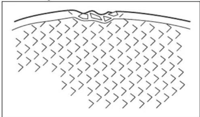
natural_image
Diagram of a geological cross-section showing layered strata with no text or symbols- Hang the cutting blade on your finger and hit the cutting blade lightly with a screwdriver. If you do not hear a clear sound, the cutting blade is damaged.
Diamond blades

WARNING: Diamond blades become very hot when used. A diamond blade that is too hot gives bad performance, blade damage and is a safety risk.

WARNING: Do not use diamond blades to cut plastic material. The hot diamond blade can melt the plastic, which can cause a kickback.
- Diamond blades have a steel core with segments that are made of industrial diamonds.
- Diamond blades are used for masonry, reinforced concrete and stone.
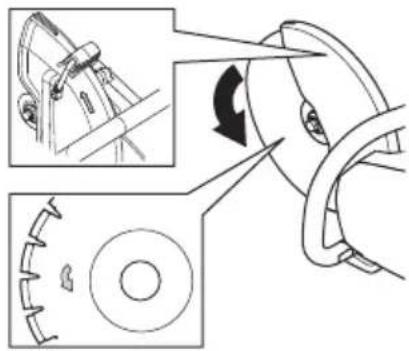
- Make sure that the diamond blade rotates in the direction of the arrows shown on the diamond blade.
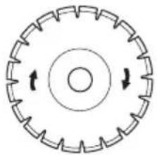
natural_image
Circular mechanical component with evenly spaced teeth and central bore, no text or symbols present• Always use a sharp diamond blade.
- Diamond blades can become blunt if you use an incorrect feeding pressure or when you cut materials such as hard reinforced concrete. If you use a blunt diamond blade it becomes too hot, which can cause the diamond segments to come loose.
To sharpen the cutting blade
Note: For the best cutting results, use a sharp cutting blade.
• To sharpen the cutting blade, cut into soft material, such as sandstone or brick.
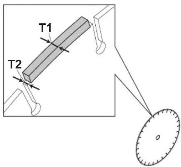
Diamond blade - requirements

WARNING: Make sure the diamond segment (T1) is wider than the blade (T2). This is to prevent pinching in the cutting slot and a kickback.

WARNING: Do not use diamond blades with positive rake angles.

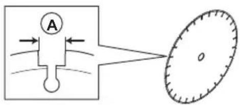
WARNING: Do not use diamond blades with greater gap between segments than max 10 mm (A).

WARNING: Do not use diamond blades with greater blade thickness than recommended maximum, refer to Technical data on page 38.

WARNING: Some cutting situations and worn blades may cause increased wear on the side of the segments. Replace the blade before it is worn out.
Diamond blades for wet cutting

WARNING: Always use a blade flange dimension that is specified for the current blade dimension. Do not use blade flanges that are damaged.
During the operation, the friction causes the diamond blade to become very hot. If the diamond blade becomes too hot, it will decrease the blade tension or make the core crack.
Let the diamond blade become cool before you touch it.
- Diamond blades for wet cutting must be used with water to keep the diamond blade core and segments cool during cutting. Diamond blades for wet cutting can not be used dry.
- If you use diamond blades for wet cutting without water, the diamond blade can become too hot. This
gives bad performance, blade damage and is a safety risk.
Diamond blades for dry cutting
- For diamond blades for dry cutting it is necessary to have a sufficient airflow around the cutting blade to decrease the temperature. Because of this, diamond blades for dry cutting are recommended only for intermittent operation. After some seconds of operation, it is necessary to let the diamond blade rotate freely, away from the cut. This lets the airflow around the blade decrease the temperature of the diamond blade.
Toothed blades

WARNING: Never use toothed blades such as wood cutting blades, circular toothed blades, carbide tipped blades, etc. The risk of kickback is significantly increased and tips can be torn off and thrown at high speed. Carelessness can result in serious personal injury or even death.

WARNING: Government regulation requires a different type of guarding for carbide tipped blades not available on power cutters – a 360 degree guard. Power Cutters (this saw) use diamond blades and have a different guarding system which does not provide protection against the dangers presented by wood cutting blades.
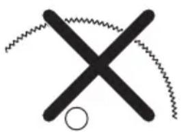
natural_image
Simple black cross-shaped line drawing with zigzag lines and a circle at the bottom (no text or symbols)Use of this power cutter with a carbide tipped blade is a violation of work safety regulations.
Due to the hazardous nature and exigent circumstances involved with fire fighting and rescue operations conducted by the various highly trained public safety forces, safety professionals (fire departments), Husqvarna is aware that they may use this power cutter with carbide tipped blades in certain emergency situations due to the ability of carbide tipped blades to cut many different types of obstructions and materials in combination without having to take time to switch blades or machines. When using this power cutter be aware at all times that carbide tipped blades are more kickback prone than diamond blades if not used properly. Carbide tipped blades can also throw pieces of material away from the blade.
For these reasons, a power cutter equipped with a carbide tipped blade should never be used except by highly trained public safety professionals who are aware of the risks associated with its use and then only in those exigent circumstances when other tools are deemed inefficient and ineffective for fire or rescue operations. A power cutter equipped with a carbide tipped blade should never be used to cut wood in non-rescue operations.
To examine the spindle shaft and the flange washers

WARNING: Use only HUSQVARNA flange washers. For minimum diameter of flange washer refer to Technical data on page 38.

WARNING: The small flange washers with a diamond blade symbol must only be used with diamond blades. Incorrect flange washers used on an bonded abrasive blade increases the risk of blade failure and injuries.

WARNING: Do not use damaged, worn or dirty flange washers. Use only flange washers of the same dimension. Incorrect flange washers can cause the cutting blade to become damaged or come loose.
Examine the spindle shaft and the flange washers when you replace the cutting blade.
- Make sure that the threads on the spindle shaft are not damaged. Replace damaged parts.
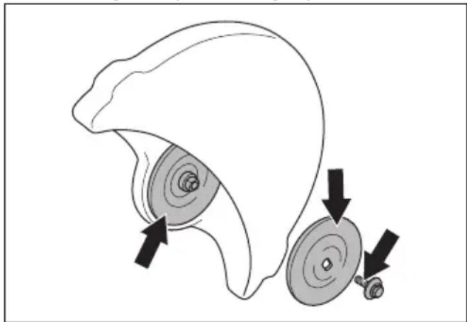
natural_image
Diagram of a mechanical component with two circular parts and directional arrows indicating motion (no text or symbols)-
Make sure that the areas of contact on the cutting blade and the flange washers are not damaged. Replace damaged parts.
-
Make sure that the flange washers are clean and of the correct dimension.
-
Make sure that the flange washers move freely on the spindle shaft.
To install the cutting blade

WARNING: Make sure that the motor is off and that the battery is disconnected.

WARNING: Always use protective gloves when you assemble the product.
- Examine the flange washers and the spindle shaft. Refer to To examine the spindle shaft and the flange washers on page 18.
- Put the cutting blade on the arbor bushing (A) between the inner flange washer (B) and the flange washer (C). Turn the flange washer until it holds on to the shaft.
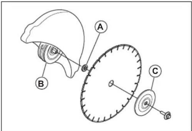
- Put a tool into the hole in the belt guard and turn the cutting blade until the shaft is locked.
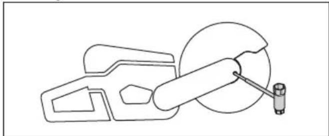
natural_image
Technical line drawing of a mechanical assembly with no visible text or symbols- Tighten the cutting blade bolt to 30 Nm/18.5 ft-lb.
Strap eyelet (K1 PACE Rescue)
The product has 2 strap eyelets. The eyelets are used to attach the shoulder strap.
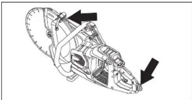
natural_image
Technical line drawing of a mechanical assembly with two arrows indicating directional components (no text or symbols present)Operation
Introduction

WARNING: Read and understand the safety chapter before you use the product.
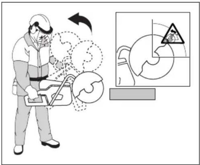
Kickback

WARNING: Kickbacks are sudden and can be very violent. The power cutter can be thrown up and back towards the user in a rotating motion causing serious or even fatal injury. It is vital to understand what causes kickback and how to avoid it before using the product.
Kickback is the sudden upward motion that can occur if the blade is pinched or stalled in the kickback zone. Most kickbacks are small and pose little danger. However a kickback can also be very violent and throw the power cutter up and back towards the user in a rotating motion causing serious or even fatal injury.
Reactive force
A reactive force is always present when cutting. The force pulls the product in the opposite direction to the blade rotation. Most of the time this force is insignificant. If the blade is pinched or stalled, the reactive force will be strong and you might not be able to control the power cutter.
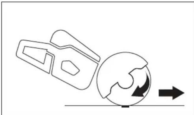
natural_image
Diagram showing a mechanical component interacting with a globe and directional arrow (no text or symbols)Never move the product when the cutting equipment is rotating. Gyroscopic forces can obstruct the intended movement
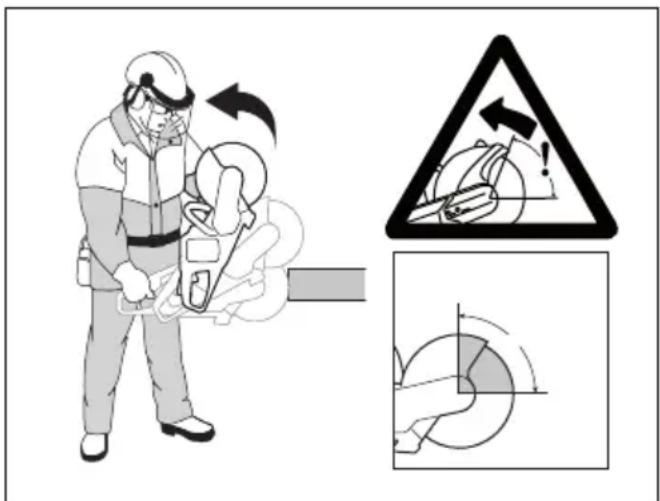
Kickback zone
Never use the kickback zone of the blade for cutting. If the blade is pinched or stalled in the kickback zone, the reactive force will push the power cutter up and back towards the user in a rotating motion causing serious or even fatal injury.
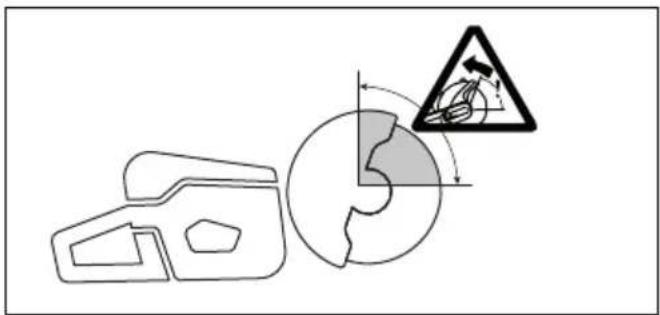
Rotational kickback
A rotational kickback occurs when the cutting blade does not move freely in the kickback zone.
Climbing kickback
If the kickback zone is used for cutting, the reactive force drives the blade to climb up in the cut. Do not use the kickback zone. Use the lower quadrant of the blade to avoid climbing kickback.
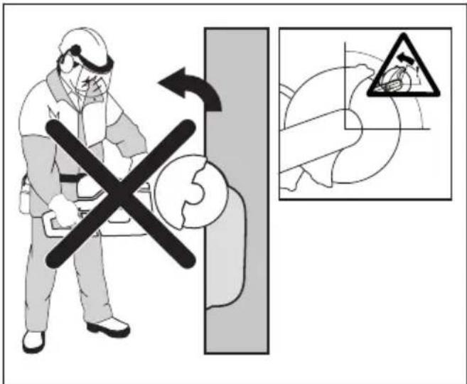
Pinching kickback
Pinching is when the cut closes and pinches the blade. If the blade is pinched or stalled the reactive force will be strong and you might not be able to control the power cutter.
natural_image
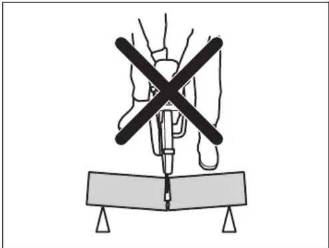
Diagram of a medical procedure with a surgical tool and X-shaped cross symbol above a table (no text or labels)If the blade is pinched or stalled in the kickback zone, the reactive force will push the power cutter up and back towards the user in a rotating motion causing serious or even fatal injury. Be alert for potential movement of the work piece. If the work piece is not properly supported and shifts as you cut, it might pinch the blade and cause a kick back.
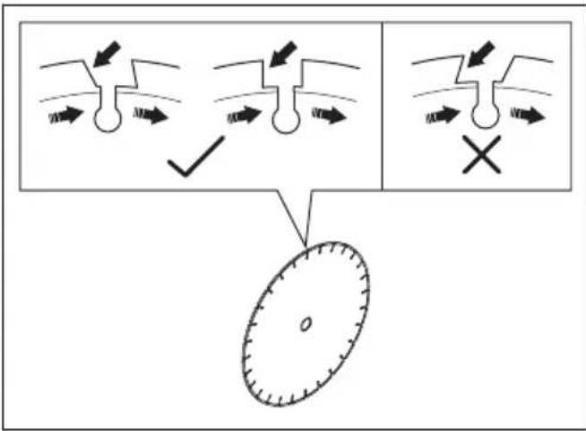
Pipe cutting
Special care should be taken when cutting in pipes. If the pipe is not properly supported and the cut kept open throughout the cutting, the blade might be pinched. Be especially alert when cutting a pipe with a belled end or a pipe in a trench that, if not properly supported, may sag and pinch the blade.
If the pipe is allowed to sag and close the cut, the blade will be pinched in the kick back zone and a severe kick back might develop. If the pipe is properly supported,
the end of the pipe will move downward, the cut will open and no pinching will occur.
Secure the pipe so it does not move or roll during cutting. Make sure that the cut opens to avoid pinching the blade.
To cut in smaller pipes

WARNING: If the blade is pinched in the kickback zone, it will cause a severe kickback.
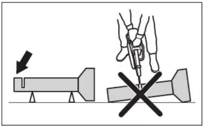
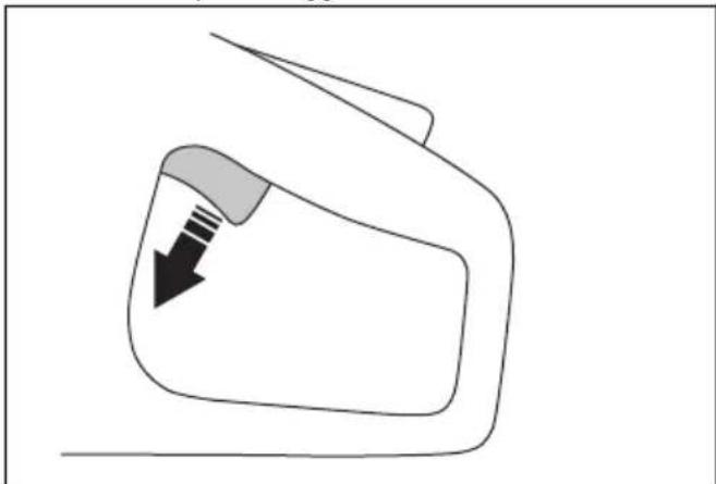
If the pipe is smaller than the maximum cutting depth of the product, the cutting operation can be done in 1 step from top to bottom.
- Cut the pipe from top to bottom.

natural_image
Simple line drawing of a device with a circular component and downward arrow, no text or symbols present.To cut in larger pipes

WARNING: If the blade is pinched in the kickback zone, it will cause a severe kickback.
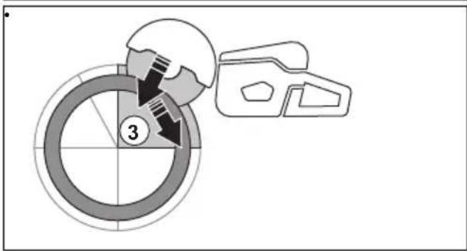
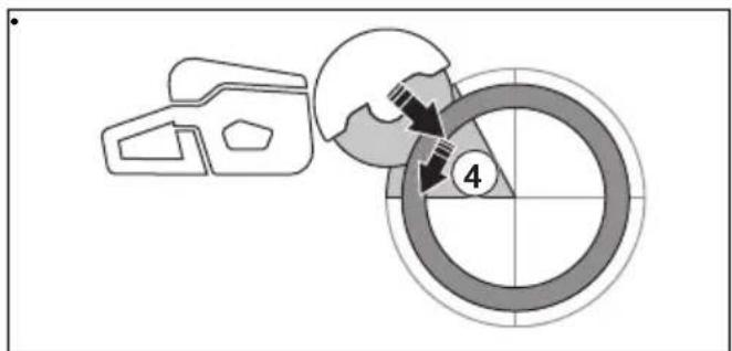
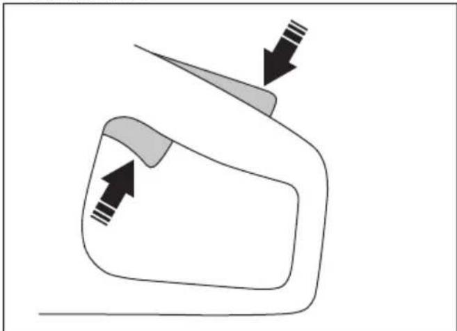
If the pipe is larger than the maximum cutting depth of the product, and can not be rolled, the cutting operation needs to be divided in 5 steps.
- Set the blade guard to pipe cutting mode. Refer to To set the pipe cutting mode (Only K1 PACE and K1 PACE Rescue) on page 25.
- Divide the pipe into 5 sections. Do a mark of those sections and of a cutting line. Cut a shallow guide groove around the pipe.
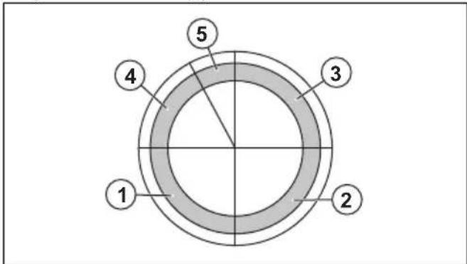
- Cut those sections in 5 steps with the cutting directions shown by the arrows in each step.
natural_image
Diagram showing a mechanical component with a circular target and directional arrows, no text or symbols present.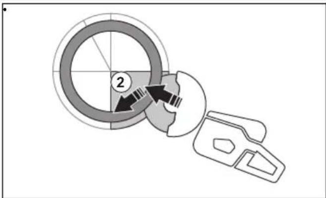
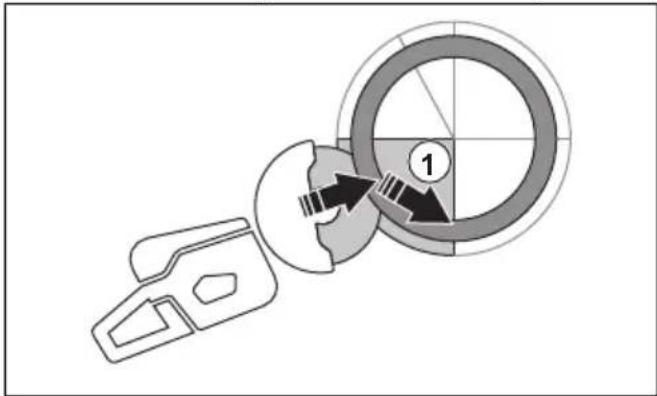
- Make the final separating cut from the top of the pipe pulling backwards, without involving the upper quadrant of the blade. Adjust the blade guard to full forward position for maximum protection.
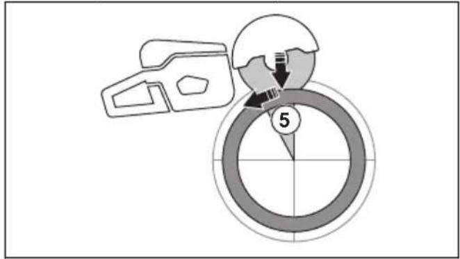

WARNING: If the pipe is properly supported, it should not pinch the blade when separated in section 5. However be alert if the blade is pinched during the final separation. If the blade is pinched in the lower section, the product may pull forward away from the operator, rather then resulting in a rotating kickback.
To prevent a kickback

WARNING: Avoid situations where there is a risk of kickback. Take care when using your power cutter and make sure that the blade is never pinched in the kickback zone.

WARNING: Be careful when you put the blade in an existing cut.

WARNING: Make sure that the work piece cannot move during a cutting operation.

WARNING: Only you and proper working technique can eliminate kickback and its dangers.
• Always support the work of piece so that the cut can keep open when cutting through. When the cut is open there is no kickback. If the cut is closed and pinches the blade, there is a risk of kickback.
natural_image
Two diagrams showing a cross-shaped object with arrows indicating direction, no text or symbols present.To do before you use the product
- Read the operator's manual carefully and make sure that you understand the instructions.
- Do the daily maintenance. Refer to Maintenance schedule on page 32.
- Make sure that only approved persons are in the work area.
- Make sure that you are in a safe and stable position during operation.
- Make sure that the water connector is connected to a water supply. Refer to To connect the coolant water on page 26.
- Do a check of the rear handle (A) to make sure that it is not damaged.
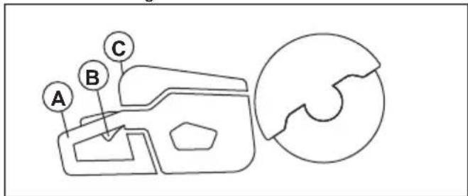
-
Do a check of the power trigger lockout (B) to make sure that it operates correctly and that it is not damaged.
-
Do a check of the control panel (C) to make sure that it operates correctly.
-
Make sure that all parts and guards are correctly attached and not damaged or missing.
-
Charge the battery and make sure that it is correctly attached to the product. Only use Husqvarna PACE approved batteries for the product.
-
Make sure that the power cutter stops when you release the power trigger.
To examine the direction of rotation of the cutting blade
- Find the arrow on the blade guard that shows the direction of rotation of the spindle shaft.
- Find the arrow on the cutting blade that shows the direction of rotation of the cutting blade.
- Make sure that the direction arrow of the cutting blade and the spindle shaft have the same direction.
To do a check of the arbor bushing
The arbor bushings are used to attach the product to the center hole of the cutting blade. The product is supplied with arbor bushings that are applicable for 20 mm / 0.79 in. or 25.4 mm / 1 in. center holes.
• Make sure that the dimension of the center hole of the cutting blade agrees with the installed arbor bushing. The diameter of the center hole is printed on the cutting blade.
- Use only HUSQVARNA arbor bushings.
Bluetooth® wireless technology
Products with built-in Bluetooth® wireless technology can connect to mobile devices. The symbol for Bluetooth® wireless technology comes on when your mobile device is connected to the product.

To use embedded connectivity with Husqvarna Fleet Services™
Note: This part is applicable only for products supplied with embedded connectivity.
Note: Radio transmission by the Bluetooth® function will be enabled on the first time of connection to a battery, and stay on after that.
-
Download the Husqvarna Fleet Services ^TM iOS or Android app Husqvarna Fleet Services.
-
Go to Husqvarna Fleet Services ™ website https://fleetservices.husqvarna.com for more information.
To connect the battery charger

WARNING: Only use the battery charge in ambient temperatures between 5°C/41°F and 40°C/104°F.
- Connect the battery charger to the voltage and frequency that is specified on the rating plate.
- Put the plug in a grounded socket outlet. The LED on the battery charger flashes green one time.
To connect the battery to the battery charger
Note: Charge the battery if it is the first time that you use it. A new battery is only 30% charged.
Note: The battery will not charge if the battery temperature is too high. Let the battery become cool before the battery charges
- Make sure that the battery is dry.
- Put the battery in the battery charger.
- Make sure that the green charging light on the battery charger comes on. That means that the battery is connected correctly to the battery charger.
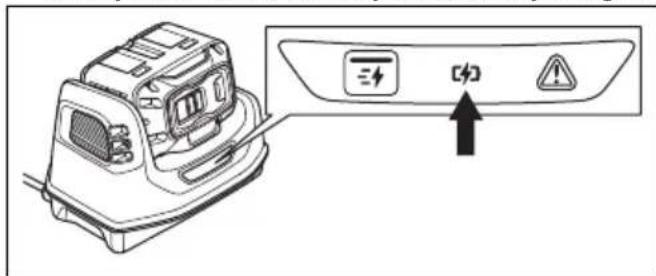
- When all LEDs on the battery come on, the battery is fully charged.
- To disconnect the battery charger from the mains socket, pull the plug. Do not pull the cable.
- Remove the battery from the battery charger.
Note: Refer to the battery and battery charger manuals for more information.
Basic working techniques

WARNING: Do not move the power cutter to the side. This can prevent the free movement of the blade and cause the blade to break, which can cause an injury.

WARNING: Do not use the side of the blade. The blade can become damaged and broken, which can cause an injury. Use only the cutting edge.

WARNING: Do not use a diamond blade to cut plastic material. The heat that occurs can melt the plastic. Melted plastic can attach to the cutting blade and cause a kickback.
• The product is made for high speed diamond blades, abrasive blades and recommended blades for the product. Use HUSQVARNA recommended cutting blades for the product.
- The product is made to cut into tiles, light concrete and stone. Use only for this type of operation.
• Make sure that the cutting blade does not show signs of damage and that it is attached correctly, refer to Abrasive blades on page 16 and To install the cutting blade on page 19.
• Always use the correct cutting blade for the type of operation, refer to Cutting blades on page 15.
- Do not cut asbestos material.
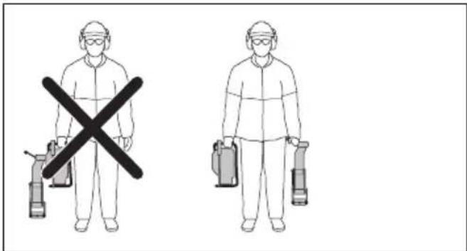
• Always hold the power cutter with 2 hands. Always hold the product tightly with thumbs and fingers around the handles. Always hold the rear handle with the right hand and the front handle with the left hand.
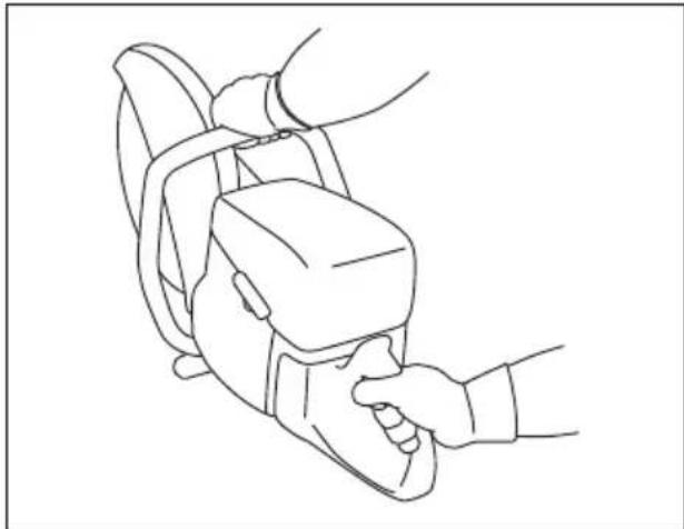
natural_image
Line drawing of a hand holding a device with a belt, no text or symbols present• Always be parallel to the cutting blade. Do not be linearly behind the cutting blade. If there is a kickback, the power cutter moves in the plane of the cutting blade.
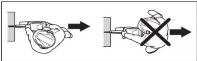
- Keep a safe distance to the cutting blade when the engine operates.
• Make sure that you are in a stable position during operation. - Keep applicable distance from the object you are cutting.
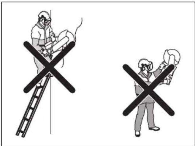
- Do not operate above shoulder height. Use a platform or scaffold if the cutting operation is above shoulder height. Do not overreach.
- Do not operate from a ladder.
- Make sure that the cutting blade is free when the engine is started.
• Always monitor the product when the engine operates. - Do not move the product when the cutting blade rotates. The product has a electrical retarder to decrease the blade stop time.
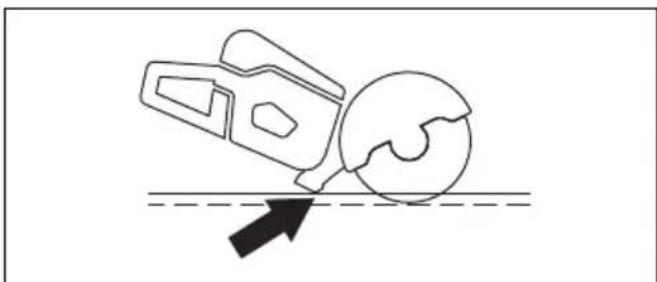
• Make sure that the front ground support is flush with the work piece at the rear. The blade guard collects spray and dust and keeps them away from the operator.
natural_image
Simple line drawing of a mechanical device and a sphere interacting with a surface, no text or symbols present.- Cut with full throttle. Keep full rotating speed until the cutting operation is completed.
- Push the cutting blade lightly against the object you are cutting. Do not use force.
- Align the cutting blade with the cut.

natural_image
Line drawing of a person using a tool on a bicycle, no text or symbols present- Move the cutting blade slowly forward and rearward to decrease the area between the cutting blade and the material. This decreases the temperature of the cutting blade.

- Do not cut with the kickback zone of the blade, see Kickback zone on page 20.
To set the pipe cutting mode (Only K1 PACE and K1 PACE Rescue)

WARNING: The adjustment handle for blade guard can be very hot, use gloves when you adjust the blade guard.

WARNING: Only use pipe cutting mode during pipe cutting operation. In all other operations you must use standard cutting mode
The pipe cutting mode enables pipe cutting in the kickback zone.
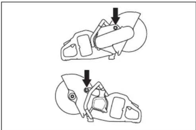
- Move the stop bolt of the blade guard from the standard cutting mode (A) to the pipe cutting mode (B).
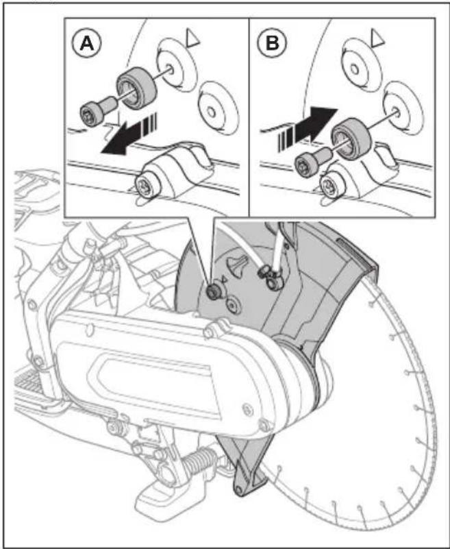
- Pull the adjustment handle to enable the pipe cutting mode.
natural_image
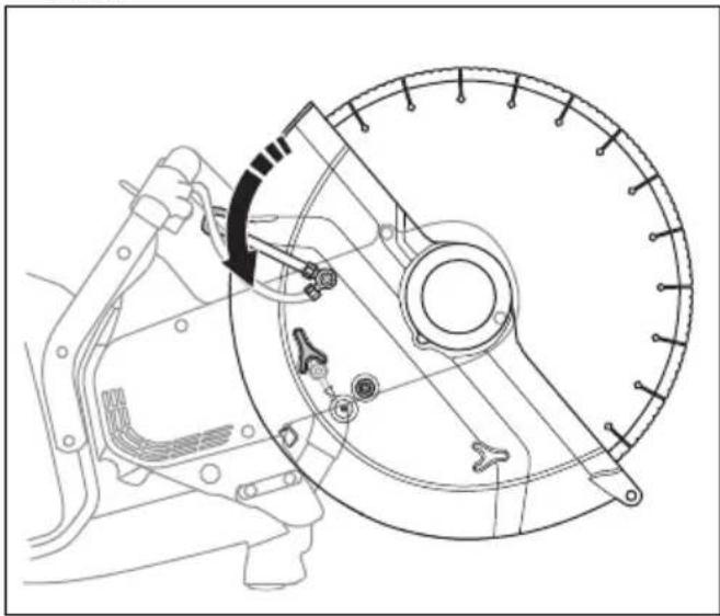
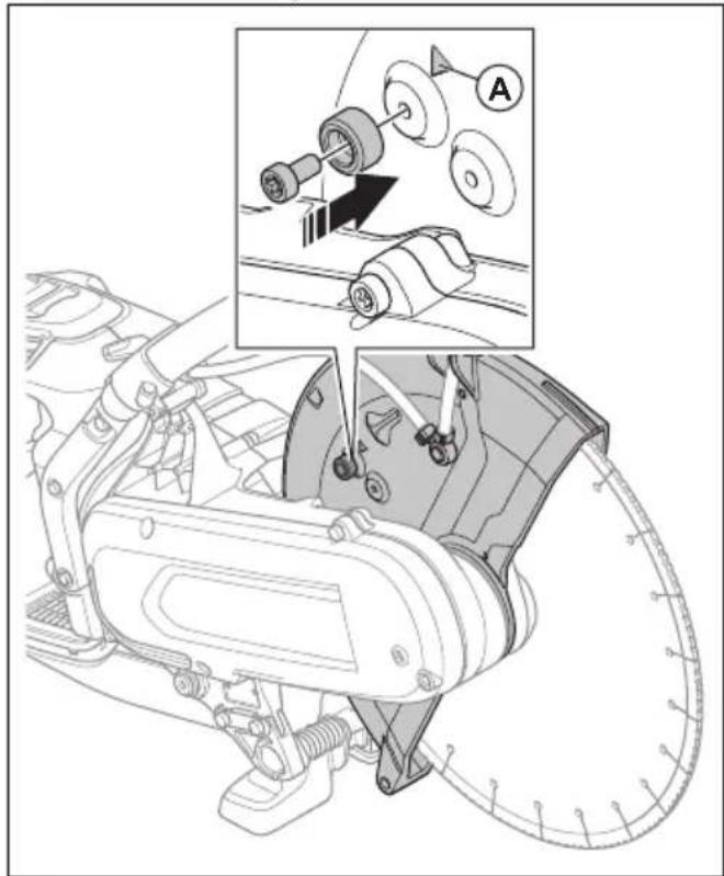
Technical line drawing of a mechanical assembly with no visible text or symbols- Put back the stop bolt to the standard cutting mode after the pipe cutting operation. The arrow (A) shows the standard cutting mode.
natural_image
Technical diagram of a mechanical assembly with labeled parts and an inset showing a close-up of a component (no text or symbols present)Wet cutting

CAUTION: Do not use Vac equipment together with the wet system.
- Diamond blades for wet cutting must be used with the wet system.
• Water cool the blade and increases its service life while also decrease the dust. - When wet cutting, make sure to collect the waste water safely.
To decrease dust during operation
The product has a wet cutting kit to decrease harmful dust in the air during operation. The wet cutting kit has low water consumption.
- When possible, use wet cutting blades with water cooling. Refer to Diamond blades for wet cutting on page 17.
- Adjust the water flow with the valve. The correct flow is different for different types of tasks.
- Make sure that the water pressure is correct. Refer to Technical data on page 38. If the water hose comes off at the supply source, the supplied water pressure can be too high.
To connect the coolant water
- Connect the water hose to the water supply (A).
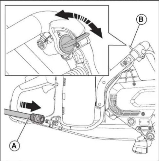
- Turn the water valve (B) to start or stop the water flow.
- Examine the water connection and the hose for leakage.
- Make sure that the water pressure is not higher than the maximum permitted water pressure, refer to Technical data on page 38.
Dry cutting
- When dry cutting, lift the blade out from the cut each 30–60 seconds and let it rotate in the air for 10 seconds to let it cool.
- Use Vac equipment if possible.
To start the product
-
Do a check of the power trigger and power trigger lockout. Refer to To do a check of the power trigger lockout on page 33.
-
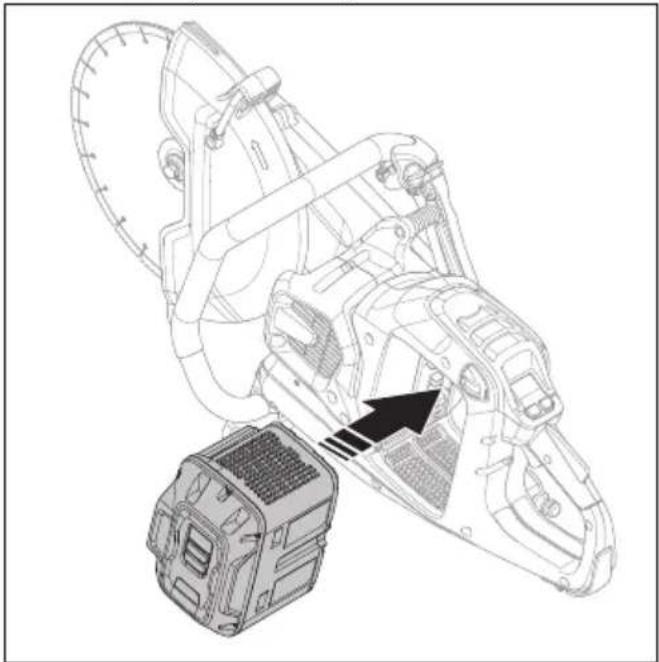
Put the battery in the battery holder.
natural_image
Technical line drawing of a mechanical device with a base and gear assembly, no visible text or symbols- Push the battery until you hear a click sound. If the battery does not move into the battery holder easily, it is not attached correctly into the battery holder.
natural_image
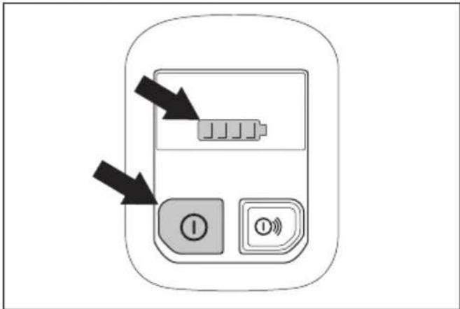
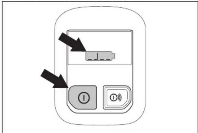
Line drawing of a hand inserting a component into a vehicle chassis (no text or symbols)- Push and hold the On/Off button until the battery status indicator comes on.
- Push the power trigger and power trigger lockout to start the motor.
natural_image
Simple line drawing of a car's side profile with arrows indicating movement or force (no text or symbols)To stop the product
- Release the power trigger.
natural_image
Simple line drawing of a car's side panel with a black arrow indicating the left side (no text or symbols)- Push and hold the On/Off button on the control panel until the battery status indicator goes off.
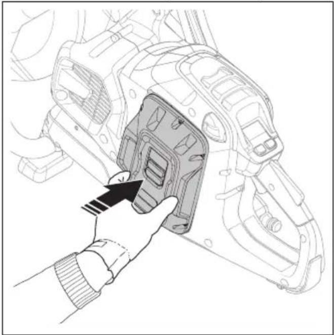
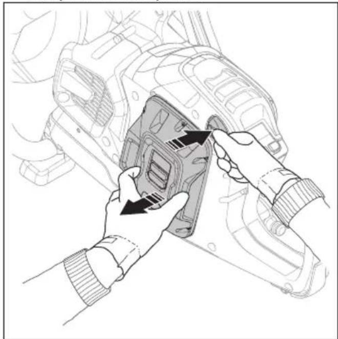
- Push the battery release button and remove the battery from the battery holder.
natural_image
Illustration of hands installing or adjusting a mechanical component with arrows indicating assembly (no text or symbols present)
WARNING: Remove the battery when you do not use or when you do not have full vision of the product. This is to prevent accidental start.
Rail cutting (K1 PACE Rail)
General
A rail fixture is used with rail power cutters to cut railroad tracks. Always cut railroad tracks with abrasive blade and no water. Speak to your servicing dealer for more information about different rail fixtures.

WARNING: Always use protective gloves when you assemble or disassemble the product.

CAUTION: Do not install the rail fixture on the product during transport or when you move the product. When the product and the rail fixture are put together, there is a larger risk of damage than when they are disconnected. Damages, such as bent parts, can result in less accurate cuts.
Installation points and rail fixture indicator
K1 PACE Rail has 2 installation points for the rail fixture, on the left side and on the right side of the product.
natural_image
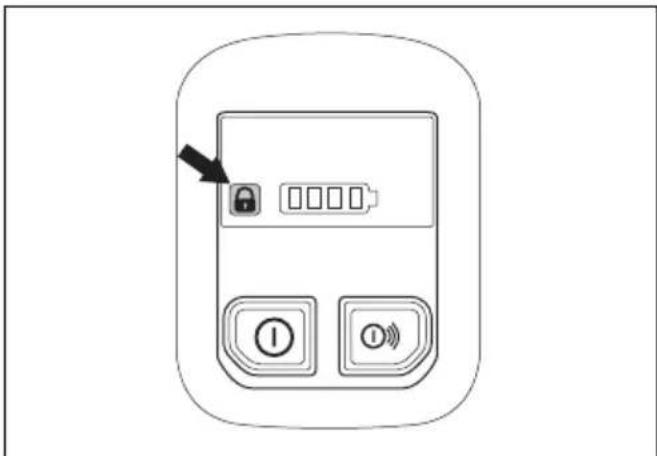
Technical line drawing of two mechanical components with arrows indicating assembly or movement (no text or symbols)The rail fixture indicator shows if the rail fixture is attached or not attached to the product. When the rail fixture is correctly attached to the product, the indicator goes off. When the rail fixture is not attached to the product, the indicator is on.
natural_image
Line drawing of a mobile phone control panel with buttons and an arrow pointing to the lock (no text or symbols)To install the rail fixture RA 10, RA 10S

CAUTION: Install the rail fixture to the rail before you install the product to the rail fixture. There is a risk that the rail fixture is not installed at a correct angle if the product is installed first.
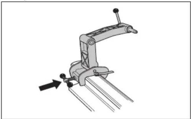
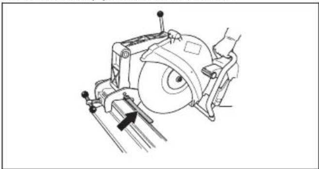
- Attach the rail fixture to the rail. Tighten the handle fully.
natural_image
Mechanical clamp mechanism diagram showing lever and guide assembly (no text or symbols)- Install the product on the rail fixture with the right side of the product against the rail fixture.
natural_image
Technical line drawing of a mechanical cutting tool with a circular blade and clamp (no text or symbols)Note: It is also possible to install the product with the left side against the rail fixture, but we recommend to use the right side when possible.
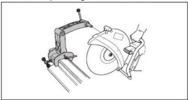
To install the rail fixture RA 11

CAUTION: Install the rail fixture to the rail before you install the product to the rail fixture. There is a risk that the rail fixture is not installed at a correct angle if the product is installed first.
- Attach the rail fixture to the rail. Tighten the handle fully.
natural_image
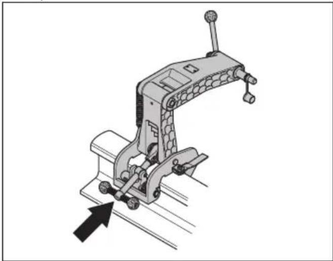
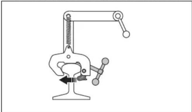
Mechanical clamp device with directional arrow indicating movement (no text or symbols)- Make sure that the claw is tightly attached to the rail.
natural_image
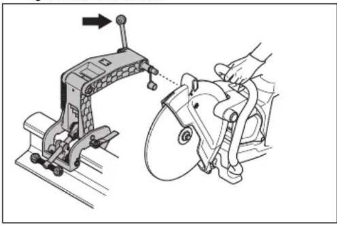
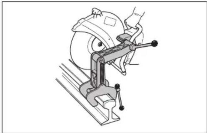
Simple line drawing of a mechanical clamp or clamping device with no text or symbols- Attach the right side of the product to the rail fixture. Tighten the lock handle.
natural_image
Technical illustration of a mechanical device with a hand operating it, showing assembly and mounting (no text or symbols)Note: It is also possible to install the product with the left side against the rail fixture, but we recommend to use the right side when possible. Refer to Installation points and rail fixture indicator on page 28.
To prepare the cutting guide
Note: The first time you use the rail system, you must cut the cutting guide.
The cutting guide helps the operator to put the cutting blade in correct position for the cut.
- Fold out the cutting guide.
- Put the cutting guide parallel to the rail.
natural_image
Technical line drawing of a mechanical device with a circular component and directional arrow (no text or symbols)- Carefully cut off the cutting guide.
To use the rail fixture RA 10, RA 10S
- Fold out the cutting guide.
- Align the saw cut and fold in the cutting guide.
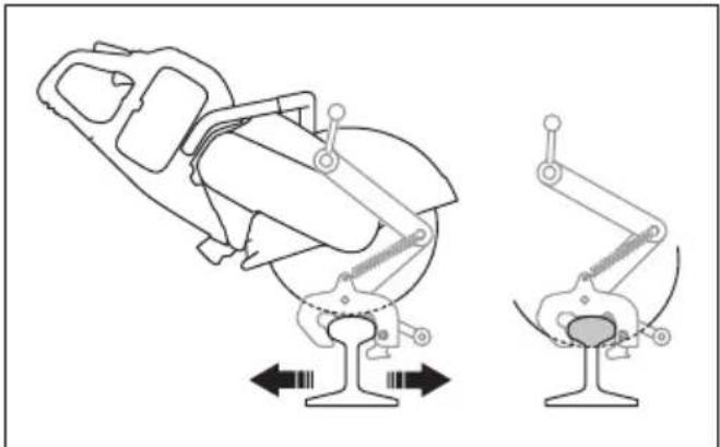
- Move the product rearward and forward to decrease the contact surface between the cutting blade and the rail. More contact surface increases the risk of glazing the cutting blade or making it blunt.

natural_image
Technical line drawing of a mechanical device with two views showing internal components (no text or symbols)- Cut the rail.

a) Cut through the section at the top (A).
b) Cut through the section in the middle (B).
c) Cut through the section in the bottom (C).
- If the cut cannot be completed from 1 side, the product must be turned around.
a) Stop the product. Refer to To stop the product on page 27.
b) Remove the product from the rail fixture.
c) Install the product with its left side to the rail fixture.
natural_image
Technical line drawing of a mechanical clamp or clamping device with a circular component on top (no text or symbols)d) Adjust the position of the cutting blade, if it is necessary. Loosen the 2 crews (A) and adjust (B) the position of the cutting blade.
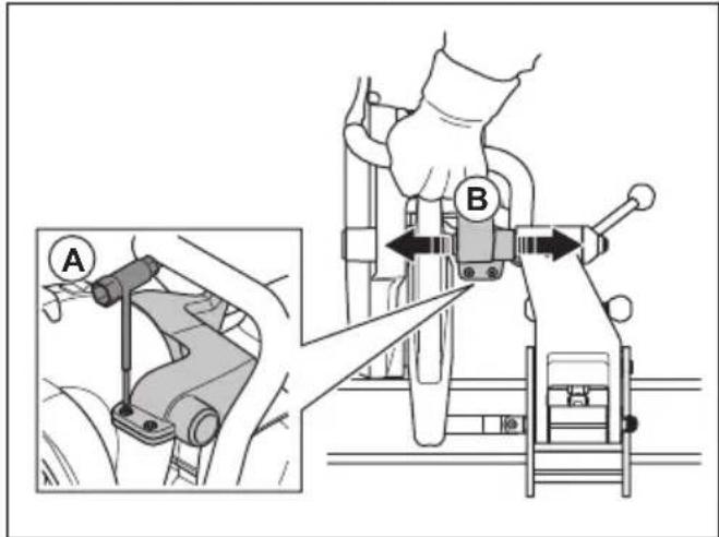
e) Tighten the 2 screws (A).
f) Continue to cut.
natural_image
Three abstract line drawings of mechanical components or structural elements, no text or symbols present- Complete the cut.
- Stop the product.
- Remove the product from the rail fixture.
- Remove the rail fixture from the rail.
To use the rail fixture RA 11
- Fold out the cutting guide.
-
Align the saw cut and fold in the cutting guide.
-
Move the product rearward and forward to decrease the contact surface between the cutting blade and the rail. More contact surface increases the risk of glazing the cutting blade or making it blunt.
natural_image
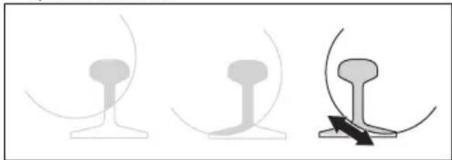
Technical line drawing of a mechanical device with two views showing different configurations (no text or symbols)- Cut the rail.

a) Cut through the section at the top (A).
b) Cut through the section in the middle (B).
c) Cut through the section in the bottom (C).
- If the cut cannot be completed from 1 side, the product must be turned around.
a) Stop the product. Refer to To stop the product on page 27.
b) Remove the product from the rail fixture.
c) Install the product with its left side to the rail fixture.
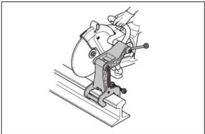
natural_image
Illustration of a hand operating a mechanical clamp or presser on a platform (no text or symbols visible)d) Put the cutting blade against the rail and make sure that it is in the center of the cut.
e) Adjust the position of the cutting blade, if it is necessary. Loosen the 2 crews (A) and adjust (B) the position of the cutting blade.
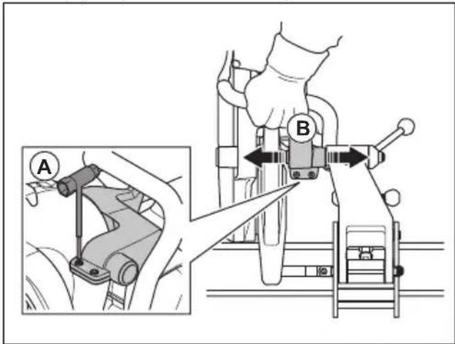
f) Tighten the 2 screws (A)
g) Continue to cut.
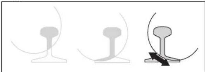
natural_image
Three abstract line drawings showing different mechanical or structural configurations (no text or symbols)- Complete the cut.
- Stop the product.
- Remove the product from the rail fixture.
- Remove the rail fixture from the rail.
To cut rail, recommendations
Note: With correct cutting technique, the time to cut a 50 kg/m rail is 1-2 minutes and to cut 60 kg/m rail is 1.5-2.5 minutes. If more time is necessary, do a check of the cutting technique and the cutting blades. Incorrect cutting technique causes problems, such as cuts that are not accurate. An incorrect, blunt or worn cutting blade can also cause cuts that are not accurate.
-
To get accurate cuts, only use high quality cutting blades that are made specially to cut rail.
• To make straight cuts, start with these steps: -
Make sure that the rail fixture is correctly installed.
- Apply full throttle until the blade is at full speed.
- Start to cut.
- Move the product forward and rearward over the rail.
- Apply full throttle and keep full speed until the cut is completed.
- Hold the product handle with your hands aligned with the cutting blade. This gives a straight cut and decreases the wear on the cutting blade.
Maintenance
Introduction

WARNING: Read and understand the safety chapter before you do maintenance work on the product.
cycle and increase the risk of accidents. All servicing and/or repair work must also be done by a professional. Turn to your servicing dealer for more information.

WARNING: Remove the battery before you do maintenance on the product.
Maintenance schedule
The following is a list of the maintenance steps that you must do on the product.

WARNING: Failure to do maintenance correctly can decrease the product life
| Maintenance Before | use | After use | Monthly |
| Clean the external parts of the product. X | |||
| Make sure that the power trigger and the power trigger lockout function correctly from a safety point of view. | X | ||
| Do a check of the cutting blade. Look for cracks and make sure that the cutting blade is not unusually worn. Replace if necessary. | X | ||
| Do a check of the blade guard. X | |||
| Do a check of the belt guard. X | |||
| Do a check of the vibration damping system. X | |||
| Clean the fan housing on the product. X | |||
| Make sure that the screws and nuts are tight. X | |||
| Make sure that the control panel works correctly and that it is not damaged. X | |||
| Do a check of the connections between the battery and the product. Do a check of the connection between the battery and the battery charger. | X | ||
| Blow through the product and battery soft with compressed air. X | |||
| Clean the product. X | |||
| Replace damaged parts. X |
To clean externally

WARNING: Do not use a high-pressure washer to clean the product.
- Flush the product externally with clean water after each day of operation. If it is necessary, use a brush.
To do a check of the power trigger lockout
- Make sure that the power trigger and power trigger lockout move freely and that the return spring operates correctly.
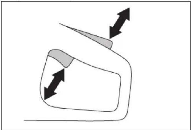
natural_image
Simple line drawing of a vehicle or road with directional arrows indicating movement (no text or symbols)- Push down the power trigger lockout and make sure that it goes back to its initial position when you release it.
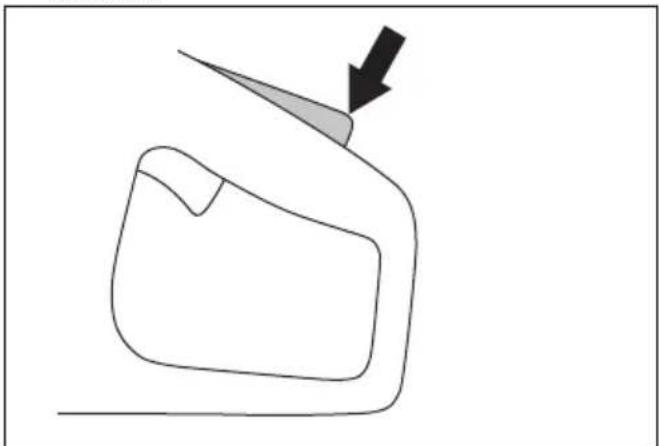
natural_image
Simple line drawing of a mechanical part with an arrow indicating direction (no text or symbols)- Make sure that the power trigger is locked at the idle position when the power trigger lockout is released.
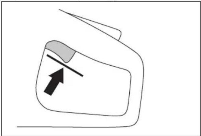
natural_image
Simple line drawing of a device with an arrow pointing to a component (no text or symbols)- Push and hold the On/Off button to start the product and apply full power. Refer to To start the product on page 26.
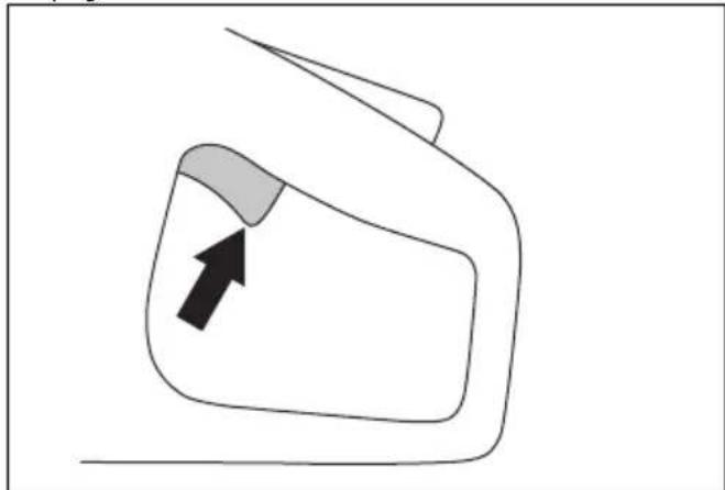
natural_image
Simple line drawing of a car front view with an arrow pointing to the side panel (no text or symbols)- Release the power trigger and make sure that the cutting blade stops. If the cutting blade rotates when the power trigger is in the idle position, speak to your servicing dealer.
To clean the battery and the battery charger

WARNING: Do not clean the battery or the battery charger with water.

WARNING: Do not use any chemical substances to clean the battery.
• Make sure that the battery and the battery charger are clean and dry before you put the battery into the battery charger.
- Clean the battery terminals with compressed air or use a soft and dry cloth.
- Clean the surfaces of the battery and the battery charger with a soft and dry cloth.
To do a check of the battery charger
- Make sure that the battery charger and the power supply cord is not damaged. Look for cracks and other damage.
To clean the cooling system
The product has a cooling system that keeps the temperature of the product as low as possible.
The cooling system includes an air intake on the left side of the product and a fan on the motor.

natural_image
Technical line drawing of a mechanical device with no visible text or symbols-
Clean the cooling system with a brush weekly or more frequently if necessary.
-
Make sure that the cooling system is not dirty or blocked.

CAUTION: A dirty or blocked cooling system can cause the product to become too hot.
To remove the drive belt
-
Remove the belt guard. Refer to Product overview K1 PACE on page 3.
-
Put the belt tool on top of the front pulley. Use a wrench to pull the drive belt off the pulley.
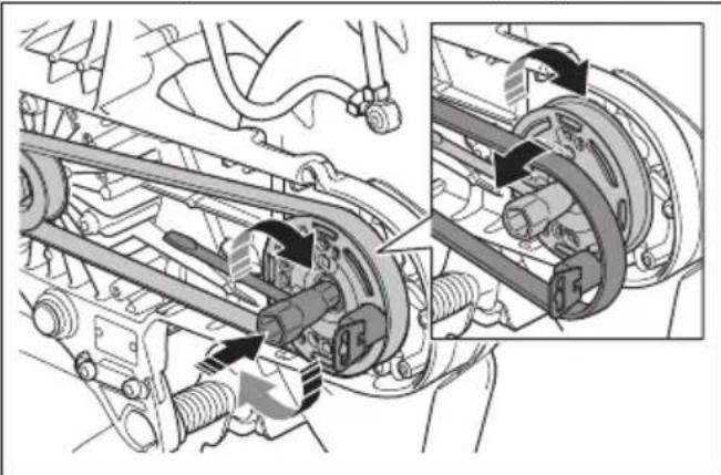
natural_image
Mechanical assembly diagram showing a motor drive system with attached components and a close-up inset of the motor assembly (no text or labels visible)To install the drive belt
-
Put the drive belt around the rear pulley.
-
Put the belt assembly tool on top of the front pulley.
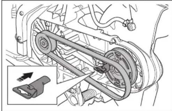
natural_image
Mechanical assembly diagram showing a belt drive mechanism with no visible text or symbols- Turn the front pulley clockwise with the combination wrench. At the same time, push the drive belt onto the pulley.
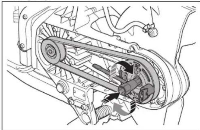
natural_image
Mechanical assembly diagram showing a belt drive mechanism with no visible text or symbols- Attach the belt guard. Refer to Product overview K1 PACE on page 3.
To do a check of the water supply system
- Examine the nozzles on the blade guard and make sure that they are not clogged.
- Clean as necessary.
- Examine the filter on the water connector. Make sure that it is not clogged.
- Clean as necessary.
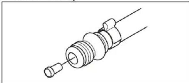
natural_image
Technical line drawing of a mechanical component with threaded end and shaft (no text or symbols)- Examine the hoses and make sure that they are not damaged.
Troubleshooting
Troubleshooting of the product
Note: For troubleshooting of the battery and the battery charger refer to related operator's manual.
| Symbol on the control panel | Problem Cause Solution | |||
| The product does not start. No LEDs come on when you push the On/Off button. | The battery is empty. Charge | the battery. | ||
| The battery is not correctly installed in the product. | Remove the battery and install it correctly. | |||
| The battery is damaged or does not operate correctly. | Push the On/Off button to do a check of the battery.A minimum of 1 green LED must come on. | |||
| Dirty or damaged plug between battery and product. | Make sure that the power connectors between the battery and the product are not dirty or damaged. | |||
| Servicing is necessary. Speak | to an approved Husqvarna service center. | |||
| No reaction from the motor when you push the power trigger. | Servicing is necessary. Speak | to an approved Husqvarna service center. | ||
| The motor makes a sudden movement when you push the power trigger, then stops. | Servicing is necessary. Speak | to an approved Husqvarna service center. | ||
| The product stops when you apply work load. | You have put too high load on the product. | Start the product and use less load. | ||
| The product operates but there is no indication light on the control panel. | Servicing is necessary. Speak | to an approved Husqvarna service center. | ||
 | The warning indicator flashes red. Temporary warning. | Temperature deviation, if the temperature warning indicator is also on. | Let the product cool down if it is too hot. If it is too cool, put it indoors to warm up. | |
| Damaged battery. Replace the battery. | ||||
| Incorrect direction of rotation. | The product stops. Pull the power trigger to reset. | |||
| The power trigger is pushed during startup. | Release the power trigger during startup. | |||
| The power trigger and the On/Off button are pushed at the same time. | Release the power trigger. | |||
| The red warning indicator is on | Servicing is necessary. Speak | to an approved Husqvarna service center. | ||
| Symbol on the control panel | Problem Cause Solution | |||
 | The yellow temperature warning indicator is on. | Temperature deviation. The | product is too hot or too cold. | |
 | The X-Halt indicator flashes. | The X-Halt function is engaged. | Wait for the cool down period to complete. | |
| The X-Halt indicator is on. Servicing is necessary. Speak to an approved Husqvarna service center. | ||||
 | 1 green LED flashes. Low battery voltage. Charge the battery. | |||
| All green LEDs flash. Servicing is necessary. Speak to an approved Husqvarna service center. | ||||
| LED 3 flashes and LED 4 is on permanently. | Servicing is necessary. Speak to an approved Husqvarna service center. | |||
 | Rail fixture indicator is on when the rail fixture is attached to the product. | The rail fixture is not attached correctly. | Make sure that the rail fixture touches the bottom end of the installation point on the product. If the rail fixture indicator is still on, try the second installation point. | |
| If the rail fixture indicator goes off when it is attached to the second installation point, this installation point operates correctly. Speak to an approved Husqvarna service center. | ||||
Transportation, storage and disposal
Transportation and storage

CAUTION: Do not install the rail fixture to the product during transport of the product. The rail fixture is a precision tool. A damaged tool gives less accurate cuts.
- Attach the product safely during transportation to prevent damage and accidents.
- Remove the cutting blade before transportation or storage of the product.
- Keep the product in a locked area to prevent access for children or persons that are not approved.
- Keep the cutting blades in dry, frost free conditions.
- Examine all new and used blades for transport and storage damage before assembly.
-
Clean the product and do the maintenance before storage. Refer to Maintenance schedule on page 32.
-
Disconnect the battery from the product.
- When you put the K1 PACE Rail in its transportation box, make sure that the rail fixture and the product do not touch.
Disposal of the battery, battery charger and product
The symbol below means that the product is not domestic waste. Recycle it at a recycling station for electrical and electronic equipment. This helps to prevent damage to the environment and to persons.
Speak to local authorities, domestic waste service or your dealer for more information.
Note: The symbol shows on the product or package of the product.
Technical data
| HUSQVARNA K1 PACE, K1 PACE Rescue and K1 PACE Rail | ||
| Voltage d.c. maxi-mum/nominal, V | 109.2/93.6 | |
| Weight, kg/lbs | K1 PACE 12 in. 7.2/15.8 | |
| K1 PACE 14 in. 7.4/16.3 | ||
| K1 PACE Rescue 12 in. 7.7/17 | ||
| K1 PACE Rescue 14 in. 7.9/17.4 | ||
| K1 PACE Rail 14 in. 8.6/18 | ||
| RA 10S 5.3/11.7 | ||
| RA 11 5.8/12.8 | ||
| Maximum cutting depth, mm/in. | K1 PACE 12 in., flange washer 60 mm/2.4 in. 121/4.8 | |
| K1 PACE 14 in., flange washer 60 mm/2.4 in. 145/5.7 | ||
| K1 PACE Rail 14 in., flange washer 90 mm/3.5 in. 133/5.2 | ||
| Maximum blade di-ameter, mm/in. | K1 PACE 12 in. 314/12.4 | |
| K1 PACE 14 in. 361/14.2 | ||
| K1 PACE Rescue 12 in. 314/12.4 | ||
| K1 PACE Rescue 14 in. 361/14.2 | ||
| K1 PACE Rail 14 in. 356/14 | ||
| Minimum flange washer diameter, mm/in. | Diamond blades 12 in. and 14 in. 60/2.4 | |
| Abrasive blade 12 in. 76.5/3 | ||
| Abrasive blade 14 in. 90/3.5 | ||
| Maximum blade thickness, mm/in. | Abrasive blades 4.0/0.16 | |
| Diamond blades 2.8/0.11 | ||
| Blade shaft, rpm no load | 12 in. 3800 | |
| 14 in. 3400 | ||
| Water cooling of blade, K1 PACE, K1 PACE Rescue Yes | ||
| Connecting nipple, K1 PACE, K1 PACE Rescue Type "Gardena" | ||
| Recommended water pressure, K1 PACE, K1 PACE Rescue, bar/psi 0.5-6/7.3-87 | ||
| Vibration levels, ahveq1 | K1 PACE, K1 PACE Rescue 12in. Front, m/s2 | 2.0 |
| K1 PACE, K1 PACE Rescue 12in. Rear, m/s2 | 1.1 | |
| K1 PACE, K1 PACE Rescue 14in. Front, m/s2 | 2.2 | |
| K1 PACE, K1 PACE Rescue 14in. Rear, m/s2 | 1.2 | |
| K1 PACE Rail 14in. Front, m/s2 | 2.8 | |
| K1 PACE Rail 14in. Rear, m/s2 | 1.7 | |
| Noise emissions2 | K1 PACE, K1 PACE Rescue LpA, dB(A) 102 | |
| K1 PACE, K1 PACE Rescue LwA, dB(A) 113 | ||
| K1 PACE Rail LpA, dB(A) 101 | ||
| K1 PACE Rail LwA, dB(A) 113 | ||
| Husqvarna Fleet ServicesTM | Yes | |
| Installed arbor bush-ing diameter, mm/in. | K1 PACE 12in., K1 PACE 14in.,K1 PACE Rescue, K1 PACE Rail 25.4/1 | |
| K1 PACE 12in. UK 20/0.8 | ||
| IP class IPx4 | ||
| Torque for blade bolt, Nm/ft-lb 30/18.5 | ||
Noise and vibration declaration statement
These declared values were obtained by laboratory type testing in accordance with the stated directive or standards and are suitable for comparison with the declared values of other products tested in accordance with the same directive or standards. These declared
values are not suitable for use in risk assessments and values measured in individual work places may be higher. The actual exposure values and risk of harm experienced by an individual user are unique and depend upon the way the user works, in what material the product is used, as well as upon the exposure time and the physical condition of the user, and the condition of the product.
Embedded connectivity
Note: This part is applicable only for products supplied with embedded connectivity.
| BLE technology radio spectrum | |
| Frequency bands for the tool, GHz 2.402-2.480 | |
| Maximum radio-frequency power transmitted, dBm/mW 4/2.5 | |
Accessories
Approved batteries for the product
| Husqvarna PACE battery Husqvarna B380X PACE Husqvarna B750X PACE | |
| Type Lithium-ion Lithium-ion | |
| Battery capacity, Ah 4 8 | |
| Nominal voltage, V 94 94 | |
| Weight, kg / lb 3.1 / 6.1 5.1 / 11.4 |
Approved battery chargers for the product
| Husqvarna PACE battery charger | Husqvarna C900X PACE Husqvarna C1800X PACE |
| Mains voltage, V 100-240 | 220-240 |
| Frequency, Hz 50-60 50-60 | |
| Power, W 900 | 1800 |
Vacuum attachment ( K1 PACE, K1 PACE Rescue)
Use the vacuum attachment to connect a dust extractor to the product.
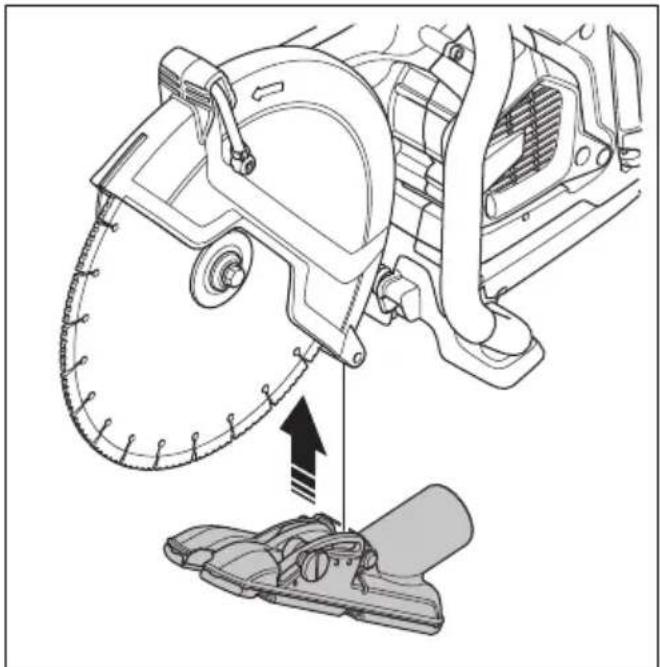
natural_image
Technical illustration of a mechanical assembly with a saw cutting tool and a foot pusher (no text or symbols)Wheel kit
The wheel kit is attached at the bottom of the product.
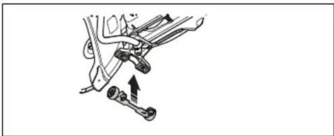
natural_image
Mechanical assembly diagram showing a lever mechanism with no text or symbolsService
Approved service center
To find your nearest Husqvarna approved service center, go to the web site www.husqvarnaconstruction.com.
Declaration of Conformity
EU Declaration of Conformity
We, Husqvarna AB, SE-561 82 Huskvarna, Sweden, tel: +46-36-146500, declare on our sole responsibility that the product:
| Description Portable cut-off machine | |
| Brand HUSQVARNA | |
| Type/Model K1 PACE, K1 PACE | Rescue, K1 PACE Rail |
| Identification Serial numbers dating | from 2023 and onwards |
complies fully with the following EU directives and regulations:
| Directive/Regulation Description | |
| 2006/42/EC "relating to machinery" | |
| 2014/53/EU "relating to radio equipment" | |
| 2011/65/EU "relating to restriction of hazardous substances" |
and that the following standards and/or technical specifications are applied;
EN ISO 12100:2010
EN 60745-2-22:2011/A11:2013
EN 55014-1:2017
EN 55014-2:2015
ETSI EN 301 489-1 V2.2.3
ETSI EN 301 489-17 V3.2.4
ETSI EN 300 328 V2.2.2
EN IEC 63000:2018
EN 13977:2011, only applicable for K1 PACE Rail
Partille, 2023-06-22

Fredrik Sandinge
R&D Director, Concrete Sawing & Drilling Equipment
Husqvarna AB, Construction Division
Responsible for technical documentation

UK Declaration of Conformity
We, Husqvarna AB, SE-561 82 Huskvarna, Sweden, tel:
+46-36-146500, declare on our sole responsibility that
the product:
| Description Portable cut-off machine | |
| Brand HUSQVARNA | |
| Type/Model K1 PACE, K1 PACE | Rescue, K1 PACE Rail |
| Identification Serial numbers dating from 2023 and onwards | |
complies fully with the following EU directives and
regulations:
| Description |
| The Supply of Machinery (Safety) Regulations 2008 |
| The Radio Equipment Regulations 2017 |
| The Restriction of the Use of Certain Hazardous Substances in Electrical and Electronic Equipment Regulations 2012 |
and that the following standards and/or technical specifications are applied;
EN ISO 12100:2010
EN 60745-2-22:2011/A11:2013
EN 55014-1:2017
EN 55014-2:2015
ETSI EN 301 489-1 V2.2.3
ETSI EN 301 489-17 V3.2.4
ETSI EN 300 328 V2.2.2
EN IEC 63000:2018
EN 13977:2011, only applicable for K1 PACE Rail
Partille, 2023-06-22
UK Importer:
Husqvarna UK Ltd
Preston Road, Co. Durham
DL5 6UP

Fredrik Sandinge
R&D Director, Concrete Sawing & Drilling Equipment
Husqvarna AB, Construction Division
Responsible for technical documentation

Registered trademarks
The Bluetooth® word mark and logos are registered trademarks owned by Bluetooth SIG, inc. and any use of such marks by HUSQVARNA is under license.
Inhalt
natural_image
Illustration of a person in full safety gear holding a first aid kit (no text or symbols present)Gashebelsperre
natural_image
Simple line drawing of a 3D object with an arrow pointing to a circular shape (no text or symbols)natural_image
Illustration of five different types of threaded screw or plug components (no text or symbols)natural_image
Technical line drawing of two interlocking gears with no text or symbolsnatural_image
Diagram of a geological cross-section showing layered strata with no text or symbolsnatural_image
Circular mechanical gear diagram with evenly spaced teeth and central bore (no text or symbols)
natural_image
Abstract black X-shaped line with zigzag extension and a small circle below (no text or symbols)natural_image
Diagram of a medical device with two circular components and directional arrows indicating movement or force (no text or symbols)natural_image
Line drawing of a mechanical device with a circular component and connecting rod (no text or symbols)natural_image
Technical line drawing of a mechanical device with two arrows indicating directional components (no text or symbols present)Betrieb
Einleitung

natural_image
Diagram showing a mechanical component and a circular object with directional arrows, no text or symbols present.Blockierung
natural_image
Diagram of a medical device with a cross symbol crossed over a table, no text or labels presentnatural_image
Simple line drawing of a device with a magnified circular section showing a downward arrow and ring (no text or symbols)natural_image
Diagram showing a mechanical component with a circular target and directional arrows, no text or symbols present.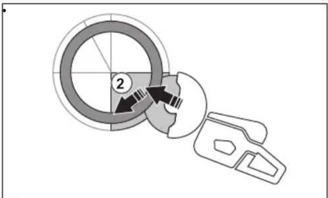
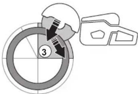
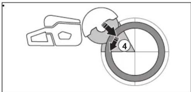
natural_image
Two diagrams showing a beam with a cross symbol and a U-shaped object under force, no text or labels present.natural_image
Line drawing of a hand holding a device with a belt, no text or symbols presentnatural_image
Simple line drawing of a mechanical device and a sphere above a dashed line, with an arrow pointing to the sphere (no text or symbols)natural_image
Line drawing of a person using a footlifter to lift a bicycle (no text or symbols)natural_image
Technical line drawing of a mechanical assembly with no visible text or symbolsnatural_image
Technical diagram of a mechanical assembly with component details and an inset showing a disassembly or assembly process (no text or symbols present)Nassschneiden

natural_image
Technical line drawing of a mechanical device with a base and gear assembly, no visible text or symbolsnatural_image
Line drawing of a hand inserting a plastic component into a vehicle chassis (no text or symbols)natural_image
Simple line drawing of a car's side profile with arrows indicating motion or force (no text or symbols)natural_image
Simple line drawing of a car door with a black arrow pointing to the side panel (no text or symbols)natural_image
Illustration of hands installing or adjusting a mechanical component with arrows indicating assembly (no text or symbols present)
natural_image
Diagram showing two mechanical components with arrows indicating motion or assembly, no text or symbols presentnatural_image
Diagram of a device control panel with two buttons and a lock icon, no text or symbols presentnatural_image
Mechanical clamp mechanism diagram showing lever and guide assembly (no text or symbols)natural_image
Technical line drawing of a mechanical device with a circular component and lever mechanism (no text or symbols)natural_image
Mechanical clamp device with directional arrow indicating movement (no text or symbols)natural_image
Simple line drawing of a mechanical clamp or clamping device with no text or symbolsnatural_image
Technical illustration of a mechanical device with a hand operating it, showing assembly and mounting (no text or symbols)natural_image
Technical line drawing of a mechanical device with a circular component and tool, no visible text or symbolsnatural_image
Technical line drawing of a mechanical device with two views showing internal components and directional arrows (no text or symbols)natural_image
Technical line drawing of a mechanical clamp or clamping device with a circular component on top (no text or symbols)natural_image
Three abstract line drawings showing different mechanical or structural configurations (no text or symbols)natural_image
Technical line drawing of a mechanical device with two views showing different configurations (no text or symbols)natural_image
Line drawing of a hand operating a mechanical clamp or tool on a workbench (no text or symbols present)natural_image
Three abstract line drawings showing different mechanical or structural configurations (no text or symbols)natural_image
Simple line drawing of a vehicle or road with directional arrows indicating movement (no text or symbols)natural_image
Simple line drawing of a mechanical part with an arrow pointing to a tip (no text or symbols)natural_image
Simple line drawing of a car front view with an arrow indicating direction (no text or symbols)natural_image
Simple line drawing of a vehicle or container with an arrow pointing to it (no text or symbols)natural_image
Technical line drawing of a mechanical assembly with no visible text or symbolsnatural_image
Mechanical assembly diagram showing a vehicle's internal components and a close-up of the assembly (no text or labels visible)natural_image
Mechanical assembly diagram showing a belt drive mechanism with no visible text or symbolsnatural_image
Mechanical assembly diagram showing a belt drive mechanism with no visible text or symbolsnatural_image
Technical line drawing of a mechanical component with threaded end and shaft (no text or symbols)natural_image
Technical diagram of a mechanical assembly with a saw cutting tool and a foot pusher (no text or symbols)Radsatz
natural_image
Mechanical assembly diagram showing a lever mechanism with two springs and a shaft (no text or labels)Service
Husqvarna AB, Construction Division
natural_image
Illustration of a person wearing full-body protective gear and a first aid kit (no text or symbols)natural_image
Simple line drawing of a 3D object with a circular shape and an arrow pointing to it (no text or symbols)natural_image
Five different types of screwdrivers shown in line drawings (no text or symbols)Précautions relatives aux vibrations
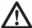
natural_image
Technical line drawing of two interlocking gears with no text or symbolsnatural_image
Diagram of a geological cross-section showing layered strata with triangular patterns (no text or labels)natural_image
Circular mechanical gear diagram with evenly spaced teeth and central bore (no text or symbols)

natural_image
Simple black cross symbol with zigzag lines and a small circle below, no text or symbols present.natural_image
Diagram of a mechanical component with two circular parts and directional arrows indicating motion (no text or symbols)natural_image
Diagram showing a mechanical component and a circular object with directional arrows, no text or symbols present.Rebond rotationnel
Rebond de grimpée
Rebond de pincement
natural_image
Diagram of a medical procedure with a surgical instrument and X-shaped cross symbol (no text or labels)natural_image
Simple line drawing of a 3D object and a circular diagram with a downward arrow (no text or symbols)
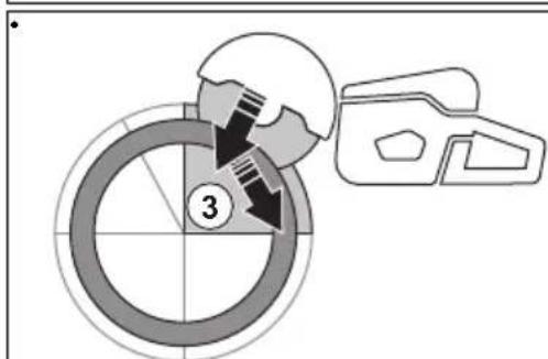
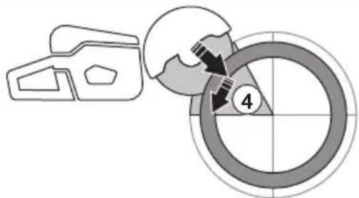

natural_image
Symbolic illustration of crossed-out black X-shape over a gray rectangular block, with arrows indicating downward motion (no text or symbols)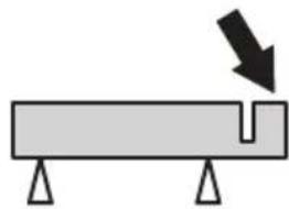
natural_image
Simple diagram of a beam with supports and a downward arrow indicating force or direction (no text or symbols)natural_image
Line drawing of a hand holding a device with a belt, no text or symbols presentnatural_image
Simple line drawing of a mechanical component with an arrow indicating force or motion (no text or symbols)natural_image
Line drawing of a person using a handheld tool on their hands (no text or symbols)natural_image
Technical line drawing of a mechanical assembly with no visible text or symbolsnatural_image
Technical diagram of a mechanical assembly with an inset showing a close-up of a component being inserted (no text or symbols present)Coupe à l'eau

natural_image
Technical line drawing of a mechanical device with a gear and base component, no visible text or symbolsnatural_image
Line drawing of a hand inserting a component into a vehicle chassis (no text or symbols)natural_image
Simple line drawing of a car's side profile with arrows indicating movement or force (no text or symbols)Arrêt du produit
natural_image
Simple line drawing of a car's side panel with a black arrow indicating the left side (no text or symbols)natural_image
Illustration of hands installing or adjusting a mechanical component with arrows indicating assembly (no text or symbols present)
natural_image
Technical line drawing of two mechanical components with arrows indicating assembly or movement (no text or symbols)natural_image
Diagram of a device with a lock and two buttons (no text or symbols)Installation de la fixation de rail RA 10, RA 10S

natural_image
Mechanical clamp assembly diagram showing a lever mechanism with no text or symbolsnatural_image
Technical line drawing of a mechanical tool and a circular component (no text or symbols)natural_image
Mechanical clamp device with directional arrow indicating movement (no text or symbols)natural_image
Simple line drawing of a mechanical clamp or clamping device with no text or symbolsnatural_image
Technical illustration of a mechanical clamp device and a wheel assembly (no text or symbols)natural_image
Technical line drawing of a mechanical device with a circular component and directional arrow (no text or symbols)natural_image
Technical line drawing of a mechanical device with directional arrows indicating movement or force (no text or symbols)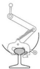
natural_image
Mechanical diagram showing a linkage mechanism with no text or symbols- Découpez le rail.
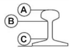
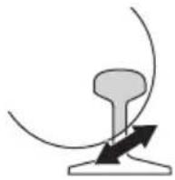
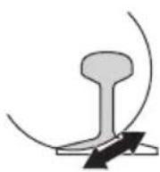

natural_image
Mechanical diagram showing a hand operating a clamping device on a workbench (no text or symbols visible)natural_image
Three abstract line drawings showing different mechanical or structural configurations (no text or symbols)natural_image
Technical line drawing of a mechanical device with two views showing internal components and directional arrows (no text or symbols)- Découpez le rail.

natural_image
Illustration of a hand operating a mechanical device on a platform, no text or symbols presentnatural_image
Three abstract diagrams showing different mechanical or structural configurations, with no visible text or symbols.natural_image
Simple line drawing of a vehicle or road with directional arrows indicating movement (no text or symbols)natural_image
Simple line drawing of a mechanical part with an arrow pointing to a tip (no text or symbols)natural_image
Simple line drawing of a vehicle's front view with a black arrow pointing to the side panel (no text or symbols)natural_image
Simple line drawing of a car front view with a black arrow pointing to the side panel (no text or symbols)natural_image
Technical line drawing of a mechanical assembly (no text or symbols visible)natural_image
Mechanical assembly diagram showing a brake system with springs and levers, no text or symbols presentnatural_image
Mechanical assembly diagram showing a belt drive mechanism with no visible text or symbolsnatural_image
Mechanical assembly diagram showing a belt drive mechanism with springs and gears (no text or labels)natural_image
Technical line drawing of a mechanical component with threaded end and shaft (no text or symbols)natural_image
Technical illustration of a mechanical assembly with a saw cutting tool and a foot pusher (no text or symbols)Kit de roues
natural_image
Mechanical assembly diagram showing a lever mechanism with two springs and a shaft (no text or labels)Entretien
Husqvarna AB, division Construction
Responsable de la documentation technique

Marques déposées
WAARSCHUWING: Lees alle
WAARSCHUWING: Lees alle
natural_image
Two workers performing safety crossing tasks: one using a ladder and the other holding a bulb (no text or symbols)natural_image
Illustration of a person wearing full protective gear and a first aid kit (no text or symbols)natural_image
Simple line drawing of a 3D object with an arrow pointing to a circular shape (no text or symbols)natural_image
Illustration of four different types of screwdrivers, shown from different angles (no text or symbols present)Trillingsdempingssysteem controleren

natural_image
Technical line drawing of two interlocking gears with no text or symbolsnatural_image
Diagram of a geological cross-section showing layered strata with directional arrows indicating flow or force (no text or labels)natural_image
Circular mechanical component diagram with evenly spaced teeth and central bore (no text or symbols)

natural_image
Abstract black X-shaped line with zigzag arcs and a small circle below (no text or symbols)natural_image
Diagram of a medical device with two circular components and directional arrows indicating movement or force (no text or symbols)natural_image
Technical line drawing of a mechanical assembly with no visible text or symbolsnatural_image
Technical line drawing of a mechanical assembly with two arrows indicating directional components (no text or symbols present)Werking
Inleiding

natural_image
Diagram showing a mechanical component and a circular object with directional arrows, no text or symbols present.Roterende terugslag
natural_image
Diagram of a medical device with a cross symbol crossed over a table, no text or labels presentnatural_image
Simple line drawing of a device with a magnified circular section showing a download icon (no text or symbols)
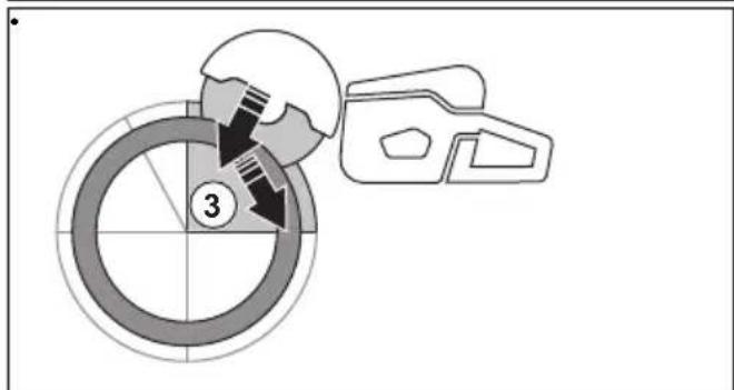

natural_image
Two diagrams showing a cross-shaped object with arrows indicating direction, next to a rectangular object with a notch and base supports (no text or symbols)natural_image
Line drawing of a hand holding a device with a bag, no text or symbols presentnatural_image
Simple line drawing of a mechanical component interacting with a sphere, no text or symbols presentnatural_image
Line drawing of a person using a handheld device to lift or stand (no text or symbols)natural_image
Technical line drawing of a mechanical assembly with no visible text or symbolsnatural_image
Technical diagram of a mechanical assembly with labeled parts and an inset showing a disassembly or assembly process (no text or symbols present)Nat zagen

natural_image
Technical line drawing of a mechanical device with a base unit and a magnified inset showing internal components (no text or symbols)natural_image
Line drawing of a hand inserting a plastic component into a vehicle chassis (no text or symbols)natural_image
Simple line drawing of a mechanical component with two arrows indicating direction (no text or symbols)Product stoppen
natural_image
Simple line drawing of a car's side panel with a black arrow pointing to the front portion (no text or symbols)natural_image
Illustration of hands installing or adjusting a mechanical component with arrows indicating assembly (no text or symbols present)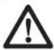
Installatiepunten en railbevestigingsindicator
natural_image
Diagram showing two mechanical components with arrows indicating motion or assembly, no text or symbols presentnatural_image
Diagram of a device control panel with an arrow pointing to a lock and two buttons (no text or symbols)De railbevestiging installeren RA 10, RA 10S

natural_image
Mechanical clamp assembly diagram showing a lever mechanism with arrows indicating motion (no text or symbols)natural_image
Technical line drawing of a mechanical device with a circular component and lever mechanism (no text or symbols)natural_image
Mechanical clamp device with lever mechanism and directional arrow (no text or symbols)natural_image
Mechanical clamp device with spring and lever mechanism (no text or symbols)natural_image
Mechanical assembly diagram showing a clamp mechanism and a hand operating a wheel (no text or symbols present)natural_image
Technical line drawing of a mechanical device with a circular component and directional arrow (no text or symbols)natural_image
Technical line drawing of a mechanical device with two views showing internal components (no text or symbols)- De rail doorzagen.
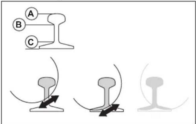
natural_image
Technical line drawing of a mechanical clamp or clamping device with a circular component on top (no text or symbols)e) Draai de 2 schroeven (A) vast.
natural_image
Three abstract line drawings of mechanical components or connectors, no text or symbols presentnatural_image
Technical line drawing of a mechanical device with two views showing different configurations (no text or symbols)- De rail doorzagen.

natural_image
Illustration of a hand operating a mechanical clamp or tool on a workbench (no text or symbols visible)natural_image
Three abstract line drawings of mechanical components or connectors, no text or symbols presentnatural_image
Simple line drawing of a car with two arrows indicating direction (no text or symbols)natural_image
Simple line drawing of a mechanical part with an arrow indicating direction (no text or symbols)natural_image
Simple line drawing of a vehicle or car with an arrow indicating direction (no text or symbols)natural_image
Simple line drawing of a device with an arrow pointing to a component (no text or symbols)natural_image
Technical line drawing of a mechanical assembly with no visible text or symbolsnatural_image
Mechanical assembly diagram showing a chain of springs and levers with no visible text or symbolsnatural_image
Mechanical assembly diagram showing a belt drive mechanism with a close-up inset of the component (no text or symbols)natural_image
Mechanical assembly diagram showing a belt drive mechanism with no visible text or symbolsnatural_image
Technical line drawing of a mechanical component with threaded end and shaft (no text or symbols)natural_image
Technical illustration of a mechanical assembly with a saw cutting tool and a foot pusher (no text or symbols)Wielenset
natural_image
Mechanical assembly diagram showing two connected components with directional arrows indicating motion (no text or labels)Service
Goedgekeurd servicecentrum
Original instructions
Originalanweisungen