
460 R - Saw HUSQVARNA - Free user manual and instructions
Find the device manual for free 460 R HUSQVARNA in PDF.


| Product Type | Gasoline-Powered Chainsaw |
| Brand | Husqvarna |
| Model | 460 R |
| Engine Displacement | 60.3 cc |
| Power Output | 3.2 kW |
| Weight (without bar/chain) | 6.3 kg |
| Recommended Bar Length | 20 in (50 cm) |
| Chain Pitch | 0.325 in |
| Chain Gauge | 0.058 in |
| Fuel Tank Capacity | 0.6 L |
| Oil Tank Capacity | 0.3 L |
| Idle Speed | 2700 rpm |
| Max Power Speed | 9000 rpm |
| Ignition System | Electronic |
| Carburetor | Walbro |
| Air Filtration System | Centrifugal |
| Vibration Damping | LowVib |
| Safety Features | Chain brake, throttle interlock, hand guard |
| Maintenance | Air filter cleaning, spark plug, bar oil |
| Repairability | Spare parts available; authorized service centers |
Frequently Asked Questions - 460 R HUSQVARNA
User questions about 460 R HUSQVARNA
0 question about this device. Answer the ones you know or ask your own.
Ask a new question about this device
Download the instructions for your Saw in PDF format for free! Find your manual 460 R - HUSQVARNA and take your electronic device back in hand. On this page are published all the documents necessary for the use of your device. 460 R by HUSQVARNA.
USER MANUAL 460 R HUSQVARNA
Transportation and storage....35
Technical data.... 35
Accessories.... 36
EC Declaration of Conformity.... 39
Introduction
Intended use
This product is intended for sawing in wood.
Note: National regulations can set limit to the operation of the product.
Product description
The Husqvarna 455 Rancher, 455e Rancher, 460 Rancher are chainsaw models with a combustion engine.
Work is constantly in progress to increase your safety and efficiency during operation. Speak to your servicing dealer for more information.
Product overview
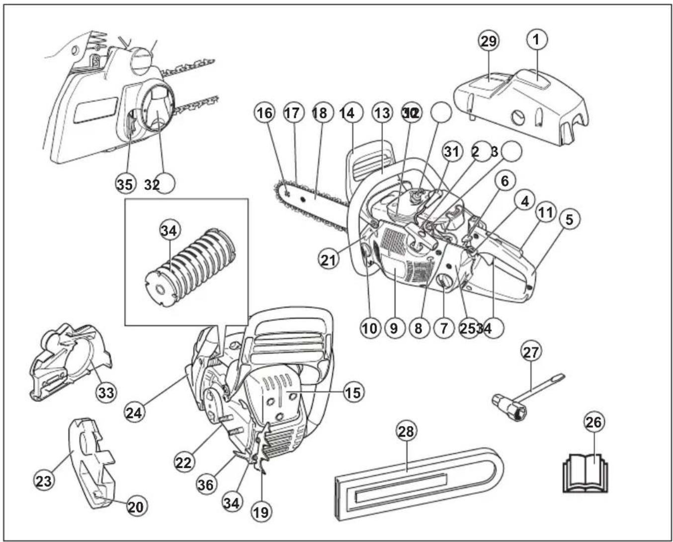
-
Cylinder cover 2. Starter rope handle
-
Air purge
-
Choke control
-
Rear handle
-
Start/stop switch
-
Fuel tank
-
Adjuster screws carburetor
-
Starter housing
-
Chain oil tank
-
Throttle trigger lockout
-
Decompression valve
-
Front handle
-
Chain brake and front hand guard
-
Muffler
-
Bar tip sprocket
-
Saw chain
-
Guide bar
-
Spiked bumper
-
Chain tensioning screw
-
Product and serial number plate
-
Oil pump adjustment screw
-
Clutch cover
-
Right hand guard
-
Throttle trigger
-
Operator's manual
-
Combination wrench
-
Transportation guard
-
Information and warning decal
-
Spark plug
-
Spark plug cap
-
Knob (455e Rancher)
-
Brake band
-
Vibration damping system, 3 units
-
Chain tensioning wheel (455e Rancher)
-
Chain catcher
Symbols on the product

Be careful and use the product correctly. This product can cause serious injury or death to the operator or others.

Read the operator's manual carefully and make sure that you understand the instructions before you use this product.

Always wear approved protective helmet, approved hearing protection and eye protection.

This product complies with applicable EC Directives.

Noise emission to the environment complies with applicable EC Directives. The noise emission of the product is specified in Technical data on page 35 and on the label.

Chain brake, engaged (right). Chain brake, disengaged (left).
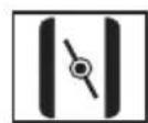
Choke.

Decompression valve.

Air purge bulb.

Adjustment of the oil pump.

Fuel.

Chain oil.
yyyyMMddxxxx The rating plate shows se-
rial number. yyyy is the production year and ww is the production week.
Note: Other symbols/decals on the product refer to certification requirements for some markets.
EU V

WARNING: Tampering with the engine voids the EU type-approval of this product.
Safety
Safety definitions
Warnings, cautions and notes are used to point out specially important parts of the manual.

WARNING: Used if there is a risk of injury or death for the operator or bystanders if the instructions in the manual are not obeyed.

CAUTION: Used if there is a risk of damage to the product, other materials or the adjacent area if the instructions in the manual are not obeyed.
Note: Used to give more information that is necessary in a given situation.
General safety instructions

WARNING: Read the warning instructions that follow before you use the product.
- A chainsaw is a dangerous tool if used carelessly or incorrectly and can cause serious injury or death. It is very important that you read and understand the contents of this operator's manual.
- Under no circumstances may the design of the product be modified without the permission of the manufacturer. Do not use a product that appears to have been modified by others and only use accessories recommended for this product. Non-authorized modifications and/or accessories can result in serious personal injury or the death of the operator or others.
- The inside of the muffler contain chemicals that may be carcinogenic. Avoid contact with these elements in the event of a damaged muffler.
- Long term inhalation of the engine's exhaust fumes, chain oil mist and sawdust can represent a health risk.
- This product produces an electromagnetic field during operation. This field may under some circumstances interfere with active or passive medical implants. To reduce the risk of serious or fatal injury, we recommend persons with medical implants to consult their physician and the medical implant manufacturer before operating this product.
- The information in this operator's manual is never a substitute for professional skills and experience. If you get into a situation where you feel unsafe, stop and seek expert advice. Contact your servicing dealer or an experienced chainsaw user. Do not attempt any task that you feel unsure of!
Safety instructions for operation

WARNING: Read the warning instructions that follow before you use the product.
- Before using the product you must understand the effects of kickback and how to avoid them. Refer to Kickback information on page 12 for instructions.
- Never use a product that is faulty.
- Never use a product with visible damage to the spark plug cap and ignition cable. A risk of sparking arises, which can cause a fire.
- Never use the product if you are fatigued, while under the influence of alcohol or drugs, medication or anything that could affect your vision, alertness, coordination or judgement.
- Do not use the product in bad weather such as dense fog, heavy rain, strong wind, intense cold, etcetera. Working in bad weather is tiring and often brings added risks, such as icy ground, unpredictable felling direction, etcetera.
- Never start a product unless the guide bar, saw chain and all covers are fitted correctly. Refer to Assembly on page 9 for instructions. Without a bar and saw chain attached to the product the clutch can come loose and cause serious injury.

- Never start the product indoors. Exhaust fumes can be dangerous if inhaled.
- The exhaust fumes from the engine are hot and can contain sparks, which can start a fire. Never start the product near flammable material!
- Observe your surroundings and make sure that there is no risk of people or animals coming in contact with or affect your control of the product.
- Never allow children to use or be in the vicinity of the product. As the product is equipped with a spring-loaded start/stop switch and can be started by low speed and force on the starter handle, even small children under some circumstances can produce the force necessary to start the product. This can mean a risk of serious personal injury. Therefore remove the spark plug cap when the product is not under close supervision.
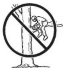
- You must have a steady stance in order to have full control of the product. Never work standing on a
ladder, in a tree or where you do not have a firm ground to stand on.

natural_image
Prohibition sign showing a worker on a ladder crossed out by a diagonal line, no text or symbols present.- Lack of concentration can lead to kickback if the kickback zone of the bar accidentally touches a branch, nearby tree or some other object.
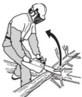
natural_image
Illustration of a person using a saw to cut wood, showing mechanical components and motion direction (no text or symbols)- Never use the product by holding it with one hand. This product is not safely controlled with one hand.
• Always hold the product with both hands. The right hand should be on the rear handle, and the left hand on the front handle. All people, whether right or left handed, should use this grip. Use a firm grip with thumbs and fingers encircling the handles. This grip minimizes the risk of kickback and lets you keep the product under control. Do not let go of the handles!

natural_image
Simple line drawing of a mechanical device with two hands operating it (no text or symbols)- Never use the product above shoulder height.

- Do not use the product in a situation where you cannot call for help in case of an accident.
- Before moving your product, switch off the engine and lock the saw chain using the chain brake. Carry the product with the guide bar and saw chain
pointing backwards. Fit a transportation guard to the guide bar before transporting the product or carrying it for any distance.
- When you put the product on the ground, lock the saw chain using the chain brake and ensure you have a constant view of the product. Switch the engine off before leaving your product for any length of time.
• Sometimes chips get stuck in the clutch cover causing the saw chain to jam. Always stop the engine before cleaning.
- Running an engine in a confined or badly ventilated area can result in death due to carbon monoxide poisoning.
- The exhaust fumes from the engine are hot and may contain sparks which can start a fire. Do not start the product indoors or near flammable material.
- Use the chain brake as a parking brake when you start the product and when you move short distances. Always carry the product in the front handle. This decreases the risk that you or a person near you get hit by the saw chain.
• Overexposure to vibration can lead to circulatory damage or nerve damage in people who have impaired circulation. Contact your doctor if you experience symptoms of overexposure to vibration. Such symptoms include numbness, loss of feeling, tingling, pricking, pain, loss of strength, changes in skin colour or condition. These symptoms normally appear in the fingers, hands or wrists. These symptoms may be increased in cold temperatures.
- It is not possible to cover every conceivable situation you can face when using this product. Always exercise care and use your common sense. Avoid all situations which you consider to be beyond your capability. If you still feel uncertain about operating procedures after reading these instructions, you should consult an expert before continuing. Do not hesitate to contact your dealer or Husqvarna if you have any questions about the use of the product. We will willingly be of service and provide you with advice as well as help you to use your product both efficiently and safely. Attend a training course in chainsaw usage if possible. Your dealer, forestry school or your library can provide information about which training materials and courses are available.
Personal protective equipment

WARNING: Read the warning instructions that follow before you use the product.
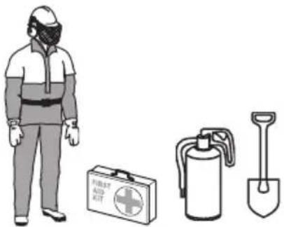
- Most chainsaw accidents occur when the saw chain touches the operator. You must use approved personal protective equipment during operation. Personal protective equipment does not give you full protection from injuries but it decreases the degree of injury if an accident occurs. Speak to your servicing dealer for recommendations about which equipment to use.
- Your clothing must be close-fitting but not limit your movements. Regularly do a check of the condition of the personal protective equipment.
- Use an approved protective helmet.
- Use approved hearing protection. Long-term exposure to noise can result in permanent damage to the hearing.
- Use protective glasses or a face visor to decrease the risk of injury from thrown objects. The product can throw objects, such as wood chips, small pieces of wood and more, at large force. This can result in serious injury, especially to the eyes.
- Use gloves with saw protection.
- Use pants with saw protection.
- Use boots with saw protection, steel toe-cap and non-slip sole.
• Always have a first-aid kit with you. - Risk of sparks. Keep fire extinguishing tools and a shovel near to prevent forest fires.
Safety devices on the product

WARNING: Read the warning instructions that follow before you use the product.
- Do not use a product with defective safety devices.
- Do a check of the safety devices regularly. Refer to Maintenance and checks of the safety devices on the product on page 22.
- If the safety devices are defective, speak to your Husqvarna servicing dealer.
Chain brake and front hand guard
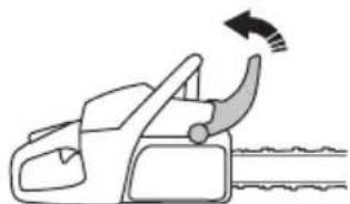
Your product has a chain brake that stops the saw chain if you get a kickback. The chain brake decreases the risk of accidents, but only you can prevent them.
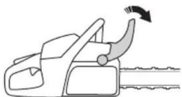
The chain brake engages (A) manually by your left hand or automatically by the inertia release mechanism. Push the front hand guard (B) forward to engage the chain brake manually.

Pull the front hand guard rearward to disengage the chain brake.
natural_image
Line drawing of a car handle with an arrow indicating airflow direction (no text or symbols)Throttle trigger lockout
The throttle trigger lockout prevents accidental operation of the throttle trigger. If you put your hand around the handle and press the throttle trigger lockout (A), it releases the throttle trigger (B). If you release the handle, the throttle trigger and the throttle trigger lockout move back to their initial positions. This function locks the throttle trigger at idle speed.

natural_image
Diagram of a chain-linking device with labeled parts A and B (no text or symbols beyond labels)Chain catcher
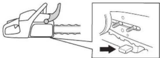
The chain catcher catches the saw chain if it breaks or comes loose. Correct saw chain tension and correctly
applied maintenance on the saw chain and guide bar, decrease the risk of accidents.
natural_image
Diagram showing a chain saw cutting down a car's blade, with an arrow indicating the process (no text or symbols present)Right hand guard
The right hand guard is a protection for your hand on the rear handle. The right hand guard gives you protection if the saw chain breaks or derails. The right hand guard also gives you protection from branches or twigs.

natural_image
Technical line drawing of a mechanical component or bracket (no text or symbols)Vibration damping system
The vibration damping system decreases vibration in the handles. Vibration damping units operate as a separation between the product body and the handle unit.
Refer to Product overview on page 2 for information about where the vibration damping system is on your product.
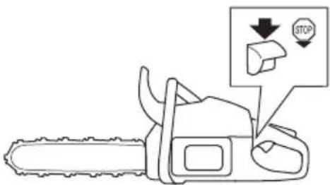
Start/stop switch
Use the start/stop switch to stop the engine.
Muffler

WARNING: The muffler becomes very hot during/after operation and at idle speed. There is a risk of fire, especially when you operate the product near flammable materials and/or fumes.

WARNING: Do not operate a product without a muffler or with a defective muffler. A defective muffler can increase the noise level and the risk of fire. Keep fire extinguishing tools near. Do not use a product without, or with a broken, spark arrestor mesh if you must have a spark arrestor mesh in your area.
The muffler keeps the noise levels to a minimum and points the exhaust fumes away from the operator. In areas with a hot, dry weather there is a high risk of fire. Obey local regulations and maintenance instructions.

natural_image
Line drawing of a portable electronic device with ports and buttons (no text or symbols)Fuel safety

WARNING: Read the warning instructions that follow before you use the product.
• Make sure there is plenty of ventilation when refuelling or mixing fuel (petrol and two-stroke oil).
- Fuel and fuel vapour are highly flammable and can cause serious injury when inhaled or allowed to come in contact with the skin. For this reason observe caution when handling fuel and make sure there is adequate ventilation.
• Take care when handling fuel and chain oil. Be aware of the risks of fire, explosion and those associated with inhalation.
- Do not smoke and do not place any hot objects in the vicinity of fuel.
• Always stop the engine and let it cool for a few minutes before refuelling.
- When refuelling, open the fuel cap slowly so that any excess pressure is released gently.
- Tighten the fuel cap carefully after refuelling.
- Never refuel the machine while the engine is running.
• Always move the product at least 3 m (10 ft) away from the refuelling area and fuel source before starting.

After refuelling, there are some situations where you must never start the product:
- If you have spilled fuel or chain oil on the product. Wipe off the spillage and allow remaining fuel to evaporate.
- If you have spilled fuel on yourself or on your clothes. Change your clothes and wash any part of your body that has come in contact with fuel. Use soap and water.
- If the product leaks fuel. Regularly do a check for leaks from the fuel tank, fuel cap and fuel lines.
Safety instructions for maintenance

WARNING: Read the warning instructions that follow before you do maintenance on the product.
- Do only the maintenance and servicing given in this operator's manual. Let professional servicing personnel do all other servicing and repairs.
- Regularly do the safety checks, maintenance and service instructions given in this manual. Regular maintenance increases the life of the product and decreases the risk of accidents. Refer to Maintenance on page 21 for instructions.
- If the safety checks in this operator's manual is not approved after you do maintenance, speak to your servicing dealer. We guarantee that there are professional repairs and servicing available for your product.
Safety instructions for the cutting equipment

WARNING: Read the warning instructions that follow before you use the product.
- Only use the guide bar/saw chain combinations and filing equipment that we recommend. Refer to Accessories on page 36 for instructions.
- Use protective gloves when you use or do maintenance on the saw chain. A saw chain that does not move can also cause injuries.
- Keep the cutting teeth correctly sharpened. Obey the instructions and use the recommended file gauge. A saw chain that is damaged or incorrectly sharpened increases the risk of accidents.

natural_image
Simple line drawing of a mechanical component with a starburst effect (no text or symbols)- Keep the correct depth gauge setting. Obey the instructions and use the recommended depth gauge setting. Too large depth gauge setting increases the risk of kickback.

natural_image
Pure technical line drawing of a mechanical part with no text or symbols• Make sure that the saw chain has the correct tension. If the saw chain is not tight against the guide bar, the saw chain can derail. An incorrect saw chain tension increases wear on the guide bar, saw chain and chain drive sprocket. Refer to To adjust the tension of the saw chain (455 Rancher, 460 Rancher) on page 29.

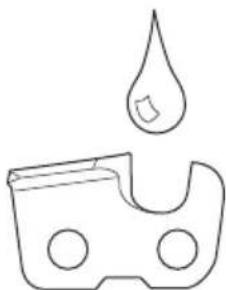
- Do maintenance on the cutting equipment regularly and keep it correctly lubricated. If the saw chain is not correctly lubricated, the risk of wear on the guide bar, saw chain and chain drive sprocket increases.
natural_image
Simple line drawing of a droplet falling from a container (no text or symbols)Assembly
Introduction

WARNING: Read and understand the safety chapter before you assemble the product.
To assemble the guide bar and saw chain (455 Rancher, 460 Rancher)
- Move the front hand guard rearward to disengage the chain brake.
- Remove the bar nuts and the clutch cover.

natural_image
Technical line drawing of a mechanical device with labeled parts (no readable text or symbols)Note: If the clutch cover is not easy to remove, tighten the bar nut, engage the chain brake and release. A click is heard if it is released correctly.
- Assemble the guide bar onto the bar bolts. Move the guide bar to its most rear position.
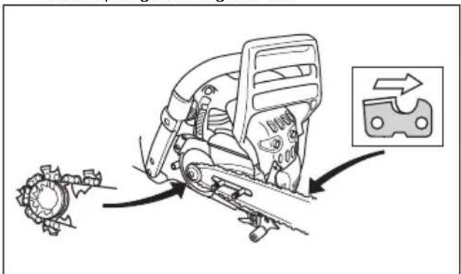
- Install the saw chain correctly around the drive sprocket and put it in the groove on the guide bar.

WARNING: Always use protective gloves when you assemble the saw chain.
- Make sure that the edges of the cutters point forward on the top edge of the guide bar.
-
Align the hole in the guide bar with the chain adjuster pin and install the clutch cover.
-
Tighten the bar nuts finger tight.
- Tighten the saw chain. Refer to To adjust the tension of the saw chain (455 Rancher, 460 Rancher) on page 29 for instructions.
- Tighten the bar nuts.
Note: Some models have only 1 bar nut.
To assemble the guide bar and saw chain (455e Rancher)
- Move the front hand guard rearward to disengage the chain brake.
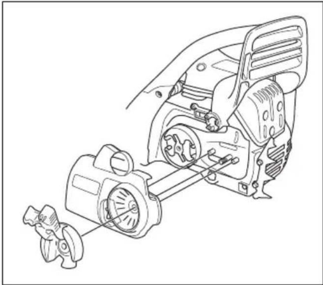
- Remove the knob and the clutch cover.
natural_image
Technical line drawing of a mechanical assembly with gears and housing (no text or symbols)Note: If the clutch cover is not easy to remove, tighten the bar nut, engage the chain brake and release. A click is heard if it is released correctly.
- Assemble the guide bar onto the bar bolts. Move the guide bar to its most rear position.
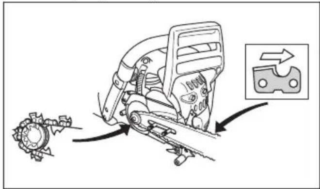
- Install the saw chain correctly around the drive sprocket and put it in the groove on the guide bar.

WARNING: Always use protective gloves when you assemble the saw chain.
- Make sure that the edges of the cutters point forward on the top edge of the guide bar.
natural_image
Mechanical assembly diagram showing gear and motor components with directional arrows indicating motion (no text or symbols)-
Align the hole in the guide bar with the chain adjuster pin and install the clutch cover.
-
Tighten the bar nuts finger tight.
-
Tighten the saw chain. Refer to To adjust the tension of the saw chain (455e Rancher) on page 30 for instructions.
-
Tighten the bar nuts.
Operation
Introduction

WARNING: Read and understand the safety chapter before you use the product.
To do a function check before you use the product
- Make sure that the chain brake operates correctly and that it is not damaged.
- Make sure that the right hand guard is not damaged.
- Make sure that the throttle lockout operates correctly and that it is not damaged.
- Make sure that the start/stop switch operates correctly and that it is not damaged.
- Make sure that there is no oil on the handles.
- Make sure that the vibration damping system operates correctly and that it is not damaged.
- Make sure that the muffler is correctly attached and that it is not damaged.
- Make sure that all parts of the product are correctly attached and not damaged or missing.
- Make sure that the chain catcher is correctly attached.
- Do a check of the saw chain tension.

Fuel
This product has a two-stroke engine.

CAUTION: Incorrect type of fuel can result in engine damage. Use a mixture of gasoline and two-stroke oil.
Premixed fuel
- Use Husqvarna premixed alkylate fuel of a good quality, for best performance and extension of the engine life. This fuel contains less harmful chemicals compared to regular fuel, which decreases harmful exhaust fumes. The quantity of remains after combustion is lower with this fuel, which keeps the components of the engine more clean.
To mix fuel
Gasoline
- Use good quality unleaded gasoline with a maximum of 10% ethanol contents.

CAUTION: Do not use gasoline with an octane grade less than 90 RON/87 AKI. Use of a lower octane grade can cause engine knocking, which causes engine damages.
• We recommend that you use gasoline of a higher octane grade for work with continuously high rpm.
Two-stroke oil
- For best results and performance use Husqvarna two-stroke oil.
- If Husqvarna two-stroke oil is not available, use a two-stroke oil of good quality for air-cooled engines. Speak to your servicing dealer to select the correct oil.

CAUTION: Do not use two-stroke oil for water-cooled outboard engines, also referred to as outboard oil. Do not use oil for four-stroke engines.
To mix gasoline and two-stroke oil
| Gasoline, liter Two-stroke | oil, liter |
| 2% (50:1) | |
| 5 0.10 | |
| 10 0.20 | |
| 15 0.30 | |
| 20 0.40 |

CAUTION: Small errors can influence the ratio of the mixture drastically when you mix small quantities of fuel. Measure the quantity of oil carefully and make sure that you get the correct mixture.
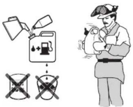
- Fill half the quantity of gasoline in a clean container for fuel.
- Add the full quantity of oil.
- Shake the fuel mixture.
- Add the remaining quantity of gasoline to the container.
- Carefully shake the fuel mixture.

CAUTION: Do not mix fuel for more than 1 month at a time.
To fill the fuel tank
- Clean the area around the fuel tank cap.

natural_image
Simple black icon showing a droplet and a gas pump with a plus sign, symbolizing fuel or energy addition (no text or symbols)-
Shake the container and make sure that the fuel is fully mixed.
-
Tighten the fuel tank cap carefully.
- Move the product 3 m/10 ft or more away from the refueling area and fuel source before starting.
Note: To see where the fuel tank is on you product, refer to Product overview on page 2.
To do a run-in
- During the first 10 hours of operation, do not apply full throttle without load for extended periods.
To use the correct chain oil

WARNING: Do not use waste oil, which can cause injury to you and the environment. Waste oil also causes damage to the oil pump, the guide bar and the saw chain.

WARNING: The saw chain can break if the lubrication of the cutting equipment is not sufficient. Risk of serious injury or death to the operator.

WARNING: This product has a function that lets the fuel run out before the chain oil. Use the correct chain oil for this function to operate correctly. Speak to your servicing dealer when you select your chain oil.
Note: This product has an automatic chain lubrication system. You can also adjust the oil flow. Refer to To adjust the chain oil flow on page 32.
- Use Husqvarna chain oil for maximum saw chain life and to prevent negative effects on the environment. If Husqvarna chain oil is not available, we recommend you to use a standard chain oil.
- Use a chain oil with good adherence to the saw chain.
- Use a chain oil with correct viscosity range that agrees with the air temperature.

CAUTION: If the oil is too thin, it runs out before the fuel. In temperatures below 0^ C/ 32^ F some chain oils become too thick, which can cause damage to the oil pump components.
- Use the recommended cutting equipment. Refer to Accessories on page 36.
- Remove the cap to the chain oil tank.
- Fill the chain oil tank with chain oil.
- Attach the cap carefully.

natural_image
Abstract black-and-white graphic with droplet and mask-like shapes (no text or symbols)Note: To see where the chain oil tank is on you product, refer to Product overview on page 2.
Kickback information

WARNING: A kickback can cause serious injury or death to the operator or others. To decrease the risk you must know the causes of kickback and how to prevent them.
A kickback occurs when the kickback zone of the guide bar touches an object. A kickback can occur suddenly and with large force, which throws the product in the direction of the operator.

Kickback always occurs in the cutting plane of the guide bar. Usually, the product is thrown against the operator but can also move in a different direction. It is how you use the product when the kickback occurs that causes the direction of the movement.

natural_image
Illustration of a person in protective gear using a tool to lift a cylindrical object with an arrow indicating motion (no text or symbols)A smaller bar tip radius decreases the force of the kickback.
Use a low kickback saw chain to decrease the effects of kickback. Do not let the kickback zone touch an object.

WARNING: No saw chain fully prevents kickback. Always obey the instructions.
Common questions about kickback
- Will the hand always engage the chain brake during a kickback?
No. It is necessary to use some force to push the front hand guard forward. If you do not use the force necessary, the chain brake will not be engaged. You must also hold the handles of the product stable with two hands during work. If a kickback occurs, it is possible that the chain brake does not stop the saw chain before it touches you. There are also some positions in which your hand can not touch the front hand guard to engage the chain brake. An example of this is in the felling position.
- Will the inertia release mechanism always engage the chain brake during kickback?
No. First, the chain brake must operate correctly. Refer to To do a check of the chain brake on page 23 for instructions about how to do a check of the chain brake. We recommend you to do this each time before you use the product. Second, the force of the kickback must be large to engage the chain brake. If the chain brake is too sensitive, it can engage during rough operation.
- Will the chain brake always protect me from injury during a kickback?
No. The chain brake must operate correctly to give protection. The chain brake must also be engaged during a kickback to stop the saw chain. If you are near the guide bar, it is possible that the chain brake does not have time to stop the saw chain before it hits you.

WARNING: Only you and the correct working technique can prevent kickbacks.
To start the product
To prepare to start with a cold engine

WARNING: The chain brake must be engaged when the product is started to decrease the risk of injury.
- Move the front hand guard forward to engage the chain brake.
natural_image
Diagram of a manual tool with a curved arrow indicating rotation or motion (no text or symbols)-
Pull the choke control (A) out to set it in choke position.
-
Push the air purge bulb (B) approximately 6 times or until fuel starts to fill the bulb. It is not necessary to fill the air purge bulb fully.
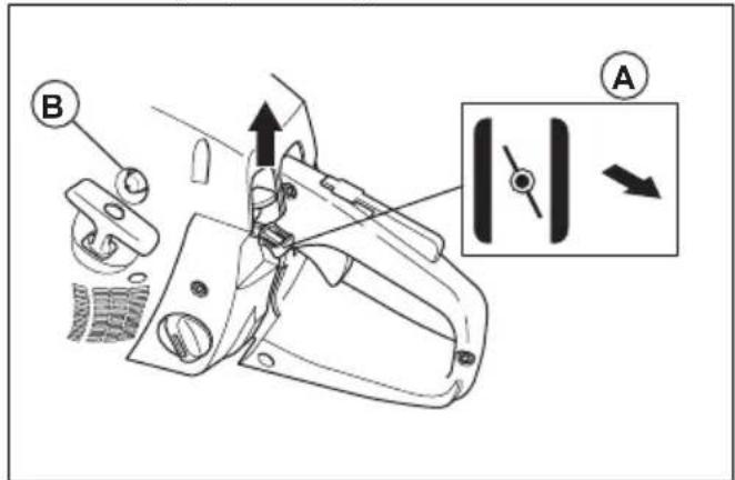
- Push the decompression valve (C).

- Continue to To start the product on page 13 for more instructions.
To prepare to start with a warm engine

WARNING: The chain brake must be engaged when the product is started to decrease the risk of injury.
- Move the front hand guard forward to engage the chain brake.

natural_image
Line drawing of a manual chain attachment mechanism with motion arrow (no text or symbols)-
Pull the choke control out and then push the choke control in again.
-
Pull the start/stop switch up.
-
Push the air purge bulb approximately 6 times or until fuel starts to fill the bulb. It is not necessary to fill the air purge bulb fully.

- Push the decompression valve.

natural_image
Line drawing of a car seatbelt with a magnified inset showing a circular component (no text or symbols)- Continue to To start the product on page 13 for more instructions.
To start the product

WARNING: You must keep your feet in a stable position when you start the product.

WARNING: If the saw chain rotates at idle speed, speak to your servicing dealer and do not use the product.
- Put the product on the ground.
- Put your left hand on the front handle.
- Put your right foot into the footgrip on the rear handle.
- Pull the starter rope handle slowly with your right hand until you feel resistance.

WARNING: Do not twist the starter rope around your hand.
- Pull the starter rope handle quickly and with force.

natural_image
Illustration of a person using a chainsaw to cut the chain (no text or symbols present)
CAUTION: Do not pull the starter rope to full extension and do not let go of the starter rope handle. This can cause damage to the product.
a) If you start your product with a cold engine, pull the starter rope handle until the engine fires.
Note: You can identify when the engine fires through a "puff" sound.
b) Disengage the choke.
-
Pull the starter rope handle until the engine starts.
-
Quickly disengage the throttle trigger lockout to set the product to idle speed.

natural_image
Line drawing of a manual chain-linking device with arrows indicating motion (no text or symbols)- Move the front hand guard rearward to disengage the chain brake.

natural_image
Line drawing of a car hood with airflow direction arrow (no text or symbols)- Use the product.
To stop the product
- Push the start/stop switch down to stop the engine.

Pull stroke and push stroke
You can cut through wood with the product in 2 different positions.
• To cut on the pull stroke is when you cut with the bottom of the guide bar. The saw chain pulls through the tree when you cut. In this position you have better control of the product and the position of the kickback zone.

natural_image
Line drawing of a hand using a chain mill to cut a circular saw (no text or symbols)• To cut on the push stroke is when you cut with the top of the guide bar. The saw chain pushes the product in the direction of the operator.

natural_image
Line drawing of a manual power saw cutting through a blade, showing motion direction (no text or symbols)
WARNING: If the saw chain is caught in the trunk, the product can be pushed at you. Hold the product tightly and make sure that the kickback zone of the guide bar does not touch the tree and causes a kickback.

To use the cutting technique

WARNING: Use full throttle when you cut and decrease to idle speed after each cut.

CAUTION: Engine damage can occur if the engine runs for too long at full throttle without load.
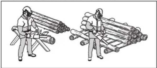
- Put the trunk on a saw horse or runners.
natural_image
Illustration of two workers handling large logs, one wearing a protective gear and the other in a hard hat (no text or symbols)
WARNING: Do not cut trunks in a pile. That increases the risk of kickback and can result in serious injury or death.
- Remove the cut pieces from the cutting area.

WARNING: Cut pieces in the cutting area increase the risk of kickback and that you can not keep your balance.
To cut a trunk on the ground
- Cut through the trunk on the pull stroke. Keep full throttle but be prepared for sudden accidents.


WARNING: Make sure that the saw chain does not touch the ground when you complete the kerf.
- Cut approximately 23 through the trunk and then stop. Turn the trunk and cut from the opposite side.

To cut a trunk that has support on one end

WARNING: Make sure that the trunk does not break during cutting. Obey the instructions below.

natural_image
Illustration of a landslide with a lightning bolt and warning symbol (no text or labels)- Cut on the push stroke approximately 13 through the trunk.
- Cut through the trunk on the pull stroke until the two kerfs touch.

To cut a trunk that has support on two ends

WARNING: Make sure that the saw chain does not get caught in the trunk during cutting. Obey the instructions below.

natural_image
Simple line drawing of a car with warning symbols indicating hazard (no text or labels)-
Cut on the pull stroke approximately 13 through the trunk.
-
Cut through the remaining part of the trunk on the push stroke to complete the cut.
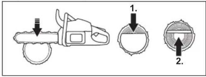

WARNING: Stop the engine if the saw chain gets caught in the trunk. Use a lever to open up the kerf and remove the product. Do not try to pull the product out by hand. This can result in injury when the product suddenly breaks free.
To use the limbing technique
Note: For thick branches, use the cutting technique. Refer to To use the cutting technique on page 15

WARNING: There is a high accident risk when you use the limbing technique. Refer to Kickback information on page 12 for instructions how to prevent kickback.

WARNING: Cut limbs one by one. Be careful when you remove small limbs and do not cut bushes or many small limbs at the same time. Small limbs can get caught in the saw chain and prevent safe operation of the product.
Note: Cut the limbs piece by piece if it is necessary.

- Remove the limbs on the right side of the trunk. a) Keep the guide bar on the right side of the trunk and keep the body of the product against the trunk.
b) Select the applicable cutting technique for the tension in the branch.

natural_image
Illustration of a hand using a tool to cut a car's seat, showing motion and angle (no text or symbols)
WARNING: If you are not sure about how to cut the branch, speak to a professional chainsaw operator before you continue.
- Remove the limbs on the top of the trunk.
a) Keep the product on the trunk and let the guide bar move along the trunk.
b) Cut on the push stroke.

natural_image
Illustration of a hand using a power saw to cut tree bark with a black arrow indicating the process (no text or symbols present)- Remove the limbs on the left side of the trunk.
a) Select the applicable cutting technique for the tension in the branch.

natural_image
Illustration of a hand using a tool to cut tree bark with a black arrow indicating the direction (no text or symbols present)
WARNING: If you are not sure about how to cut the branch, speak to a professional chainsaw operator before you continue.
Refer to To cut trees and branches that are in tension on page 20 for instructions on how to cut branches that are in tension.
To use the tree felling technique

WARNING: You must have experience to fell a tree. If possible, engage in a training course in chainsaw operation. Speak to an operator with experience for more knowledge.
To keep a safe distance
- Make sure that persons around you keep a safe distance at a minimum of 2 1/2 tree lengths.

flowchart
graph TD
    A["Forest"] --> B["Person with Circle"]
    B --> C["Tree"]
    style A fill:#f9f,stroke:#333
    style C fill:#bbf,stroke:#333
- Make sure that no person is in the risk zone before or during felling.

natural_image
Illustration of a person using a tree spray gun to shoot logs in a forest (no text or symbols)To calculate the felling direction
- Examine in which direction it is necessary for the tree to fall. The goal is to fell it in a position where you can limb and cut the trunk easily. It is also important that you are stable on your feet and can move about safely.

WARNING: If it is dangerous or not possible to fell the tree in its natural direction, fell the tree in a different direction.
-
Examine the natural fall direction of the tree. For example the tilt and bend of the tree, wind direction, the location of the branches and weight of snow.
-
Examine if there are obstacles, for example other trees, power lines, roads and/or buildings around.
-
Look for signs of damage and rot in the stem.

WARNING: Rot in the stem can mean a risk that the tree falls before you complete the cutting.
-
Make sure the tree has no damaged or dead branches that can break off and hit you during felling.
-
Do not let the tree fall onto a different standing tree. It is dangerous to remove a caught tree and there is a high accident risk. Refer to To free a trapped tree on page 19.

natural_image
Illustration of a magnifying glass over a tree with a diagonal line crossing through it (no text or symbols)
WARNING: During critical felling operations, lift your hearing protection immediately when the sawing is
complete. It is important that you hear sounds and warning signals.
To clear the trunk and prepare your path of retreat
Cut off all branches from your shoulder height and down.
- Cut on the pull stroke from the top down. Make sure that the tree is between you and the product.

natural_image
Illustration of a person using a tool to lift a vertical pole, with hands and arrows indicating motion (no text or symbols)- Remove undergrowth from the work area around the tree. Remove all cut off material from the work area.
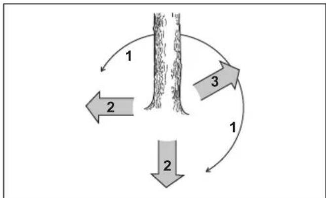
- Do a check of the area for obstacles such as stones, branches and holes. You must have a clear path of retreat when the tree starts to fall. Your path of retreat must be approximately 135 degrees away from the felling direction.
- The danger zone
- The path of retreat
- The felling direction
flowchart
graph TD
    A["1"] --> B["2"]
    B --> C["3"]
    C --> A
    style A fill:#f9f,stroke:#333
    style B fill:#bbf,stroke:#333
    style C fill:#bfb,stroke:#333
To fell a tree
Husqvarna recommends you to make the directional cuts and then use the safe corner method when you fell a tree. The safe corner method helps you to make a correct felling hinge and control the felling direction.

WARNING: Do not fell trees with a diameter that is more than two times larger than the guide bar length. For this, you must have special training.
The felling hinge
The most important procedure during tree felling is to make the correct felling hinge. With a correct felling hinge, you control the felling direction and make sure that the felling procedure is safe.
The thickness of the felling hinge must be equal and a minimum of 10% of the tree diameter.

WARNING: If the felling hinge is incorrect or too thin, you have no control of the felling direction.

natural_image
Diagram of concentric circular layers with a vertical bar and directional arrows, no text or symbols presentTo make the directional cuts
- Make the directional cuts 14 of the diameter of the tree. Make a 45^-70^ angle between the top directional cut and bottom directional cut.

a) Make the top directional cut. Align the felling direction mark (1) of the product with the felling direction of the tree (2). Stay behind the product and keep the tree on your left side. Cut with a pull stroke. b) Make the bottom directional cut. Make sure that the end of the bottom directional cut is at the same point as the end of the top directional cut.

- Make sure that the bottom directional cut is horizontal and at a 90^ angle to the felling direction.
To use the safe corner method
The felling cut must be made slightly above the directional cut.

natural_image
Diagram showing a tree trunk with a horizontal line and an arrow indicating direction, no text or symbols present.
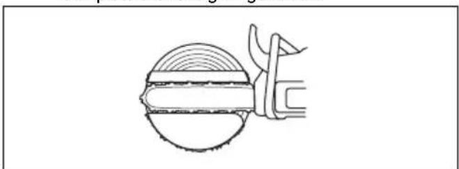
WARNING: Be careful when you cut with the guide bar tip. Start to cut with the lower section of the guide bar tip as you make a bore cut into the trunk.

natural_image
Simple line drawing of a mechanical tool or tool with no text, numbers, or symbols- If the usable cutting length is longer than the tree diameter, do these steps (a-d).
a) Make a bore cut straight into the trunk to complete the felling hinge width.
natural_image
Simple line drawing of a mechanical component or tool with no text or symbolsb) Cut on the pull stroke until 13 of the trunk is left.
c) Pull the guide bar 5-10 cm/2-4 in rearward.
d) Cut through the remaining of the trunk to complete a safe corner that is 5-10 cm/2-4 in wide.

natural_image
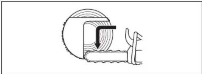
Cross-sectional diagram of a mechanical component with internal layered structure and directional arrow (no text or labels)- If the usable cutting length is shorter than the tree diameter, do these steps (a-d).
a) Make a bore cut straight into the trunk. The bore cut must extend 3/5 of the tree diameter.
b) Cut on the pull stroke through the remaining trunk.
natural_image
Cross-sectional diagram of a mechanical or electrical component with layered structure and internal components (no text or symbols)c) Cut straight into the trunk from the other side of the tree to complete the felling hinge.
d) Cut on the push stroke, until 13 of the trunk is left, to complete the safe corner.

natural_image
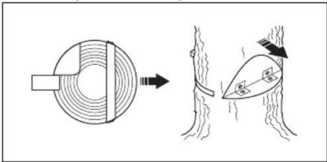
Technical line drawing of a mechanical component with concentric grooves and a central shaft (no text or symbols)- Put a wedge in the kerf straight from behind.
natural_image
Diagram illustrating a mechanical or structural change between two components, showing a circular component and a triangular structure with a hanging part (no text or symbols present)- Cut off the corner to make the tree fall.
Note: If the tree does not fall, hit the wedge until it does.
- When the tree starts to fall, use the path of retreat to move away from the tree. Move a minimum of 5 m/15 ft away from the tree.
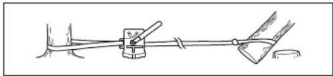
To free a trapped tree

WARNING: It is very dangerous to remove a trapped tree and there is a high accident risk. Keep out of the risk zone and do not try to fell a trapped tree.

The safest procedure is to use one of the following winches:
- Tractor-mounted

natural_image
Simple line drawing of a tractor pulling a tree with a lever, no text or symbols present- Portable
natural_image
Simple line drawing of a mechanical clamp or lever system with no text or symbolsTo cut trees and branches that are in tension
- Figure out which side of the tree or branch that is in tension.
- Figure out where the point of maximum tension is.

natural_image
Simple line drawing of a ball rolling down an uneven stream with a downward arrow indicating flow (no text or symbols)- Examine which is the safest procedure to release the tension.
Note: In some situations the only safe procedure is to use a winch and not your product.
- Keep a position where the tree or branch can not hit you when the tension is released.

natural_image
Diagram of a mechanical or structural system with two curved surfaces, directional arrows, and a central vertical component (no text or symbols)- Make one or more cuts of sufficient depth necessary to decrease the tension. Cut at or near the point of maximum tension. Make the tree or branch break at the point of maximum tension.

natural_image
Cross-sectional diagram of a geological or structural cross-section showing layered rock formations and terrain (no text or labels)
WARNING: Do not cut straight through a tree or branch that is in tension.

WARNING: Be very careful when you cut a tree that is in tension. There is a risk that the tree moves quickly before or after you cut it. Serious injury can occur if you are in an incorrect position or if you cut incorrectly.
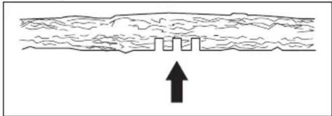
- If you must cut across tree/branch, make 2 to 3 cuts, 1 in. apart and with a depth of 2 in.
natural_image
Diagram showing a cross-section of a layered structure with an upward arrow indicating direction (no text or symbols present)- Continue to cut more into the tree until the tree/branch bends and the tension is released.

natural_image
Diagram showing airflow or particle movement between two curved surfaces with arrows indicating direction (no text or symbols)- Cut the tree/branch from the opposite side of the bend, after the tension is released.
To use the product in cold weather

CAUTION: Snow and cold weather can cause operation problems. Risk of too low engine temperature or ice on the air filter and the carburetor.
- If the temperature is 0^ C/32°F or colder, carefully remove the plug in the cylinder cover.

natural_image
Technical line drawing of a car interior showing internal components and a circular component (no text or symbols)- If the temperature is -5^ / 23^ or colder, assemble the winter cover on the starter housing.

natural_image
Technical line drawing of a chain-linking device with attached bracket (no text or symbols)
CAUTION: Remove the winter cover if the temperature increases above -5^/23^ . Assemble the plug in the cylinder cover if the temperature increases above 0^/32^ . Risk of too high engine temperature and damage to the engine.
Maintenance
Introduction

WARNING: Read and understand the safety chapter before you do maintenance on the product.
Maintenance schedule
| Daily maintenance Weekly maintenance Monthly maintenance | ||
| Clean the external parts of the product and make sure that there is no oil on the handles. | Clean the cooling system. Refer to To clean the cooling system on page 33. | Do a check of the brake band. Refer to To do a check of the brake band on page 22. |
| Do a check of the throttle trigger and throttle trigger lockout. Refer to To do a check of the throttle trigger and throttle trigger lockout on page 23. | Do a check of the starter, starter rope and return spring. | Do a check of the clutch centre, clutch drum and clutch spring. |
| Make sure that there is no damage on the vibration damping units. | Lubricate the needle bearing. Refer to To lubricate the needle bearing on page 31. | Clean the spark plug. Refer to To do a check of the spark plug on page 27. |
| Clean and do a check of the chain brake. Refer to To do a check of the chain brake on page 23To do a check of the front hand guard and the chain brake activation on page 22. | Remove burrs from the edges of the guide bar. Refer to To do a check of the guide bar on page 32. | Clean the external parts of the carburettor. |
| Do a check of the chain catcher. Refer to To do a check of the chain catcher on page 23. | Clean or replace the spark arrestor mesh on the muffler. | Do a check of the fuel filter and the fuel hose. Replace if necessary. |
| Turn the guide bar, do a check of the lubrication hole and clean the groove in the guide bar. Refer to To do a check of the guide bar on page 32. | Clean the carburetor area. Do a check of all cables and connections. | |
| Make sure that the guide bar and saw chain are getting sufficient oil. | Clean or replace the air filter. Refer to To clean the air filter on page 26. | Empty the fuel tank. |
| Do a check of the saw chain. Refer to To examine the cutting equipment on page 32. | Clean between the cylinder fins. Empty the oil tank. | |
| Sharpen the saw chain and do a check of its tension. Refer to To sharpen the saw chain on page 27. | ||
| Do a check of the chain drive sprocket. Refer to To do a check of the spur sprocket on page 31. | ||
| Clean the air intake on the starter. | ||
| Make sure that nuts and screws are tightened. | ||
| Do a check of the stop switch. Refer to To do a check of the start/stop switch on page 24. | ||
| Make sure that these are no fuel leaks from the engine, tank or fuel lines. | ||
| Make sure that the saw chain does not rotate when the engine is at idle speed. | ||
| Make sure that there is no damage on the right hand guard. | ||
| Make sure that the muffler is correctly attached, has no damages and that no parts of the muffler are missing. | ||
Maintenance and checks of the safety devices on the product
To do a check of the brake band
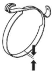
- Use a brush to remove wood dust, resin and dirt from the chain brake and clutch drum. Dirt and wear can decrease the function of the brake.
natural_image
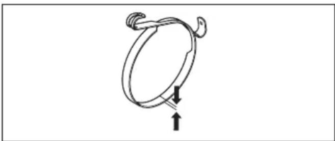
Simple line drawing of a rope or rope loop with directional arrows indicating movement (no text or symbols)- Do a check of the brake band. The brake band must be at a minimum of 0.6 mm/0.024 in thick at its thinnest point.
To do a check of the front hand guard and the chain brake activation
- Make sure that the front hand guard is not damaged and that there are no defects, such as cracks.
natural_image
Simple line drawing of a rope or rope loop with an upward arrow indicating direction (no text or symbols)- Make sure that the front hand guard moves freely and that it is attached safely to the clutch cover.
natural_image
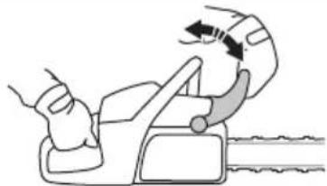
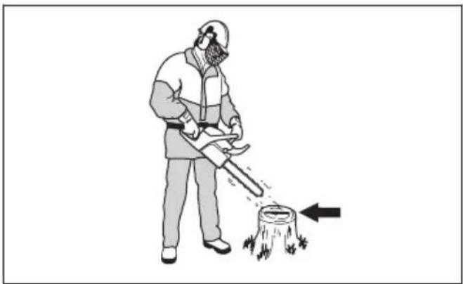
Illustration of a hand using a car seatbelt to lift a seatbelt, showing the wheel and seat (no text or symbols)- Hold the product with 2 hands above a stump or other stable surface.

WARNING: The engine must be off.
- Let go of the front handle and let the guide bar tip fall against the stump.

natural_image
Illustration of a person using a power saw to cut tree bark (no text or symbols)
natural_image
Illustration of a person using a power manual to cut tree bark (no text or symbols)- Make sure that the chain brake engages as the guide bar tip hits the stump.
To do a check of the chain brake
- Start the product. Refer to To start the product on page 12 for instructions.

WARNING: Make sure that the saw chain does not touch the ground or other objects.
- Hold the product tightly.
- Apply full throttle and tilt your left wrist against the front hand guard to engage the chain brake. The saw chain must stop immediately.



WARNING: Do not let go of the front handle.
To do a check of the throttle trigger and throttle trigger lockout
- Make sure that the throttle trigger and throttle trigger lockout move freely and that the return spring works correctly.

natural_image
Line drawing of a chain-linking device with arrows indicating motion direction (no text or symbols)- Press down the throttle trigger lockout and make sure that it goes back to its initial position when you release it.

natural_image
Line drawing of a mechanical clamp or clip device with directional arrows indicating movement (no text or symbols)- Make sure that the throttle trigger is locked at the idle position when the throttle trigger lockout is released.

natural_image
Line drawing of a chain-linking device with a black arrow indicating motion direction (no text or symbols)- Start the product and apply full throttle.
- Release the throttle trigger and make sure that the saw chain stops and stays stationary.

WARNING: If the saw chain rotates when the throttle trigger is in the idle position, speak to your servicing dealer.
To do a check of the chain catcher
- Make sure that there is no damage on the chain catcher.
- Make sure that the chain catcher is stable and attached to the body of the product.

natural_image
Diagram showing a chain-linker tool interacting with a car's side panel, with an arrow indicating the process (no text or symbols present)To do a check of the right hand guard
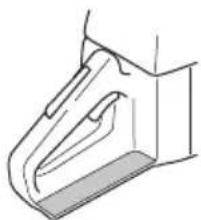
• Make sure that the right hand guard is not damaged and that there are no defects, such as cracks.
natural_image
Technical line drawing of a mechanical component or bracket (no text or symbols)To do a check of the vibration damping system
- Make sure that there are no cracks or deformation on the vibration damping units.
- Make sure that the vibration damping units are correctly attached to the engine unit and handle unit.
Refer to Product overview on page 2 for information about where the vibration damping system is on your product.
To do a check of the start/stop switch
- Start the engine.
- Press the start/stop switch down to the STOP position. The engine must stop.

To do a check of the muffler

WARNING: Do not use a product that has a defective muffler or a muffler that is in bad condition.

WARNING: Do not use a product if the spark arrestor mesh on the muffler is missing or defective.
-
Examine the muffler for damages and defects.
-
Make sure that the muffler is correctly attached to the product.

natural_image
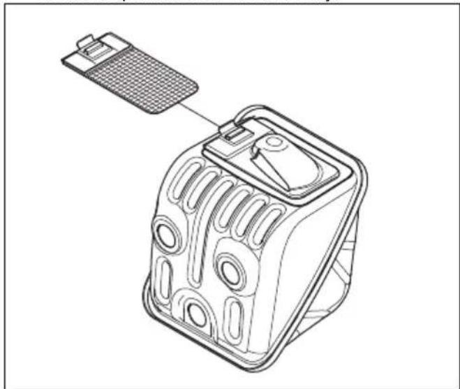
Technical line drawing of a mechanical component with a tool inserted, no visible text or symbols- If your product has a special spark arrestor mesh, clean the spark arrestor mesh weekly.
natural_image
Line drawing of a mechanical device with a handle and internal components (no text or symbols)- Replace a damaged spark arrestor mesh.

CAUTION: If the spark arrestor mesh is blocked the product becomes too hot and this causes damage to the cylinder and piston.
Carburetor adjustment
Because of environmental and emissions laws, your product has adjustment limitations on the carburetor adjuster screws. This decreases the harmful exhaust
fumes from your product. You can only turn the adjustment screws maximum 12 turn.

Basic adjustments and run-in
The basic carburetor adjustments are done at the factory. For the recommended idle speed, refer to Technical data on page 35.

CAUTION: Do not operate the product at too high speed during the first 10 hours of operation.

CAUTION: If the saw chain rotates at idle speed, turn the idle speed screw counterclockwise until the saw chain stops.
To adjust the low speed needle (L)
- Turn the low speed needle clockwise until stop.
Note: If the product has a bad acceleration capacity or if the idle speed is not correct, turn the low speed needle counterclockwise. Turn the low speed needle until the acceleration capacity and idle speed is correct.
To adjust the idle speed screw (T)
- Start the product.
- Turn the idle speed screw clockwise until the saw chain starts to rotate.
- Turn the idle speed screw counterclockwise until the saw chain stops.
Note: The idle speed is correctly adjusted when the engine runs correctly in all positions. The idle speed must also be safely below the speed at which the saw chain starts to rotate.

WARNING: If the saw chain does not stop when you turn the idle speed screw, speak to your servicing dealer. Do not use the product until it is correctly adjusted.
To adjust the high speed needle (H)
The engine is adjusted at the factory to operate at sea level. At higher altitudes, in different weather or different temperatures it can be necessary to adjust the high speed needle.
- Turn the high speed needle to make adjustments.

CAUTION: Do not turn the high speed needle screw across the adjustment limitation stop. This can cause damage to the piston and the cylinder.
To examine if the carburetor is correctly adjusted
• Make sure that the product has the correct acceleration capacity.
• Make sure that the product 4-cycles a little at full throttle.
- Make sure that the saw chain does not rotate at idle speed.
- If the product is not easy to start or has less acceleration capacity, adjust the low and high speed needles.

CAUTION: Incorrect adjustments can cause damage to the engine.
To replace a broken or worn starter rope
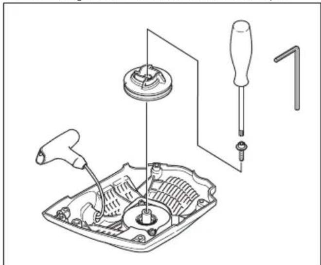
- Loosen the screws to the starter housing
- Remove the starter housing.

natural_image
Line drawing of a chainsaw with arrows indicating force or movement (no text or symbols)-
Pull out the starter rope approximately 30 cm/12 in and put it in the notch on the pulley.
-
Let the pulley rotate slowly rearward to release the recoil spring.

natural_image
Two-step automotive assembly diagram showing tool application on engine components (no text or labels)- Remove the center screw and the pulley.

WARNING: You must be careful when you replace the return spring or the starter rope. The recoil spring is in tension when it is wound up in the starter housing. If you are not careful, it can eject and cause injuries. Use protective glasses and protective gloves.
-
Remove the used starter rope from the handle and the pulley.
-
Attach a new starter rope to the pulley. Wind the starter rope approximately 3 turns around the pulley.
-
Connect the pulley to the recoil spring. The end of the recoil spring must engage in the pulley.
-
Assemble the pulley and center screw.
-
Pull the starter rope through the hole in the starter housing and the starter rope handle.
-
Make a tight knot at the end of the starter rope.
natural_image
Technical line drawing of a mechanical assembly with tool, screwdriver, and housing (no text or symbols)To tighten the recoil spring
-
Put the starter rope into the notch in the pulley.
-
Turn the starter pulley approximately 2 turns clockwise.
-
Pull the starter rope handle and pull out the starter rope fully.
- Put your thumb on the pulley.
- Move your thumb and release the starter rope.
- Make sure that you can turn the pulley 12 turn after the starter rope is fully extended.

natural_image
Illustration of hands assembling a mechanical component with a circular arrow indicating rotation (no text or symbols)To assemble the starter housing on the product
- Pull out the starter rope and put the starter in position against the crankcase.
- Slowly release the starter rope until the pulley engages with the pawls.
- Tighten the screws that hold the starter.

natural_image
Line drawing of a hand using a tool to cut a saw (no text or symbols)To clean the air filter
Clean the air filter regularly from dirt and dust. This prevents carburetor malfunctions, starting problems, loss of engine power, wear to engine parts and more fuel consumption than usual.
- Remove the cylinder cover and the air filter.
- Use a brush or shake the air filter clean. Use detergent and water to clean it fully.
Note: An air filter that is used for a long time can not be fully cleaned. Replace the air filter regularly and always replace a defective air filter.
- Attach the air filter and make sure that the air filter seals tightly against the filter holder.

natural_image
Technical line drawing of a mechanical device showing internal components and a close-up view of the housing (no text or symbols)Note: Because of different work conditions, weather or season, your product can be used with different types of air filter. Speak to your servicing dealer for more information.
To do a check of the spark plug

CAUTION: Use the recommended spark plug. Refer to Technical data on page 35. An incorrect spark plug can cause damage to the product.
- If the product is not easy to start or to operate or if the product operates incorrectly at idle speed, examine the spark plug for unwanted materials. To decrease the risk of unwanted material on the spark plug electrodes, do these steps:
a) make sure that the idle speed is correctly adjusted.
b) make sure that the fuel mixture is correct.
c) make sure that the air filter is clean.
- Clean the spark plug if it is dirty.
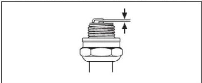
- Make sure that the electrode gap is 0.5 mm/0.020 in.
natural_image
Technical line drawing of a mechanical component with no visible text or symbols- Replace the spark plug monthly or more frequently if necessary.
To sharpen the saw chain
Information about the guide bar and saw chain

WARNING: Use protective gloves when you use or do maintenance on the saw chain. A saw chain that does not move can also cause injuries.
Replace a worn or damaged guide bar or saw chain with the guide bar and saw chain combination recommended by Husqvarna. This is necessary to keep the safety functions of the product. Refer to Accessories on page 36, for a list of replacement bar and chain combinations that we recommend.
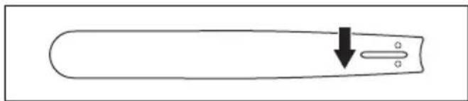
- Guide bar length, in/cm. Information about the guide bar length can usually be found on the rear end of the guide bar.
natural_image
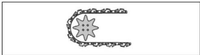
Simple line drawing of a pen-like object with a downward arrow and two circular holes (no text or symbols)• Number of teeth on bar tip sprocket (T).
natural_image
Simple line drawing of a chain with a star-shaped object inside, no text or symbols present.- Chain pitch, in. The distance between the drive links of the saw chain must align with the distance of the teeth on the bar tip sprocket and drive sprocket.

• Number of drive links. The number of drive links is decided by the type of guide bar.

natural_image
Pure mechanical linkage diagram without any text, numbers, or symbols- Bar groove width, in/mm. The groove width in guide bar must be the same as the chain drive links width.
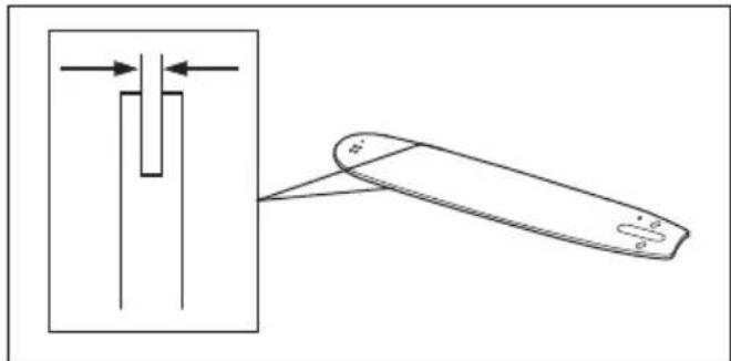
natural_image
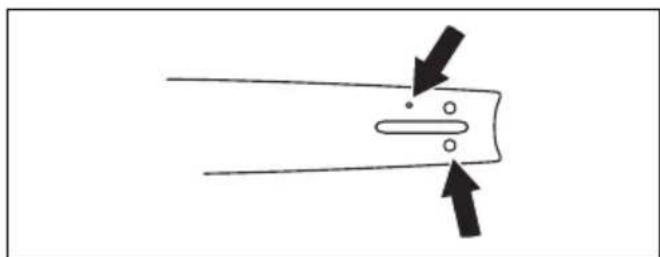
Diagram showing a mechanical component with arrows indicating direction, alongside a simplified view of its tip (no text or symbols)- Chain oil hole and hole for chain tensioner. The guide bar must align with product.
natural_image
Simple line drawing of a mechanical component with two arrows indicating direction (no text or symbols)- Drive link width, mm/in.

natural_image
Technical line drawing of a mechanical component with a vertical scale and directional arrow (no text or symbols)General information about how to sharpen the cutters
Do not use a blunt saw chain. If the saw chain is blunt, you must apply more pressure to push the guide bar through the wood. If the saw chain is very blunt, there will be no wood chips but sawdust.
A sharp saw chain eats through the wood and the wood chips becomes long and thick.
The cutting tooth (A) and the depth gauge (B) together makes the cutting part of the saw chain, the cutter. The difference in height between the two gives the cutting depth (depth gauge setting).

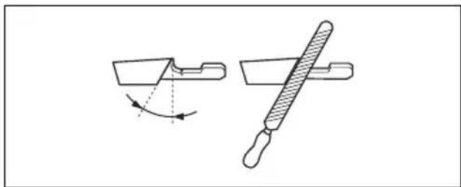
When you sharpen the cutter, think about the following:
- Filing angle.
natural_image
Technical line drawing of a mechanical tool with an arrow indicating rotation and a cross-sectional view (no text or symbols)- Cutting angle.

natural_image
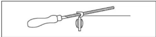
Simple line drawing of a mechanical component with curved arrows indicating motion or force (no text or symbols)- File position.
natural_image
Line drawing of a screwdriver holding a lever and pivot (no text or symbols)- Round file diameter.

natural_image
Simple line drawing of a dropper with a small symbol (no text or labels)It is not easy to sharpen a saw chain correctly without the correct equipment. Use Husqvarna file gauge. This will help you to keep maximum cutting performance and the kickback risk at a minimum.

WARNING: The force of the kickback increases a lot if you do not follow the sharpening instructions.
Note: Refer to To sharpen the saw chain on page 27 for information about sharpening of the saw chain.
To sharpen the cutters
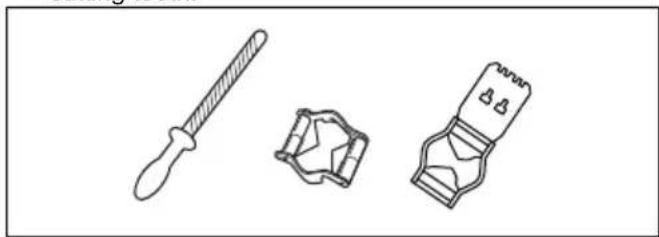
- Use a round file and a file gauge to sharpen the cutting teeth.
natural_image
Line drawings of three mechanical components: a dropper, a bracket, and a clip (no text or symbols)Note: Refer to Accessories on page 36 for information about which file and gauge that Husqvarna recommends for your saw chain.
- Apply the file gauge correctly on to the cutter. Refer to the instruction supplied with the file gauge.
- Move the file from the inner side of the cutting teeth and out. Decrease the pressure on the pull stroke.

natural_image
Mechanical assembly diagram showing a clamp or bracket with diagonal bracing and mounting holes (no text or symbols)- Remove material from one side of all the cutting teeth.
- Turn the product around and remove material on the other side.
- Make sure that all cutting teeth are the same length.
General information about how to adjust the depth gauge setting
The depth gauge setting (C) decreases when you sharpen the cutting tooth (A). To keep maximum cutting performance you must remove filing material from the depth gauge (B) to receive the recommended depth gauge setting. See Accessories on page 36 for instructions about how to receive the correct depth gauge setting for your saw chain.


WARNING: The risk of kickback increases if the depth gauge setting is too large!
To adjust the depth gauge setting
Before you adjust the depth gauge setting or sharpen the cutters, refer to General information about how to sharpen the cutters on page 28, for instructions. We
recommend you to adjust the depth gauge setting after each third operation that you sharpen the cutting teeth.
We recommend that you use our depth gauge tool to receive the correct depth gauge setting and bevel for the depth gauge.

natural_image
Illustration of two mechanical tools: a radial tool and a textured device (no text or symbols)- Use a flat file and a depth gauge tool to adjust the depth gauge setting. Only use Husqvarna depth gauge tool to get the correct depth gauge setting and bevel for the depth gauge.
- Put the depth gauge tool on the saw chain.
Note: See the package of the depth gauge tool for more information about how to use the tool.
- Use the flat file to remove the part of the depth gauge that extends through the depth gauge tool.

natural_image
Technical line drawing of a mechanical component with no visible text or symbolsTo adjust the tension of the saw chain (455 Rancher, 460 Rancher)

WARNING: A saw chain with an incorrect tension can come loose from the guide bar and cause serious injury or death.
A saw chain becomes longer when you use it. Adjust the saw chain regularly.
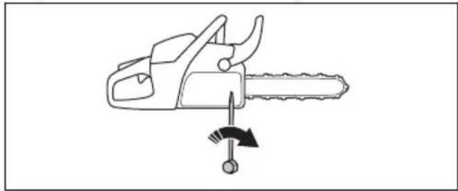
- Loosen the bar nuts that hold the clutch cover/chain brake. Use a wrench.

natural_image
Line drawing of a chain saw with a directional arrow indicating motion (no text or symbols)Note: Some models have only one bar nut.
- Tighten the bar nuts by hand as tightly as you can.
-
Lift the front of the guide bar and turn the chain tensioning screw. Use a wrench.
-
Tighten the saw chain until it is tight against the guide bar but still can move easily.
natural_image
Line drawing of a chainsaw with a hammer and gear, showing a press or adjustment mechanism (no text or symbols)-
Tighten the bar nuts using the wrench and lift the front of the guide bar at the same time.
-
Make sure you can pull the saw chain around freely by hand and that it does not hang from the guide bar.

natural_image
Illustration of two hands performing a rope or cable manipulation technique (no text or symbols present)Note: Refer to Product overview on page 2 for the position of the chain tensioning screw on your product.
To adjust the tension of the saw chain (455e Rancher)

WARNING: A saw chain with an incorrect tension can come loose from the guide bar and cause serious injury or death.
A saw chain becomes longer when you use it. Adjust the saw chain regularly.
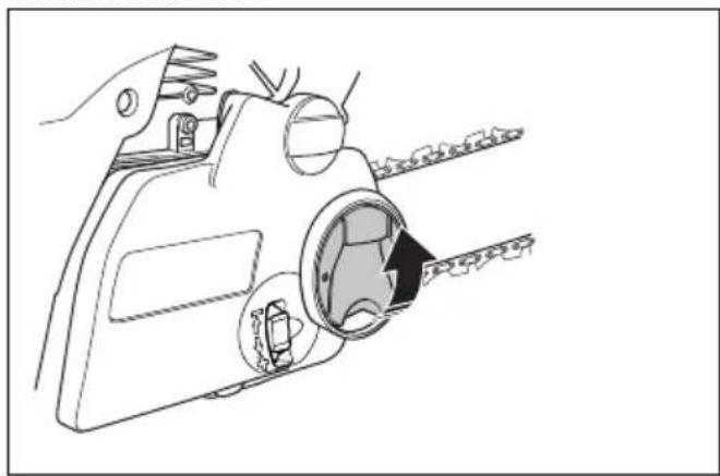
- Release the knob.
natural_image
Line drawing of a hand holding a camera with lens and gear assembly (no text or symbols)- Turn the knob counterclockwise to loosen the clutch cover.

natural_image
Diagram of a hand operating a mechanical device with a tool and circular arrow indicating rotation (no text or symbols)- Turn the chain tensioning wheel down (+) to increase the tension of the saw chain. Turn the chain tensioning wheel up (-) to decrease the tension of the saw chain.

natural_image
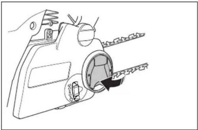
Technical line drawing of a mechanical device with a close-up inset showing internal components (no text or symbols)- Turn the knob clockwise to tighten the clutch cover.

natural_image
Diagram of a mechanical device with a gear and rotating arrow, showing no text or symbols- Fold the knob down.
natural_image
Line drawing of a hand holding a mechanical device with a circular component inserted, showing internal components (no text or symbols)- Make sure you can pull the saw chain around freely by hand and that it does not hang from the guide bar.

natural_image
Illustration of two hands holding a curved object with directional arrows indicating motion or force (no text or symbols)To do a check of the saw chain lubrication
- Start the product and let it operate at 34 throttle. Hold the bar approximately 20 cm/8 in above a surface of light color.
- If the saw chain lubrication is correct, you see a clear line of oil on the surface after 1 minute.
natural_image
Illustration of a person using a manual power tool to cut tree bark (no text or symbols present)- If the saw chain lubrication does not operate correctly, do a check of the guide bar. Refer to To do a check of the guide bar on page 32 for instructions. Speak to your servicing dealer if the maintenance steps does not help.
To do a check of the spur sprocket
The clutch drum has a spur sprocket that is welded on the clutch drum.

natural_image
Technical line drawing of a mechanical gear assembly (no text or symbols)- Regularly do a visual check of the degree of wear on the spur sprocket. Replace the clutch drum with the spur sprocket if there is too much wear.
To lubricate the needle bearing
- Pull the front hand guard rearward to disengage the chain brake.
- Loosen the bar nuts and remove the clutch cover.
Note: Some models have only one bar nut.
- Put the product on a stable surface with the clutch drum up.
- Apply engine oil to the clutch drum. Let the clutch drum rotate. Use engine oil or a bearing grease of high quality.

natural_image
Technical diagram of a mechanical assembly with a tool inserted into a circular housing, showing internal components and arrows indicating motion (no text or symbols present)To examine the cutting equipment
- Make sure that there are no cracks in rivets and links and that no rivets are loose. Replace if it is necessary.

natural_image
Diagram showing mechanical assembly with two views of a chain (no text or symbols present)- Make sure that the saw chain is easy to bend. Replace the saw chain if it is rigid.
- Compare the saw chain with a new saw chain to examine if the rivets and links are worn.
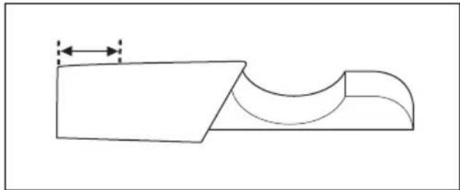
- Replace the saw chain when the longest part of the cutting tooth is less than 4 mm/0.16 in. Also replace the saw chain if there are cracks on the cutters.
natural_image
Pure technical line drawing of a mechanical part with no text or symbolsTo do a check of the guide bar
- Make sure that the oil channel is not blocked. Clean if it is necessary.

natural_image
Simple line drawing of a switch handle with a black arrow pointing to the button (no text or symbols)- Examine if there are burrs on the edges of the guide bar. Remove the burrs using a file.

natural_image
Diagram showing a tool interacting with a mechanical part, with no visible text or symbols- Clean the groove in the guide bar.

natural_image
Line drawing of a hand holding a cylindrical object, no text or symbols present- Examine the groove in the guide bar for wear. Replace the guide bar if it is necessary.

- Examine if the guide bar tip is rough or very worn.

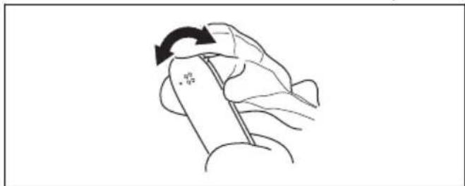
- Make sure that the bar tip sprocket turns freely and that the lubricating hole in the bar tip sprocket is not blocked. Clean and lubricate if it is necessary.
natural_image
Line drawing of a hand holding a pen with an arrow indicating rotation (no text or symbols)- Turn the guide bar daily to extend its life cycle.

natural_image
Simple line drawing of a tool handle with an arrow indicating direction (no text or symbols)To do maintenance on the fuel tank and the chain oil tank
- Drain and clean the fuel tank and the chain oil tank regularly.
- Replace the fuel filter yearly or more frequently if necessary.

CAUTION: Contamination in the tanks causes malfunction.
To adjust the chain oil flow

WARNING: Stop the engine before you make adjustments to the oil pump.
- Turn the adjustment screw for the oil pump. Use a screwdriver or combination wrench.
a) Turn the adjustment screw clockwise to decrease the chain oil flow.
b) Turn the adjustment screw counterclockwise to increase the chain oil flow.

natural_image
Technical line drawing of a mechanical device with directional arrows indicating motion or force (no text or symbols)Recommended settings for the oil pump
• Guide bar length 13-15 in/33-38 cm: Position 1
• Guide bar length 16-18 in/40-46 cm: Position 2
• Guide bar length 20-24 in/51-61 cm: Position 3
Air cleaning system
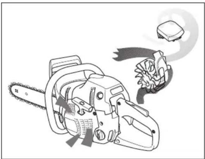
AirInjection ^™ is a centrifugal air cleaning system that removes dust and dirt before the particles are caught by the air filter. AirInjection ^™ extends the life of the air filter and the engine.
natural_image
Illustration of a chain-linking tool with gear and a warning symbol (no text or labels)To clean the cooling system
The cooling system keeps the engine temperature down. The cooling system includes the air intake on the starter (A) and the air guide plate (B), the pawls on the flywheel (C), the cooling fins on the cylinder (D) and the cylinder cover (E).
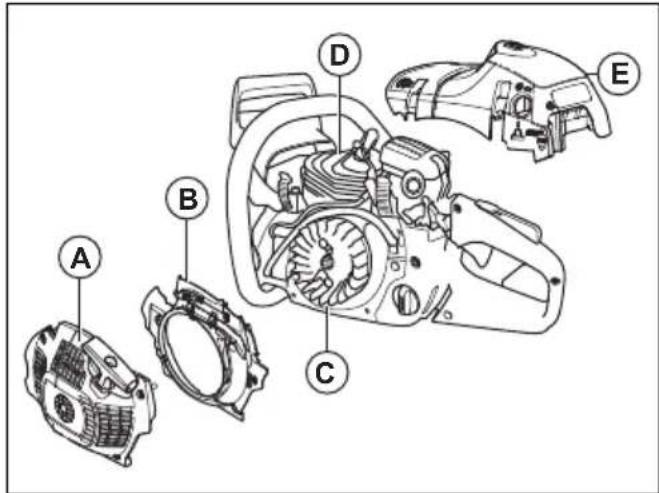
- Clean the cooling system with a brush weekly or more frequently if it is necessary.
- Make sure that the cooling system is not dirty or blocked.

CAUTION: A dirty or blocked cooling system can make the product too hot, which can cause damage to the product.
Troubleshooting
The engine does not start
| Product part to examine Possible cause | Action | |
| Starter pawls The starter pawls are blocked. Adjust or replace the starter pawls. | ||
| Clean around the pawls. | ||
| Speak to an approved service workshop. | ||
| Fuel tank Incorrect fuel type. Drain the fuel tank and fill with cor- | rect fuel. | |
| The fuel tank is filled with chain oil. If you have tried to start the product, speak to your servicing dealer. If you have not tried to start the product, drain the fuel tank. | ||
| Ignition, no spark The spark plug is dirty or wet. Make sure that the spark plug is dry and clean. | ||
| The electrode gap is incorrect. Clean the spark plug. Make sure that the electrode gap and spark plug is correct, and that the correct spark plug type is the recommended or equivalent. | ||
| Refer to Technical data on page 35 for the correct electrode gap. | ||
| Spark plug and cylinder The spark plug is loose. Tighten the spark plug. | ||
| Engine is flooded because of repeated starts with full choke after ignition. | ||
| Remove and clean the spark plug. Put the product on its side with the spark plug hole away from you. Pull the starter rope handle 6-8 times. Assemble the spark plug and start the product. Refer to To start the product on page 12. | ||
The engine starts but stops again
| Product part to examine | Possible cause Action | |
| Fuel tank Incorrect fuel type. Drain the | fuel tank and fill with cor- | rect fuel. |
| Carburetor The idle speed is not correct. | Speak to your servicing dealer. | |
| Air filter Clogged air filter. Clean or replace the air filter. | ||
| Fuel filter Clogged fuel filter. | Replace the fuel filter. |
Transportation and storage
Transportation and storage
- For storage and transportation of the product and fuel, make sure that there are no leaks or fumes. Sparks or open flames, for example from electrical devices or boilers, can start a fire.
• Always use approved containers for storage and transportation of fuel. - Empty the fuel and chain oil tanks before transportation or before long-term storage. Discard the fuel and chain oil at an applicable disposal location.
- Use the transportation guard on the product to prevent injuries or damage to the product. A saw chain that does not move can also cause serious injuries.
- Remove the spark plug cap from the spark plug and engage the chain brake.
- Attach the product safely during transportation.
To prepare your product for long-term storage
- Disassemble and clean the saw chain and the groove in the guide bar.

CAUTION: If the saw chain and guide bar are not cleaned, they can become rigid or blocked.
- Attach the transportation guard.
- Clean the product. Refer to Maintenance on page 21 for instructions.
- Do a complete servicing of the product.
Technical data
Technical data
| Husqvarna 455 Rancher Husqvarna 455e Rancher Husqvarna 460 Rancher | |||
| Engine | |||
| Cylinder displacement, cm^3 | 55.5 55.5 60.3 | ||
| Idle speed, rpm 2700-2900 2700-2900 2700-2900 2700-2900 2700-2900 2700-2900 2700-2900 2700-2900 2700-2900 2700-2900 2700-2901 | |||
| Maximum engine power acc. to ISO 8893, kW/hp @ rpm | 2.6/3.5 @ 9000 2.6/3.5 @ 9000 2.7/3.6 @ 9000 | ||
| Ignition system ^1 | |||
| Spark plug NGK BPMR 7A/ChampionRCJ 7Y | NGK BPMR 7A/ ChampionRCJ 7Y | NGK BPMR 7A/ ChampionRCJ 7Y | |
| Electrode gap, mm 0.5 0.5 0.5 0.5 | |||
| Fuel and lubrication system | |||
| Fuel tank capacity, liter/ cm^3 | 0.44/440 0.44/440 0.44/440 | ||
| Oil tank capacity, liter/ cm^3 | 0.32/320 0.32/320 0.32/320 | ||
| Type of oil pump Automatic Automatic Automatic | |||
| Weight | |||
| Weight, kg 6.0 6.0 6.0 | |||
| Noise emissions2 | |||
| Sound power level, measured dB(A) | 112 112 112 | ||
| Sound power level, guaranteed LWA dB(A) | 114 114 114 | ||
| Sound levels3 | |||
| Equivalent sound pressure level at the operator's ear, dB(A) | 104 104 104 | ||
| Equivalent vibration levels, ahveq4 | |||
| Front handle, m/s2 | 3.8 3.8 3.8 | ||
| Rear handle, m/s2 | 6.9 6.9 6.9 | ||
| Saw chain/guide bar | |||
| Type of drive sprocket/number of teeth | Spur/7 Spur/7 Spur/7 | ||
| Saw chain speed at 133% of maximum engine power speed, m/s. | 26.6 26.6 26.6 | ||
Accessories
Recommended cutting equipment
Chainsaw models Husqvarna 455 Rancher, 455e Rancher, 460 Rancher have been evaluated for safety according to EN ISO 11681-1:2011 (Machinery for forestry - Portable chainsaw safety requirements and testing) and fulfill the safety requirements when equipped with the below listed guide bar and saw chain combinations.
Low kickback saw chain
A saw chain that is designated as Low kickback saw chain, meets the low kickback requirement specified in ANSI B175.1-2012.
Kickback and guide bar nose radius
For sprocket nose bars the nose radius is specified by the number of teeth, such as 10T. For solid guide bars the nose radius is specified by the dimension of the nose radius. For a given guide bar length, you can use a guide bar with smaller nose radius than given.
| Guide bar Saw chain | ||||||
| Length, in/cm | Pitch, in Gauge, | in/mm | Max. nose ra- dius | Type Length, drive links (no.) | Low kickback | |
| 15/38 3/8 0.058 | 1.5 11T Husqvarna | H42 | 56 | |||
| 16/41 60 | ||||||
| 18/46 68 | ||||||
| 20/50 72 | ||||||
| 24/61 84 | ||||||
| 15/38 3/8 0.058 | 1.5 11T Husqvarna | C85 | 56 | |||
| 16/41 60 | ||||||
| 18/46 68 | ||||||
| 20/50 72 | ||||||
| 24/61 84 | ||||||
| 13/33 0.325 0.0 | 50/1.3 10T Husqvarna | H30 | 56 Yes | |||
| 15/38 64 | ||||||
| 16/41 66 | ||||||
| 18/46 72 | ||||||
| 20/50 80 | ||||||
| 13/33 0.325 0.0 | 58/1.5 10T Husqvarna | H25 | 56 Yes | |||
| 15/38 64 | ||||||
| 16/41 66 | ||||||
| 18/46 72 | ||||||
| 20/50 12T 80 | ||||||
The usable cutting length is usually 1 in less than the nominal guide bar length.
Pixel
Pixel is a guide bar and saw chain combination that is more light weight and designated to offer more energy efficient use by cutting narrow cuts. Both guide bar and saw chain need to be Pixel to get these benefits. Pixel cutting equipment is marked with this symbol.

Filing equipment and filing angles
Use a Husqvarna file gauge to sharpen the saw chain. A Husqvarna file gauge makes sure that you get the correct filing angles. The part numbers are given in the table below.
If you are not sure how to identify the type of saw chain on your product, refer to www.husqvarna.com for more information.
| [1x40] | 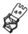 |  | 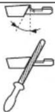 |  | |
| H30 4.8 mm | / 3/16 in 505 69 81 | -08 | 0.025 in / 0.65 mm | 30° 80° | |
| H25 4.8 mm | / 3/16 in 505 69 81 | -09 | 0.025 in / 0.65 mm | 30° 80° | |
| H42 5.5 mm | / 7/32 in 505 24 35 | -01 | 0.025 in / 0.65 mm | 25° 55° | |
| C85 5.5 mm | / 7/32 in 586 93 85 | -01 | 0.025 in / 0.65 mm | 30° 60° |
EC Declaration of Conformity
EC Declaration of conformity
Husqvarna AB, SE-561 82 Huskvarna, Sweden, tel: +46-36-146500, declares under sole responsibility that the chainsaws for forest service Husqvarna 455 Rancher, 455e Rancher, 460 Rancher from 2016's serial numbers and onwards (the year is clearly stated in plain text on the type plate with subsequent serial number), are in conformity with the requirements of the COUNCIL'S DIRECTIVES:
• of May 17, 2006 "relating to machinery" 2006/42/EC.
- of February 26, 2014 "relating to electromagnetic compatibility" 2014/30/EU.
- of May 8, 2000 "relating to the noise emissions in the environment" 2000/14/EC.
- of June 8, 2011 "on the restriction of the use of certain hazardous substances in electrical and electronic equipment" 2011/65/EU.
The following standards have been applied: EN ISO 12100:2010, EN ISO 14982:2009, EN ISO 11681-1:2011, EN 50581:2012.
Notified body: 0404, RISE SMP Svensk Maskinprovning AB, Box 7035, SE-750 07 Uppsala, Sweden, has carried out EC type examination in accordance with the machinery directive's (2006/42/EC) article 12, point 3b. The certificates for EC type examination in accordance with annex IX, have the numbers: 0404/09/2081 – 455 Rancher, 455e Rancher, 0404/09/2082 - 460 Rancher.
In addition, 0404, RISE SMP Svensk Maskinprovning AB, Box 7035, SE-750 07 Uppsala, Sweden, has certified conformity with annex V of the Council's Directive of May 8, 2000 "relating to the noise emissions in the environment" 2000/14/EC. The certificates have the numbers: 01/161/054, 01/161/084.
For information relating to noise emissions, refer to Technical data on page 35.
The supplied chainsaw conforms to the example that underwent EC type examination.
Huskvarna, 20160330
Per Gustafsson, Development manager (authorized representative for Husqvarna AB and responsible for technical documentation.)
Husqvarna®
www.husqvarna.com
Original instructions


- Introduction
- Intended use
- Product description
- Product overview
- Symbols on the product
- EU V
- Safety
- Safety definitions
- General safety instructions
- Safety instructions for operation
- Personal protective equipment
- Safety devices on the product
- Chain brake and front hand guard
- Throttle trigger lockout
- Chain catcher
- Right hand guard
- Vibration damping system
- Start/stop switch
- Muffler
- Fuel safety
- Safety instructions for maintenance
- Safety instructions for the cutting equipment
- Assembly
- To assemble the guide bar and saw chain (455 Rancher, 460 Rancher)
- To assemble the guide bar and saw chain (455e Rancher)
- Operation
- To do a function check before you use the product
- Fuel
- Premixed fuel
- To mix fuel
- Gasoline
- Two-stroke oil
- To fill the fuel tank
- To do a run-in
- To use the correct chain oil
- Kickback information
- Common questions about kickback
- To start the product
- To prepare to start with a cold engine
- To prepare to start with a warm engine
- To stop the product
- Pull stroke and push stroke
- To use the cutting technique
- To cut a trunk on the ground
- To cut a trunk that has support on one end
- To cut a trunk that has support on two ends
- To use the limbing technique
- To use the tree felling technique
- To keep a safe distance
- To calculate the felling direction
- To clear the trunk and prepare your path of retreat
- To fell a tree
- The felling hinge
- To make the directional cuts
- To use the safe corner method
- To free a trapped tree
- To cut trees and branches that are in tension
- To use the product in cold weather
- Maintenance
- Maintenance schedule
- Maintenance and checks of the safety devices on the product
- To do a check of the brake band
- To do a check of the front hand guard and the chain brake activation
- To do a check of the chain brake
- To do a check of the throttle trigger and throttle trigger lockout
- To do a check of the chain catcher
- To do a check of the right hand guard
- To do a check of the vibration damping system
- To do a check of the start/stop switch
- To do a check of the muffler
- Carburetor adjustment
- Basic adjustments and run-in
- To adjust the low speed needle (L)
- To adjust the idle speed screw (T)
- To adjust the high speed needle (H)
- To examine if the carburetor is correctly adjusted
- To replace a broken or worn starter rope
- To tighten the recoil spring
- To assemble the starter housing on the product
- To clean the air filter
- To do a check of the spark plug
- To sharpen the saw chain
- Information about the guide bar and saw chain
- General information about how to sharpen the cutters
- To sharpen the cutters
- General information about how to adjust the depth gauge setting
- To adjust the depth gauge setting
- To adjust the tension of the saw chain (455 Rancher, 460 Rancher)
- To adjust the tension of the saw chain (455e Rancher)
- To do a check of the saw chain lubrication
- To do a check of the spur sprocket
- To lubricate the needle bearing
- To examine the cutting equipment
- To do a check of the guide bar
- To do maintenance on the fuel tank and the chain oil tank
- To adjust the chain oil flow
- Recommended settings for the oil pump
- Air cleaning system
- To clean the cooling system
- Troubleshooting
- Transportation and storage
- To prepare your product for long-term storage
- Technical data
- Accessories
- Recommended cutting equipment
- Low kickback saw chain
- Kickback and guide bar nose radius
- Pixel
- Filing equipment and filing angles
- EC Declaration of Conformity
- Husqvarna®
Brand : HUSQVARNA
Model : 460 R
Category : Saw